Author Topic: #562 – Electroboom!  (Read 108340 times)

0 Members and 2 Guests are viewing this topic.

Offline jesuscf

  • Frequent Contributor
  • **
  • Posts: 499
  • Country: ca
Re: #562 – Electroboom!
« Reply #600 on: December 02, 2021, 06:42:11 pm »
The video is correct.  He even calculates the correct and unique voltage between VAD (VJX at 33:38, something Lewin was unable to do), followed with an explanation of what happens if use  KVL without including the induced EMF (what Lewin did).  So, what is your point exactly?

Well, it's a Nothing Burger, how our host would be calling it. While you can calculate a voltage for Vad, it is more mathturbation than anything else.

It is not trivial to compute for other than artificial setups with simple paths, perfect symmetry or at least uniformity of the electric field, and actually observing it is also quite complicated, because all measurements would again be taken along paths through a non-conservative electric field, which adds another dimension of error.

So, you'd compute a value for Vad, making various assumptions about the fields involved, then calculate a path based on the same assumptions, then try to make your measurements and calculations match in reality. But at no point you would be sure if any of it is correct. Plus there are geometries where it is not possible to measure it.

The same guy has a good video on the merits of PD to "salvage KVL" on his channel. It is quite thorough IMHO, though a bit long winded, but still worth watching in detail.

https://youtu.be/I1kYKF2x9Ns

Although the video you linked is correct, I think it goes in to too much detail and sometimes it is hard to decipher what he tries to explain.   In my opinion this video from Bob Duhamel from RSD Academy explains it better:


Homer: Kids, there's three ways to do things; the right way, the wrong way and the Max Power way!
Bart: Isn't that the wrong way?
Homer: Yeah, but faster!
 

Offline bsfeechannelTopic starter

  • Super Contributor
  • ***
  • Posts: 1667
  • Country: 00
Re: #562 – Electroboom!
« Reply #601 on: December 02, 2021, 07:40:23 pm »


PS: "Team KVL", don't get your hopes up too early ;)

The video is correct.  He even calculates the correct and unique voltage between VAD (VJX at 33:38, something Lewin was unable to do), followed with an explanation of what happens if use  KVL without including the induced EMF (what Lewin did).  So, what is your point exactly?

The point is this:


What he calculated was the scalar potential difference between those two points and he points out [pun unintended] how difficult or even impossible would be to measure it. The voltages measured by the voltmeters in his calculations match exactly what Lewin predicted and then he, Mehdi, and many others measured: two different voltages.

So, if you're saying the video is correct, this means that you are recognizing that Lewin is absolutely right and Mehdi is dead wrong. Congratulations.


The following users thanked this post: HuronKing

Offline bsfeechannelTopic starter

  • Super Contributor
  • ***
  • Posts: 1667
  • Country: 00
Re: #562 – Electroboom!
« Reply #602 on: December 02, 2021, 08:19:12 pm »
Although the video you linked is correct, I think it goes in to too much detail and sometimes it is hard to decipher what he tries to explain.   In my opinion this video from Bob Duhamel from RSD Academy explains it better:


Yeah. The video thinkfat posted is absolutely correct, thank you very much. What is not correct is the video by this RSD Academy guy. Stay away from him. He doesn't understand electromagnetism, preaches pseudoscience, and wants your money for his Patreon account.

The quackery of his explanation is evident when @3:41 he said the meter will measure zero volts. To justify this he tries to explain how a piece of static wire under the effect of an electric field produced by a varying magnetic field is going to generate voltages inside it. He forgot that the charges accumulated at the ends of the wire will generate an electric field that's is going to be in the opposite direction and equal intensity to the induced field and the resultant will be zero.

For this guy the Coulumb force is like the gravitational field for Wile E. Coyote: it only works when it is amusing.


The following users thanked this post: Sredni, HuronKing

Offline jesuscf

  • Frequent Contributor
  • **
  • Posts: 499
  • Country: ca
Re: #562 – Electroboom!
« Reply #603 on: December 02, 2021, 08:33:17 pm »


PS: "Team KVL", don't get your hopes up too early ;)

The video is correct.  He even calculates the correct and unique voltage between VAD (VJX at 33:38, something Lewin was unable to do), followed with an explanation of what happens if use  KVL without including the induced EMF (what Lewin did).  So, what is your point exactly?

The point is this:


What he calculated was the scalar potential difference between those two points and he points out [pun unintended] how difficult or even impossible would be to measure it. The voltages measured by the voltmeters in his calculations match exactly what Lewin predicted and then he, Mehdi, and many others measured: two different voltages.

So, if you're saying the video is correct, this means that you are recognizing that Lewin is absolutely right and Mehdi is dead wrong. Congratulations.

Just carry on watching a bit longer, and try to understand what he is saying!
Homer: Kids, there's three ways to do things; the right way, the wrong way and the Max Power way!
Bart: Isn't that the wrong way?
Homer: Yeah, but faster!
 

Offline Sredni

  • Frequent Contributor
  • **
  • Posts: 686
  • Country: aq
Re: #562 – Electroboom!
« Reply #604 on: December 02, 2021, 09:09:58 pm »


PS: "Team KVL", don't get your hopes up too early ;)

The video is correct.  He even calculates the correct and unique voltage between VAD (VJX at 33:38, something Lewin was unable to do), followed with an explanation of what happens if use  KVL without including the induced EMF (what Lewin did).  So, what is your point exactly?

The point is this:


What he calculated was the scalar potential difference between those two points and he points out [pun unintended] how difficult or even impossible would be to measure it. The voltages measured by the voltmeters in his calculations match exactly what Lewin predicted and then he, Mehdi, and many others measured: two different voltages.

So, if you're saying the video is correct, this means that you are recognizing that Lewin is absolutely right and Mehdi is dead wrong. Congratulations.

Just carry on watching a bit longer, and try to understand what he is saying!

Dude, that's Trevor Kearney. If Jesse hadn't flown away to another galaxy to avoid answering my question on the circuit path for Lewin's ring, he would tell you Trevor is "Armchair Physics Nobel Prize" number one. He's probably one of the most active people on YouTube trying to debunk Mehdi and the other KVLers.  :palm:
All instruments lie. Usually on the bench.
 
The following users thanked this post: HuronKing

Offline bsfeechannelTopic starter

  • Super Contributor
  • ***
  • Posts: 1667
  • Country: 00
Re: #562 – Electroboom!
« Reply #605 on: December 02, 2021, 09:35:48 pm »
I just wanted to point this out because in this particular case I know that I am measuring voltage V1 across a 0 ohm wire, but my instrument is showing some other voltage than zero violating the Ohm's law, which is a clear indication that there is something wrong in my probing, and the measurement setup is picking up interference from some magnetic field affecting my measurement.

What I am saying is that

1. That voltage is NOT interference: it's exactly what that piece of system is supposed to do (hence your probing is correct: you put a voltmeter across the secondary of a transformer and the 12V you measure are not 'interference', despite the fact that if you follow the magnet wires inside the device all you see is... wire)
2. Ohm's law is obeyed (if you use the correct physics, of course)

This is what I came up with when thinking about this circuit and when KVL holds and doesn't hold.

In figure a) the circuit is inside a magnetic field, the voltage between points A and D depends on path, it is not possible to create a lumped model for the source creating the 1mA current, and KVL doesn't hold.

In figure b) the circuit is only partially inside a magnetic field creating a transformer with a single-turn secondary, thus it is possible to create a lumped model for the source creating the 1mA current like in figure c, and KVL holds.

Figure c is a lumped model for figure b with a (voltage) source creating the 1mA current when the magnetic field is increasing, and KVL holds.


Is my reasoning correct?

Edit: Added some clarifications.

Absolutely correct.
 

Offline jesuscf

  • Frequent Contributor
  • **
  • Posts: 499
  • Country: ca
Re: #562 – Electroboom!
« Reply #606 on: December 02, 2021, 09:52:24 pm »


PS: "Team KVL", don't get your hopes up too early ;)

The video is correct.  He even calculates the correct and unique voltage between VAD (VJX at 33:38, something Lewin was unable to do), followed with an explanation of what happens if use  KVL without including the induced EMF (what Lewin did).  So, what is your point exactly?

The point is this:


What he calculated was the scalar potential difference between those two points and he points out [pun unintended] how difficult or even impossible would be to measure it. The voltages measured by the voltmeters in his calculations match exactly what Lewin predicted and then he, Mehdi, and many others measured: two different voltages.

So, if you're saying the video is correct, this means that you are recognizing that Lewin is absolutely right and Mehdi is dead wrong. Congratulations.

Just carry on watching a bit longer, and try to understand what he is saying!

Dude, that's Trevor Kearney. If Jesse hadn't flown away to another galaxy to avoid answering my question on the circuit path for Lewin's ring, he would tell you Trevor is "Armchair Physics Nobel Prize" number one. He's probably one of the most active people on YouTube trying to debunk Mehdi and the other KVLers.  :palm:

That guy got the correct value for VAD.  Did you get the correct value for VAD yet?
Homer: Kids, there's three ways to do things; the right way, the wrong way and the Max Power way!
Bart: Isn't that the wrong way?
Homer: Yeah, but faster!
 

Offline bsfeechannelTopic starter

  • Super Contributor
  • ***
  • Posts: 1667
  • Country: 00
Re: #562 – Electroboom!
« Reply #607 on: December 02, 2021, 11:49:12 pm »
Dude, that's Trevor Kearney. If Jesse hadn't flown away to another galaxy to avoid answering my question on the circuit path for Lewin's ring, he would tell you Trevor is "Armchair Physics Nobel Prize" number one. He's probably one of the most active people on YouTube trying to debunk Mehdi and the other KVLers.  :palm:

Isn't it hilarious that KVLers be so obtuse that they can't even recognize when a video was made to debunk their claims, due to their absolute lack of understanding of what is being discussed?

Congratulations, Mehdi Sadaghdar! Look what you've done! You've spawned a whole bunch of brain-damaged mock engineers like yourself.
 
The following users thanked this post: HuronKing

Offline jesuscf

  • Frequent Contributor
  • **
  • Posts: 499
  • Country: ca
Re: #562 – Electroboom!
« Reply #608 on: December 02, 2021, 11:54:38 pm »
Dude, that's Trevor Kearney. If Jesse hadn't flown away to another galaxy to avoid answering my question on the circuit path for Lewin's ring, he would tell you Trevor is "Armchair Physics Nobel Prize" number one. He's probably one of the most active people on YouTube trying to debunk Mehdi and the other KVLers.  :palm:

Isn't it hilarious that KVLers be so obtuse that they can't even recognize when a video was made to debunk their claims, due to their absolute lack of understanding of what is being discussed?

Congratulations, Mehdi Sadaghdar! Look what you've done! You've spawned a whole bunch of brain-damaged mock engineers like yourself.

You didn't watch the video, or if you did, you didn't understand it, which will not surprise me!
Homer: Kids, there's three ways to do things; the right way, the wrong way and the Max Power way!
Bart: Isn't that the wrong way?
Homer: Yeah, but faster!
 

Offline Sredni

  • Frequent Contributor
  • **
  • Posts: 686
  • Country: aq
Re: #562 – Electroboom!
« Reply #609 on: December 03, 2021, 01:38:18 am »
In figure a) the circuit is inside a magnetic field, the voltage between points A and D depends on path, it is not possible to create a lumped model for the source creating the 1mA current, and KVL doesn't hold.

In figure b) the circuit is only partially inside a magnetic field creating a transformer with a single-turn secondary, thus it is possible to create a lumped model for the source creating the 1mA current like in figure c, and KVL holds.

Figure c is a lumped model for figure b with a (voltage) source creating the 1mA current when the magnetic field is increasing, and KVL holds.

Is my reasoning correct?

Yes. There is only one fine point that require some annotations.
Technically the lumped circuit model requires for the circuit to be shrunk (or to be 'shrinkable') to a point. It's a way to make sure that the circuit path itself does not participate in any phenomena that is related to geometry. The variable flux 'exploited' by magnetic components requires a finite area - you cannot shrink your circuit to a point if it has to contain a finite area; likewise, charge separation and accumulation that is exploited by electrostatic devices requires... space. So, if your circuit path can be thought as an elastic band that can be shrunk to a point, you are guaranteed you exclude these effects from the 'inside' of your circuit - they can only be 'provided' by the components.

This is why when dealing with lumped circuits, the lumped components are sometimes shown to offer their terminals close together. All the pairs of points on the circuit path corresponding to every lumped component do not interfere with the shrinking of the circuit path. In reality, if you have a component that doesn't offer terminals side by side you can choose: extend the component's terminals or extend the circuit as I have shown in a post a few pages prior. This leaves some leverage to argue about the lumpiness of either the component or the circuit. Considering components with terminals separated by a very small gap avoids this controversy entirely.

Then, of course the symbol of a battery for the lumped component signifies that you are considering a specific instant in time (the linearly increasing flux is a didactic tool). I too, prefer to use battery to represent the contribute of the inductive EMF, but sometimes it is better to remind it.
« Last Edit: December 03, 2021, 01:43:38 am by Sredni »
All instruments lie. Usually on the bench.
 
The following users thanked this post: bsfeechannel, HuronKing

Offline Kalvin

  • Super Contributor
  • ***
  • Posts: 2145
  • Country: fi
  • Embedded SW/HW.
Re: #562 – Electroboom!
« Reply #610 on: December 03, 2021, 12:53:16 pm »
Here is the circuit from Lewin's video with 1V voltage source.

If the KVL holds, it possible to split the original circuit in half at D and A by inserting two antiparallel 1mA current sources between nodes D and A. After split, the currents and the voltages of the original circuit remain unchanged.

If the KVL holds, it possible to split the original circuit in half at D and A by inserting a voltage source between nodes D and A with value V(D,A) because there is no current flowing through the new voltage source. After split, the currents and the voltages of the original circuit remain unchanged.

It can be seen that KVL holds and it is possible to spilt the circuit in half at D and A.

The 1V voltage source can be located some other point in the original circuit, which will affect the equivalent circuit values, but KVL will still hold.


Here is the circuit from Lewin's video when the solenoid is generating 1mA current flowing in the circuit. It can be seen that KVL fails when the circuit contains of non-conservative fields, and thus it is not possible to split the circuit at D and A.

« Last Edit: December 03, 2021, 01:32:15 pm by Kalvin »
 

Offline Kalvin

  • Super Contributor
  • ***
  • Posts: 2145
  • Country: fi
  • Embedded SW/HW.
Re: #562 – Electroboom!
« Reply #611 on: December 03, 2021, 01:10:53 pm »
The simple circuit analysis above suggests that Dr. Lewin had it right, and there were no probing errors involved, even if the results look counterintuitive. KVL fails when there are non-conservative fields present.
 
The following users thanked this post: HuronKing

Offline jesuscf

  • Frequent Contributor
  • **
  • Posts: 499
  • Country: ca
Re: #562 – Electroboom!
« Reply #612 on: December 03, 2021, 03:07:21 pm »
Here is the circuit from Lewin's video with 1V voltage source.

If the KVL holds, it possible to split the original circuit in half at D and A by inserting two antiparallel 1mA current sources between nodes D and A. After split, the currents and the voltages of the original circuit remain unchanged.

If the KVL holds, it possible to split the original circuit in half at D and A by inserting a voltage source between nodes D and A with value V(D,A) because there is no current flowing through the new voltage source. After split, the currents and the voltages of the original circuit remain unchanged.

It can be seen that KVL holds and it is possible to spilt the circuit in half at D and A.

The 1V voltage source can be located some other point in the original circuit, which will affect the equivalent circuit values, but KVL will still hold.


Here is the circuit from Lewin's video when the solenoid is generating 1mA current flowing in the circuit. It can be seen that KVL fails when the circuit contains of non-conservative fields, and thus it is not possible to split the circuit at D and A.


I see, you too, are confused with the 'non-conservative fields' statement.  Although it may appear that in the circuit the electric field is non-conservative because it is changing over time, so it is the magnetic field.   What happens is that the the total energy in the circuit is conservative: all energy added to the circuit is consumed by the circuit.  From the circuital point of view is easier to work with instantaneous power than energy.  For example at time t when the EMF is 1V the calculated current is 1mA, then: EMF*I=I2(R1+R2).  The external varying magnetic field is adding 1mW to the circuit and the circuit is consuming 1mW.  The fields in the circuit are conservative.
Homer: Kids, there's three ways to do things; the right way, the wrong way and the Max Power way!
Bart: Isn't that the wrong way?
Homer: Yeah, but faster!
 

Offline thinkfat

  • Supporter
  • ****
  • Posts: 2150
  • Country: de
  • This is just a hobby I spend too much time on.
    • Matthias' Hackerstübchen
Re: #562 – Electroboom!
« Reply #613 on: December 03, 2021, 03:51:15 pm »
I see, you too, are confused with the 'non-conservative fields' statement.  Although it may appear that in the circuit the electric field is non-conservative because it is changing over time, so it is the magnetic field.   What happens is that the the total energy in the circuit is conservative: all energy added to the circuit is consumed by the circuit.  From the circuital point of view is easier to work with instantaneous power than energy.  For example at time t when the EMF is 1V the calculated current is 1mA, then: EMF*I=I2(R1+R2).  The external varying magnetic field is adding 1mW to the circuit and the circuit is consuming 1mW.  The fields in the circuit are conservative.
Emphasis mine.

The "fields in the circuit" are not to be confused with the fields outside of the circuit. The "non-conservative electric field" described by the Maxwell-Faraday equation is not in the circuit.

PS: "change over time" is not a sign of non-conservativeness. The "curl" is.
« Last Edit: December 03, 2021, 03:57:02 pm by thinkfat »
Everybody likes gadgets. Until they try to make them.
 

Offline bsfeechannelTopic starter

  • Super Contributor
  • ***
  • Posts: 1667
  • Country: 00
Re: #562 – Electroboom!
« Reply #614 on: December 03, 2021, 05:31:13 pm »
I see, you too, are confused with the 'non-conservative fields' statement.  Although it may appear that in the circuit the electric field is non-conservative because it is changing over time, so it is the magnetic field.   What happens is that the the total energy in the circuit is conservative: all energy added to the circuit is consumed by the circuit.  From the circuital point of view is easier to work with instantaneous power than energy.  For example at time t when the EMF is 1V the calculated current is 1mA, then: EMF*I=I2(R1+R2).  The external varying magnetic field is adding 1mW to the circuit and the circuit is consuming 1mW.  The fields in the circuit are conservative.

He understands what a non conservative field is. You don't. That's why you think he's confused.
 

Offline jesuscf

  • Frequent Contributor
  • **
  • Posts: 499
  • Country: ca
Re: #562 – Electroboom!
« Reply #615 on: December 03, 2021, 07:20:32 pm »
I see, you too, are confused with the 'non-conservative fields' statement.  Although it may appear that in the circuit the electric field is non-conservative because it is changing over time, so it is the magnetic field.   What happens is that the the total energy in the circuit is conservative: all energy added to the circuit is consumed by the circuit.  From the circuital point of view is easier to work with instantaneous power than energy.  For example at time t when the EMF is 1V the calculated current is 1mA, then: EMF*I=I2(R1+R2).  The external varying magnetic field is adding 1mW to the circuit and the circuit is consuming 1mW.  The fields in the circuit are conservative.

He understands what a non conservative field is. You don't. That's why you think he's confused.

As usual, the one very confused is you, because is not 'field' (singular) but instead 'fields' (plural).
Homer: Kids, there's three ways to do things; the right way, the wrong way and the Max Power way!
Bart: Isn't that the wrong way?
Homer: Yeah, but faster!
 

Offline jesuscf

  • Frequent Contributor
  • **
  • Posts: 499
  • Country: ca
Re: #562 – Electroboom!
« Reply #616 on: December 03, 2021, 07:45:39 pm »
Here is the circuit from Lewin's video with 1V voltage source.

If the KVL holds, it possible to split the original circuit in half at D and A by inserting two antiparallel 1mA current sources between nodes D and A. After split, the currents and the voltages of the original circuit remain unchanged.

If the KVL holds, it possible to split the original circuit in half at D and A by inserting a voltage source between nodes D and A with value V(D,A) because there is no current flowing through the new voltage source. After split, the currents and the voltages of the original circuit remain unchanged.

It can be seen that KVL holds and it is possible to spilt the circuit in half at D and A.

The 1V voltage source can be located some other point in the original circuit, which will affect the equivalent circuit values, but KVL will still hold.


Here is the circuit from Lewin's video when the solenoid is generating 1mA current flowing in the circuit. It can be seen that KVL fails when the circuit contains of non-conservative fields, and thus it is not possible to split the circuit at D and A.


By the way, your equivalent circuit for the loop with the two resistors is incorrect.  If you use the correct  equivalent circuit:


You will see that KVL holds even if you split the circuit as in the second set of your images.
Homer: Kids, there's three ways to do things; the right way, the wrong way and the Max Power way!
Bart: Isn't that the wrong way?
Homer: Yeah, but faster!
 

Offline Kalvin

  • Super Contributor
  • ***
  • Posts: 2145
  • Country: fi
  • Embedded SW/HW.
Re: #562 – Electroboom!
« Reply #617 on: December 03, 2021, 08:17:54 pm »
Here is the circuit from Lewin's video with 1V voltage source.

If the KVL holds, it possible to split the original circuit in half at D and A by inserting two antiparallel 1mA current sources between nodes D and A. After split, the currents and the voltages of the original circuit remain unchanged.

If the KVL holds, it possible to split the original circuit in half at D and A by inserting a voltage source between nodes D and A with value V(D,A) because there is no current flowing through the new voltage source. After split, the currents and the voltages of the original circuit remain unchanged.

It can be seen that KVL holds and it is possible to spilt the circuit in half at D and A.

The 1V voltage source can be located some other point in the original circuit, which will affect the equivalent circuit values, but KVL will still hold.


Here is the circuit from Lewin's video when the solenoid is generating 1mA current flowing in the circuit. It can be seen that KVL fails when the circuit contains of non-conservative fields, and thus it is not possible to split the circuit at D and A.


By the way, your equivalent circuit for the loop with the two resistors is incorrect.  If you use the correct  equivalent circuit:


You will see that KVL holds even if you split the circuit as in the second set of your images.

Please note that the original distributed circuit model in figure a below is not equivalent with the lumped circuit models in figures b and c. Your suggestion is identical with the lumped model in figure c with the voltage source split in half. However, your circuit is not identical with the original circuit any more, because you are transforming a non-conservative circuit into a conservative circuit by introducing those voltage sources. Thus I would say that your suggestion is not a valid transformation.


Offline jesuscf

  • Frequent Contributor
  • **
  • Posts: 499
  • Country: ca
Re: #562 – Electroboom!
« Reply #618 on: December 03, 2021, 11:13:43 pm »
Here is the circuit from Lewin's video with 1V voltage source.

If the KVL holds, it possible to split the original circuit in half at D and A by inserting two antiparallel 1mA current sources between nodes D and A. After split, the currents and the voltages of the original circuit remain unchanged.

If the KVL holds, it possible to split the original circuit in half at D and A by inserting a voltage source between nodes D and A with value V(D,A) because there is no current flowing through the new voltage source. After split, the currents and the voltages of the original circuit remain unchanged.

It can be seen that KVL holds and it is possible to spilt the circuit in half at D and A.

The 1V voltage source can be located some other point in the original circuit, which will affect the equivalent circuit values, but KVL will still hold.


Here is the circuit from Lewin's video when the solenoid is generating 1mA current flowing in the circuit. It can be seen that KVL fails when the circuit contains of non-conservative fields, and thus it is not possible to split the circuit at D and A.


By the way, your equivalent circuit for the loop with the two resistors is incorrect.  If you use the correct  equivalent circuit:


You will see that KVL holds even if you split the circuit as in the second set of your images.

Please note that the original distributed circuit model in figure a below is not equivalent with the lumped circuit models in figures b and c. Your suggestion is identical with the lumped model in figure c with the voltage source split in half. However, your circuit is not identical with the original circuit any more, because you are transforming a non-conservative circuit into a conservative circuit by introducing those voltage sources. Thus I would say that your suggestion is not a valid transformation.


Check the attached pdf from Electromagnetics by Notaros, pages 279-280, example 6.6.
Homer: Kids, there's three ways to do things; the right way, the wrong way and the Max Power way!
Bart: Isn't that the wrong way?
Homer: Yeah, but faster!
 

Offline Jesse Gordon

  • Regular Contributor
  • *
  • Posts: 126
  • Country: us
Re: #562 – Electroboom!
« Reply #619 on: December 04, 2021, 06:52:27 am »
Dude, that's Trevor Kearney. If Jesse hadn't flown away to another galaxy to avoid answering my question on the circuit path for Lewin's ring, he would tell you Trevor is "Armchair Physics Nobel Prize" number one. He's probably one of the most active people on YouTube trying to debunk Mehdi and the other KVLers.  :palm:

I didn't fly away, I told you I unequivocally proved that Team Lewin absoutely refused to answer basic questions - EVERY SINGLE (then active) MEMBER of Team Lewin absolutely refused to answer my question. What's else to discuss when Team Lewin denies observable reality?

As I said, I need to limit my time here to a couple times a week because I get paid by the hour to do other work (Self employed) and things reached a stage where it was clear that Team Lewin is holding to their beliefs even if it means denying observable reality.

As you've seen from my youtube channel comments, Trevor Kearney is a very nice gent - but you will also see that he does not have as good a grasp of the topic as he thinks.
He too refused to answer numerous questions which I asked him, and also made false predictions about reality - in fact, when I told him that KVL would hold with a loop made from two transformer secondary windings and two resistors, he didn't believe me, so that's why I made the "KVL Holds with an iron core" video.

He too refused to answer my simple question that you all refused to answer - If it measures like it's working, why is it not working? is it a technicality?

There seem to be two kinds of people - those who live and breath reality and deal with math as needed, and those who live in the virtual world of math and deal with reality when needed.

Or in your case, deny observable reality.
 

Offline Jesse Gordon

  • Regular Contributor
  • *
  • Posts: 126
  • Country: us
Re: #562 – Electroboom!
« Reply #620 on: December 04, 2021, 07:01:12 am »
I would be a little concerned with my probing if I measured V1 something else than 0V across a 0 ohm wire [when |V2 + V3| > 0].


Don't forget that not all voltage differences are ohmic.

There's batteries, capacitors, solar cells, peltier junctions, and yes, the ever popular inductive transformer.

All of those things can have voltages across them which would appear to violate ohms law if we assume that all voltage differences are strictly ohmic.

not all voltage differences are purely ohmic.

And one of those that is not strictly ohmic is the winding of a transformer.
 

Offline Jesse Gordon

  • Regular Contributor
  • *
  • Posts: 126
  • Country: us
Re: #562 – Electroboom!
« Reply #621 on: December 04, 2021, 07:29:45 am »
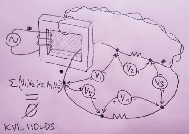
Question: In the following diagram, in a real life physical lab test performed with real (time synchronized) volt meters with a real transformer and real resistors CONNECTED AS SHOWN, will the readings of all the volt meters sum to zero, within the accuracy and resolution limitations of the volt meters? YES or NO.

(Or if you believe SOMETIMES is the answer, then explain one scenario for a YES condition and one scenario for a NO condition WITH THE VOLT METERS CONNECTED AS SHOWN - Running additional conductors through the transformer core is not allowed - nor is removing existing conductors from through the transformer core!)


You do realize that this is not a circuit that is equivalent to the "Lewin Ring", or equivalent to the circuit I gave you to solve, right?

Of course! "That" is a simple circuit that can be easily constructed and measured by anybody.

I was hoping we could find some common ground there and at least agree that KVL appears -- and perhaps does - hold on the above topology.

But like all the others, you are afraid to answer either because you don't have what it takes to test reality, or you know that your answer will undermine your belief.


Quote
That was my challenge to you, the task was to find the voltages across the resistors and the wires:


And that's what you came up with:


Which of course brings up the question why you found it necessary to add a "transformer secondary" to find the voltage across "2R".

You call it an "added secondary" but it MEASURES AND MODELS the exact same as if the right hand volt meter was instead on the left. Doesn't matter where it is. It doesn't loop through the core, which means it's not another winding.

Remember, KVL requires two-terminal elements. If we're not using a two-terminal element, OF COURSE kvl isn't even applicable.

You want me to run a volt meter lead through the core which effectively adds another secondary winding, making it into a 3 terminal element, and as such, it's no longer applicable for KVL.

By having only ONE PATH through the core, we effectively have what MODELS AND MEASURES as a black box 2 terminal element, which is what KVL requires - and we can unambiguously measure the voltage across THOSE TWO TERMINALS and KVL holds.

Remember, a toroidal transformer MODELS AND MEASURES as if the entire induced voltage takes place at the plane through the center of the core.

How and where it is actually induced is irrelevant to KVL so long as an unambiguous voltage measurement can be physically obtained. By modeling the core as being a mythical fluxgate or stargate or whatever you guys called it, then we get a physical unambiguous voltage measurement and KVL holds.

So how about it? A yes or no on the top picture question in this comment?

Dude, you know the answer is yes, KVL will measure to hold. We should be past this. This is an easy one!

Talking about the open ended air core transformer and it's half turns would be much more interesting!
 

Offline Sredni

  • Frequent Contributor
  • **
  • Posts: 686
  • Country: aq
Re: #562 – Electroboom!
« Reply #622 on: December 04, 2021, 07:30:26 am »
I didn't fly away,
Oh, good. So you can answer my question, since I have answered yours.

Quote
I told you I unequivocally proved that Team Lewin absoutely refused to answer basic questions - EVERY SINGLE (then active) MEMBER of Team Lewin absolutely refused to answer my question. What's else to discuss when Team Lewin denies observable reality?

Maybe we did answer the question, and you are not able to accept the answer so you keep asking it over and over hoping to receive the answer you want?

Quote
He too refused to answer numerous questions which I asked him, and also made false predictions about reality - in fact, when I told him that KVL would hold with a loop made from two transformer secondary windings and two resistors, he didn't believe me, so that's why I made the "KVL Holds with an iron core" video.

He too refused to answer my simple question that you all refused to answer - If it measures like it's working, why is it not working? is it a technicality?

As I repeated about a dozen times, if a circuit is lumpABLE and you choose the circuit path in such a way that it does not include a variable magnetic field, then you can consider all voltages between any two points on that circuit path as if they were path independent. The circuit can be considered lumpED and KVL works.

IF the circuit is lumpABLE.

There are in our universe, circuits that are not lumpable: I call them UNlumpable circuits.
They are circuits where you cannot find a circuit path that does not encloses the variable flux region.
Lewin's ring IS such a circuit because it REQUIRES the two resistors to be on the opposite sides of a variable magnetic flux region.
You think Lewin's ring is lumpABLE?

Well, PROVE IT.

This is Lewin's ring: two resistors in a single loop that goes around a circular region (let's consider it of the same size as the loop, so you can see there is no 'room to twist' the wires) of variable magnetic field. The resistors are required to be on the opposite sides of the variable magnetic field region.


link https://i.postimg.cc/pLmfyHxZ/Lewin-ring-is-unlumpable.jpg

Please, show everybody you can draw a circuit path (make it green, meaning it's 'flux-free') that joins the resistors' terminal to the "lumped transformer secondary" terminals and DOES NOT INCLUDE the variable magnetic field region in its interior. Like I did for the lumpABLE circuit I decided to see as lumpED (in my post "Lumpable (lumped and not lumped) and not lumpable circuits for dummies").

In addition, you can also show everybody you can draw the path inside your "lumped transformer secondary" that DOES INCLUDE the variable magnetic field region (make it orange) but IS NOT part of the green circuit path.
I will show you that if you can do that you will run into contradiction.
All instruments lie. Usually on the bench.
 

Offline jesuscf

  • Frequent Contributor
  • **
  • Posts: 499
  • Country: ca
Re: #562 – Electroboom!
« Reply #623 on: December 04, 2021, 07:30:38 am »
Dude, that's Trevor Kearney. If Jesse hadn't flown away to another galaxy to avoid answering my question on the circuit path for Lewin's ring, he would tell you Trevor is "Armchair Physics Nobel Prize" number one. He's probably one of the most active people on YouTube trying to debunk Mehdi and the other KVLers.  :palm:

I didn't fly away, I told you I unequivocally proved that Team Lewin absoutely refused to answer basic questions - EVERY SINGLE (then active) MEMBER of Team Lewin absolutely refused to answer my question. What's else to discuss when Team Lewin denies observable reality?

As I said, I need to limit my time here to a couple times a week because I get paid by the hour to do other work (Self employed) and things reached a stage where it was clear that Team Lewin is holding to their beliefs even if it means denying observable reality.

As you've seen from my youtube channel comments, Trevor Kearney is a very nice gent - but you will also see that he does not have as good a grasp of the topic as he thinks.
He too refused to answer numerous questions which I asked him, and also made false predictions about reality - in fact, when I told him that KVL would hold with a loop made from two transformer secondary windings and two resistors, he didn't believe me, so that's why I made the "KVL Holds with an iron core" video.

He too refused to answer my simple question that you all refused to answer - If it measures like it's working, why is it not working? is it a technicality?

There seem to be two kinds of people - those who live and breath reality and deal with math as needed, and those who live in the virtual world of math and deal with reality when needed.

Or in your case, deny observable reality.

What I got from the video is that Trevor Kearney was solving the problem, one way assuming that there were induced voltages in the wires, the other way assuming that KVL only included ohmic losses and he was comparing results.  Then, he is not clear at all and over complicates everything (common trademark of BS), but when I saw he got the correct answer for the voltage VAD, I thought, "good at least he got that right" and I moved on.  When I have more time I'll watch the video with more detail and decipher what he really think is going on.

Homer: Kids, there's three ways to do things; the right way, the wrong way and the Max Power way!
Bart: Isn't that the wrong way?
Homer: Yeah, but faster!
 

Offline jesuscf

  • Frequent Contributor
  • **
  • Posts: 499
  • Country: ca
Re: #562 – Electroboom!
« Reply #624 on: December 04, 2021, 07:31:36 am »
I didn't fly away,
Oh, good. So you can answer my question, since I have answered yours.

Quote
I told you I unequivocally proved that Team Lewin absoutely refused to answer basic questions - EVERY SINGLE (then active) MEMBER of Team Lewin absolutely refused to answer my question. What's else to discuss when Team Lewin denies observable reality?

Maybe we did answer the question, and you are not able to accept the answer so you keep asking it over and over hoping to receive the answer you want?

Quote
He too refused to answer numerous questions which I asked him, and also made false predictions about reality - in fact, when I told him that KVL would hold with a loop made from two transformer secondary windings and two resistors, he didn't believe me, so that's why I made the "KVL Holds with an iron core" video.

He too refused to answer my simple question that you all refused to answer - If it measures like it's working, why is it not working? is it a technicality?

As I repeated about a dozen times, if a circuit is lumpABLE and you choose the circuit path in such a way that it does not include a variable magnetic field, then you can consider all voltages between any two points on that circuit path as if they were path independent. The circuit can be considered lumpED and KVL works.

IF the circuit is lumpABLE.

There are in our universe, circuits that are not lumpable: I call them UNlumpable circuits.
They are circuits where you cannot find a circuit path that does not encloses the variable flux region.
Lewin's ring IS such a circuit because it REQUIRES the two resistors to be on the opposite sides of a variable magnetic flux region.
You think Lewin's ring is lumpABLE?

Well, PROVE IT.

This is Lewin's ring: two resistors in a single loop that goes around a circular region (let's consider it of the same size as the loop, so you can see there is no 'room to twist' the wires) of variable magnetic field. The resistors are required to be on the opposite sides of the variable magnetic field region.


link https://i.postimg.cc/pLmfyHxZ/Lewin-ring-is-unlumpable.jpg

Please, show everybody you can draw a circuit path (make it green, meaning it's 'flux-free') that joins the resistors' terminal to the "lumped transformer secondary" terminals and DOES NOT INCLUDE the variable magnetic field region in its interior. Like I did for the lumpABLE circuit I decided to see as lumpED (in my post "Lumpable (lumped and not lumped) and not lumpable circuits for dummies").

In addition, you can also show everybody you can draw the path inside your "lumped transformer secondary" that DOES INCLUDE the variable magnetic field region (make it orange) but IS NOT part of the green circuit path.
I will show you that if you can do that you will run into contradiction.

Did you get the voltage VAD yet?  Do you need more help?
Homer: Kids, there's three ways to do things; the right way, the wrong way and the Max Power way!
Bart: Isn't that the wrong way?
Homer: Yeah, but faster!


Share me

Digg  Facebook  SlashDot  Delicious  Technorati  Twitter  Google  Yahoo
Smf