Author Topic: #562 – Electroboom!  (Read 108269 times)

0 Members and 1 Guest are viewing this topic.

Offline jesuscf

  • Frequent Contributor
  • **
  • Posts: 499
  • Country: ca
Re: #562 – Electroboom!
« Reply #650 on: December 04, 2021, 05:38:50 pm »
That is exactly the problem: the resistors are both behaving as a voltage source and a resistor when in a loop exposed to a varying magnetic field.  But you only have access to the terminals of the resistor, so when you measure across the terminals you'll get the net voltage: the generated EMF minus the voltage drop due to ohms law.

Are you suggesting that if I have for example six resistors with identical resistance but with different physical lengths eg. 0402, 0603, 0805, 1206, and leaded (non-inductive) resistors, I should see different voltages across these resistors due to the different physical sizes because the longer resistors should have getting more EMF than the shorter ones?

Edit: For example if 1206 is three times the length of 0402, the 1206 should be getting three times the EMF?

Yes, for the resistors placed in a circle as you put then in the figure, the induced voltage is proportional to the length of the resistor, but the voltage drop only depends on the resistance.

Just to make sure that I understand you correctly: You are saying that if I have six identical 0402 resistors and measure the voltages across these resistors, I should get different voltage values when I have six 1206 resistors with the same resistance as 0402s?

If you only have resistors and no wires, the voltage you'll measure across each resistor is zero, no matter the size of the resistor.  I you have a combination of wires and resistors, or resistors of different values or a mix of resistors of different sizes you'll need to solve the circuit as I did in the example where I made a ring of 178 x 2 ohms resistors, one 100 ohms resistor, and one 900 ohms resistor.
Homer: Kids, there's three ways to do things; the right way, the wrong way and the Max Power way!
Bart: Isn't that the wrong way?
Homer: Yeah, but faster!
 

Offline bsfeechannelTopic starter

  • Super Contributor
  • ***
  • Posts: 1667
  • Country: 00
Re: #562 – Electroboom!
« Reply #651 on: December 04, 2021, 05:39:57 pm »
Just to make sure that I understand you correctly: You are saying that if I have six 100 ohm 0402 resistors and measure the voltages across these resistors one at a time, I should get different voltage values when I have six 100 ohm 1206 resistors and repeat the voltage measurement across each resistor?

Bang!
 

Offline Kalvin

  • Super Contributor
  • ***
  • Posts: 2145
  • Country: fi
  • Embedded SW/HW.
Re: #562 – Electroboom!
« Reply #652 on: December 04, 2021, 05:42:49 pm »
Sorry that my edits didn't quite make into jesuscf's reply.
 

Offline bsfeechannelTopic starter

  • Super Contributor
  • ***
  • Posts: 1667
  • Country: 00
Re: #562 – Electroboom!
« Reply #653 on: December 04, 2021, 05:54:14 pm »
EDIT: by the way, I have said it many, many times, that the same apply to wires and resistors:  under a varying magnetic field, both wires and resistors behave like a voltage source in series with a resistor.

So, in Lewin's circuit we have four voltage sources. Two inside each resistor, and two in the wires. Right? But since in Lewin's circuit the only thing you manage to measure is the voltage drop on each resistor, because the wires, you say, is where the emf is being generated, this means that the voltage source inside the resistor is zero. Which contradicts what you've just said.

Your theory is bunk.
 

Offline thinkfat

  • Supporter
  • ****
  • Posts: 2150
  • Country: de
  • This is just a hobby I spend too much time on.
    • Matthias' Hackerstübchen
Re: #562 – Electroboom!
« Reply #654 on: December 04, 2021, 06:01:50 pm »
Nah that's all bad probing only.
Everybody likes gadgets. Until they try to make them.
 
The following users thanked this post: bsfeechannel

Offline jesuscf

  • Frequent Contributor
  • **
  • Posts: 499
  • Country: ca
Re: #562 – Electroboom!
« Reply #655 on: December 04, 2021, 06:08:06 pm »
Just to make sure that I understand you correctly: You are saying that if I have six 100 ohm 0402 resistors and measure the voltages across these resistors one at a time, I should get different voltage values when I have six 100 ohm 1206 resistors and repeat the voltage measurement across each resistor?

Bang!

What?  Did your brain just exploded?  Let me explain with numbers and equations, or as you call it 'mathematical tricks':

In the original Lewin ring, if we assume the resistors are much smaller than the ring we can approximate the voltage across each resistor as

\$I=\frac{1V}{100\Omega+900\Omega}=1mA\$

\$V_1=-1mA.100\Omega=-0.1V\$

\$V_2=1mA.900\Omega=0.9V\$

But now, let us make the 900 ohms resistor much bigger so that it occupies one quarter of the ring.  For the 100 ohms resistor we see no change, but now for the 900 resistor we have to subtract the induced EMF in the resistor itself and this is what we can measure across the terminals of the resistor:

\$V_2=1mA.900\Omega-\frac{1V}{4}=0.65V\$

EDIT: typo the last equation is for V2
« Last Edit: December 04, 2021, 06:39:46 pm by jesuscf »
Homer: Kids, there's three ways to do things; the right way, the wrong way and the Max Power way!
Bart: Isn't that the wrong way?
Homer: Yeah, but faster!
 

Offline bsfeechannelTopic starter

  • Super Contributor
  • ***
  • Posts: 1667
  • Country: 00
Re: #562 – Electroboom!
« Reply #656 on: December 04, 2021, 06:24:28 pm »
Just to make sure that I understand you correctly: You are saying that if I have six 100 ohm 0402 resistors and measure the voltages across these resistors one at a time, I should get different voltage values when I have six 100 ohm 1206 resistors and repeat the voltage measurement across each resistor?

Bang!

What?  Did your brain just exploded?  Let me explain with numbers and equations, or as you call it 'mathematical tricks':

In the original Lewin ring, if we assume the resistors are much smaller than the ring we can approximate the voltage across each resistor as

\$I=\frac{1V}{100\Omega+900\Omega}=1mA\$

\$V_1=-1mA.100\Omega=-0.1V\$

\$V_2=1mA.900\Omega=0.9V\$

But now, let us make the 900 ohms resistor much bigger so that it occupies one quarter of the ring.  For the 100 ohms resistor we see no change, but now for the 900 resistor we have to subtract the induced EMF in the resistor itself and this is what we can measure across the terminals of the resistor:

\$V_1=1mA.900\Omega-\frac{1V}{4}=0.65V\$

So, the voltage across the load of the secondary of a transformer depends on its size. If I have a resistor, or whatever, that is physically comparable to size of the transformer, the voltage will drop. If I choose a load whose size is much smaller than the dimensions of the loop, I will have a higher voltage.

Wow! Lewin, you son of a gun. You fooled us all.

jesuscf, you really know what you're talking about. Can you teach me electronics? Please!
« Last Edit: December 04, 2021, 06:47:54 pm by bsfeechannel »
 

Offline thinkfat

  • Supporter
  • ****
  • Posts: 2150
  • Country: de
  • This is just a hobby I spend too much time on.
    • Matthias' Hackerstübchen
Re: #562 – Electroboom!
« Reply #657 on: December 04, 2021, 06:38:42 pm »
Self-destruction in 3, 2, 1, electroBOOM!

Classic.

PS: if that was the case, a transformer would never be lumpable.
« Last Edit: December 04, 2021, 06:40:42 pm by thinkfat »
Everybody likes gadgets. Until they try to make them.
 

Offline jesuscf

  • Frequent Contributor
  • **
  • Posts: 499
  • Country: ca
Re: #562 – Electroboom!
« Reply #658 on: December 04, 2021, 06:50:45 pm »
Just to make sure that I understand you correctly: You are saying that if I have six 100 ohm 0402 resistors and measure the voltages across these resistors one at a time, I should get different voltage values when I have six 100 ohm 1206 resistors and repeat the voltage measurement across each resistor?

Bang!

What?  Did your brain just exploded?  Let me explain with numbers and equations, or as you call it 'mathematical tricks':

In the original Lewin ring, if we assume the resistors are much smaller than the ring we can approximate the voltage across each resistor as

\$I=\frac{1V}{100\Omega+900\Omega}=1mA\$

\$V_1=-1mA.100\Omega=-0.1V\$

\$V_2=1mA.900\Omega=0.9V\$

But now, let us make the 900 ohms resistor much bigger so that it occupies one quarter of the ring.  For the 100 ohms resistor we see no change, but now for the 900 resistor we have to subtract the induced EMF in the resistor itself and this is what we can measure across the terminals of the resistor:

\$V_1=1mA.900\Omega-\frac{1V}{4}=0.65V\$

So, the voltage on the load on the secondary of a transformer depends on its size. If I have a resistor, or whatever, that is physically comparable to size of the transformer, the voltage will drop. If I choose a load whose size is much smaller than the dimensions of the loop, I will have a higher voltage.

Wow! Lewin, you son of a gun. You fooled us all.

jesuscf, you really know what you're talking about. Can you teach me electronics? Please!

How many turns in the secondary of the transformer?  How are the wires coming out of the transformer?  What is the internal resistance of the transformer and how it relates to the resistance of the resistor?  How is the magnetic field managed in the transformer?  But yes, the total voltage that comes out of a transformer depends on what you connect to it, where, and how!  And now lets go back to the original problem.  If you don't trust what I said about the circuit equivalent of the resistors in the original one-loop ring, just build it, measure it, and post your results.
Homer: Kids, there's three ways to do things; the right way, the wrong way and the Max Power way!
Bart: Isn't that the wrong way?
Homer: Yeah, but faster!
 

Offline jesuscf

  • Frequent Contributor
  • **
  • Posts: 499
  • Country: ca
Re: #562 – Electroboom!
« Reply #659 on: December 04, 2021, 06:52:15 pm »
Self-destruction in 3, 2, 1, electroBOOM!

Classic.

PS: if that was the case, a transformer would never be lumpable.

At some point I thought you had a formal education in electrical engineering, but now I am pretty sure you don't!
Homer: Kids, there's three ways to do things; the right way, the wrong way and the Max Power way!
Bart: Isn't that the wrong way?
Homer: Yeah, but faster!
 

Offline thinkfat

  • Supporter
  • ****
  • Posts: 2150
  • Country: de
  • This is just a hobby I spend too much time on.
    • Matthias' Hackerstübchen
Re: #562 – Electroboom!
« Reply #660 on: December 04, 2021, 07:03:12 pm »
Shhh, I'm trying to imagine a transformer datasheet. I can see a graph! Load dimensions vs. output voltage!

Ngggghhhh!

Nope. Lost it.
Everybody likes gadgets. Until they try to make them.
 

Offline jesuscf

  • Frequent Contributor
  • **
  • Posts: 499
  • Country: ca
Re: #562 – Electroboom!
« Reply #661 on: December 04, 2021, 07:06:35 pm »
Shhh, I'm trying to imagine a transformer datasheet. I can see a graph! Load dimensions vs. output voltage!

Ngggghhhh!

Nope. Lost it.

Your diversionary tactics will not work with me.  Please concentrate in the original problem considered by Lewin and correctly solved by Notaros.
Homer: Kids, there's three ways to do things; the right way, the wrong way and the Max Power way!
Bart: Isn't that the wrong way?
Homer: Yeah, but faster!
 

Offline Sredni

  • Frequent Contributor
  • **
  • Posts: 686
  • Country: aq
Re: #562 – Electroboom!
« Reply #662 on: December 04, 2021, 09:49:42 pm »
Check the attached pdf from Electromagnetics by Notaros, pages 279-280, example 6.6.

It is a curious coincidence that Notaros seems to have been mentored by the late Branko Popovic (he is the first one he thanks in the preface, and the age difference means he must have learned from him), the author I point to for the best definition of voltage from a didactic point of view. In fact, Popovic does a better job of defining voltage in a way that does not lend itself to confusion. Let me describe you the "Popovic manouver" using my convention for symbols, and by calling the electric scalar potential phi to make it crystal clear which is which.

On voltage and scalar potential difference

This is the definition of voltage as work done per unit charge to move from point A to point B along a given path \gamma. It is also the convention adopted by the IEC and it requires one to compute the path integral of the TOTAL electric field along the path \gamma from start point A to endpoint B (fun fact: the reason for the inversion of B and A in VA->B = VBAgamma is that when the electric fields admits a potential function we have E = - grad phi and the two minus signs cancel themselves, the rest is basic integral calculus)


Since the TOTAL electric field is in general non conservative, the path integral will in general depend on the particular path joining A and B. Therefore there is not a potential function V(P) such that the path integral can be expressed as the difference between the values assumed by V in the endpoint and startpoint (which, considering the minus sign would have given an expression of the form V(B) - V(A) = VBA ) .
In this context I am using the notation "VABgamma" enclosed in quotes with the addition of a reference to the path \gamma to remind us what that voltage would be called IF we could treat it as a potential difference.
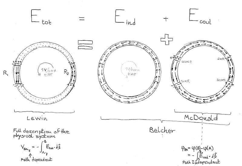
By the sheer power of superposition, we can mathematically decompose the total electric field Etot into its two components Ecoul and Eind.

Etot = Ecoul + Eind

The first is the conservative (or irrotational, or laminar) part that is due to the coloumbic force, while the latter is the nonconservative (or rotational, or solenoidal) induced electric field associated with the changing magnetic flux. Since integrals are linear operators, we can split the path integral that expresses voltage in two contributes


Now, the conservative part of the electric field Ecoul admits a potential function that we call the electric scalar potential phi (I am using this notation on purpose to make it clear it is not the non-existent potential function for the total electric field Etot), so we can express that component of voltage as a scalar potential difference phi(B) - phi](A) = phiB - phiA = phiBA


Here I made the signs explicit, so that it is clear that the actual path-dependent voltage V - the one Ohm's law works with - is the sum of two components: the path-independent difference in electric scalar potential phiBA and the contribute of the inducted electric field (that can be expressed as a function of the magnetic vector potential A).
The partial component phiBA is the voltage that KVLers believe is the real and true voltage, and if we express it in this way


it is clear that we are subtracting a partial component from the actual 'full' voltage. VA->B = VBAgamma is the voltage that gives the full picture as it is expression of the one and only total electric field Etot that electrons and other charges can sense. While phiBA = phi(B) - phi](A) is just a partial component that gives you only half of the story.

As a side note, if we wish to make use of the magnetic vector potential A, the formulae become:


and (spoiler alert!)  this is the key to understand where that 'tiny batteries' model comes from.
Yeah, yeah, it's voltage sources since they are generally time-varying, but if we fix a particular instant in time we can represent them with battery symbols, they make it easier to see the polarities without cluttering the drawings.


The source(s) of confusion
Some textbook authors define voltage in the chapters for electrostatics as the difference in electric potential (because when there are no changing magnetic fields, using the conventions above we have VBAgamma = VBA = phiBA ). The problem with this approach is that instead of using a dedicated symbol such as phi for the electrostatic potential, they use V from the start - thereby allocating the symbol V for the path-independent voltage of electrostatics. Then, when they reach the quasi-static electrodynamics chapters they can't use V for the more general path-dependent voltage, and they are therefore forced to give two physical quantities to fully describe their systems (either V and A, or Ecoul and Eind). This is not a big deal, as long as one understands that in this context the path-independent component of voltage only gives a partial description of the physical system. The Helmoltz decomposition is well known and used in electrodynamics, but to completely describe your system you need to specify both the electric scalar potential \phi (that some authors call V) and the magnetic vector potential A.

  • Notaros says that explicitly on p. 277 of his 2010 "Electromagnetics" textbook, formula 6.43: E(t) = - dA/dt - grad V. He writes: "We see that both potentials are needed for E..."  and what V is we can see from eq. 6.18 on page 269: Eq = - grad V, where Eq is the conservative part of the electric field (Ecoul in my notation). In Notaros' notation V is the scalar electric potential , i.e. what I called phi above.

  • McDonald does so in his note on page 6: "In time-dependent situations, such as the present example, the electric field E is related to both the scalar potential[] V as well as to the vector potential A according to E = -grad V -dA/dt", same formula for decomposing the total electric field into the conservative and solenoidal components E = EV + EA. McDonald also goes the extra mile in acknowledging that he suggest to call 'voltage' the scalar potential difference (but he gets a little muddy with the terminology):
    "While some people designate the integral of E · dl from a to b as a 'voltage drop', we advocate calling this the EMF between points a and b, and that the “voltage drop” between points a and b be reserved to mean simply Va − Vb, the difference in the scalar potential between the two points". And one day, when Arrow, Farnell, Mouser, and the likes will sell voltmeters capable of reading the scalar potential difference, instead of the actual voltage, I am sure everybody will be happy to follow his advice.

  • Belcher does not even get into defining potentials, but he makes use of the Helmoltz decomposition because he gives both fields on the ring: Ecoulomb and Einduced. One field component alone is not enough to describe the system. Just look at the pictures. He just does not compute the voltage, possibly to keep a neutral position and not expose himself to any of the backlash that had hit Lewin by that time. Personally, I think he should have shown more courage.


    Source: Belcher's note available on Electroboom's channel

    Also note that Belcher, like Lewin, agrees that the resultant electric field in the wires is zero (for perfectly conducting wires): "This will leave us with no electric field in the wire, but electric fields in both resistors, and these are the electric fields we found above in (4), where we begin with the assumption that the current is the same everywhere in the circuit."

  • Feynman uses the scalar and vector potentials in a more general setting on p. 15-16 he writes:
    "once we have A and phi , we get B from curl A, as before, and E from −grad phi − dA/dt."
    Like all the others he knows you need both potentials to determine the electric field E. The one and only electric field that a charge can experience, and that obeys the local form of Ohm's law.

KVLers, on the other hand, believe that the scalar potential difference phiBA is the only one and true voltage between points A and B, and that if you obtain a different value then it must mean you are committing a probing error. No, probing has nothing to do with the fact that the scalar potential difference alone only gives a partial description of your physical system when variable magnetic fields are present. This partial description is also what is represented by the 'tiny batteries' model of inductive components. This model and why it represents only half of the story, is the subject of another post, but a sneak preview is contained in this picture:


« Last Edit: December 07, 2021, 04:53:22 am by Sredni »
All instruments lie. Usually on the bench.
 
The following users thanked this post: bsfeechannel, emece67

Offline bsfeechannelTopic starter

  • Super Contributor
  • ***
  • Posts: 1667
  • Country: 00
Re: #562 – Electroboom!
« Reply #663 on: December 05, 2021, 02:42:37 am »
If you don't trust what I said about the circuit equivalent of the resistors in the original one-loop ring, just build it, measure it, and post your results.

Look at the video posted by your fellow KVLer, fromjesse


He used big chunky 5W ceramic resistors, one is 150 Ω and the other is 47 Ω, 5% tolerance. The transformer is wound at about 200mV per turn, which gives you 1mA in the loop, and the voltages he measures are exactly what should be: around 150mV and 48 mV, respectively.

Man, I can't get enough of debunking your KVLer claims. And it's so easy since you KVLers provide all the evidence we need to.

« Last Edit: December 05, 2021, 12:53:39 pm by bsfeechannel »
 

Offline jesuscf

  • Frequent Contributor
  • **
  • Posts: 499
  • Country: ca
Re: #562 – Electroboom!
« Reply #664 on: December 05, 2021, 05:40:19 am »
If you don't trust what I said about the circuit equivalent of the resistors in the original one-loop ring, just build it, measure it, and post your results.

Look at the video posted by or fellow KVLer, fromjesse

He used big chunky 5W ceramic resistors, one is 150 Ω and the other is 47 Ω, 5% tolerance. The transformer is wound at about 200mV per turn, which gives you 1mA in the loop, and the voltages he measures are exactly what should be: around 150mV and 48 mV, respectively.

Man, I can't get enough of debunking your KVLer claims. And it's so easy since you KVLers provide all the evidence we need to.

What a coincidence that I just finished making a decent source to create a stronger varying magnetic field which allows for easier testing!

So, this what I just did:  I made a loop with a 100 ohms resistor to the left and a 900 ohms equivalent resistor to the right, just like in Lewin's experiment.  Except that the 900 ohm resistor to the right is made of nine 100 ohms resistors in series.   The voltage I measured in the single 100 ohm resistor is -42.4mV (using the same polarity as in Lewin's experiment).  That means that the voltage I would measure in a single 900 ohm resistor should be nine times that or 42.4*9=381 mV.  With those two voltages we can calculate a total induced EMF of 424 mV.

The radius of the ring is 8 cm.  That means that the perimeter is 2*pi*r or about 50 cm.  The nine 100 ohms resistors in series have a length of about 6.5 cm.  That means that the total induced EMF across the nine 100 ohm resistors in series should be about 55 mV.  With the voltage drop and the induced EMF in the nine 100 ohms resistors I can now calculate what I should measure between the terminals of the longer equivalent 900 ohm resistor: 381mv-55mv=326 mV.  For this 900 ohm resistor measurement, I had to be more careful not to pick up an induced voltage in the probing wires, so I used the setup shown in one of the attached pictures.

The voltage I measured is 332 mV! That is less than 2% error from the theoretical value of 326 mV!!!

EDIT: I uploaded one wrong picture, the last one, but I added the correct one in the next post.


« Last Edit: December 05, 2021, 06:08:22 am by jesuscf »
Homer: Kids, there's three ways to do things; the right way, the wrong way and the Max Power way!
Bart: Isn't that the wrong way?
Homer: Yeah, but faster!
 

Offline jesuscf

  • Frequent Contributor
  • **
  • Posts: 499
  • Country: ca
Re: #562 – Electroboom!
« Reply #665 on: December 05, 2021, 05:44:06 am »
In my previous post this image was not uploaded properly...
Homer: Kids, there's three ways to do things; the right way, the wrong way and the Max Power way!
Bart: Isn't that the wrong way?
Homer: Yeah, but faster!
 

Offline bsfeechannelTopic starter

  • Super Contributor
  • ***
  • Posts: 1667
  • Country: 00
Re: #562 – Electroboom!
« Reply #666 on: December 05, 2021, 12:04:41 pm »
For this 900 ohm resistor measurement, I had to be more careful not to pick up an induced voltage in the probing wires, so I used the setup shown in one of the attached pictures.

Cool! That's what I thought. Jesse measured the wrong voltage. He let his probes pick up induced voltage.

Thank you, jesuscf. We finally managed to show that Jesse's experiments are a hoax. No wonder he left the discussion. He knew he would be caught and exposed sooner or later by your imaginative intellect.
« Last Edit: December 06, 2021, 12:27:17 pm by bsfeechannel »
 

Offline Sredni

  • Frequent Contributor
  • **
  • Posts: 686
  • Country: aq
Re: #562 – Electroboom!
« Reply #667 on: December 06, 2021, 06:35:56 am »
This Lewin guy must be like one of those aliens from the movie "The Thing". He clearly brainwashed, or flat out replaced with his own clones, the whole of MIT.
I just found another EM textbook from MIT OCW that has the two resistors ring around a changing flux region... and it agrees with him.


It is also available online for free - surely a way to propagate these... How did Bob Duhamel of RSD Academy call these? "disagreeing with the vast majority of the scientific establishment, [...] disagreeing with the vast majority of textbooks, [...] disagreeing with the vast majority of professor of both electrical engineering and physics."

https://ocw.mit.edu/resources/res-6-002-electromagnetic-field-theory-a-problem-solving-approach-spring-2008/
https://ocw.mit.edu/resources/res-6-002-electromagnetic-field-theory-a-problem-solving-approach-spring-2008/about-this-book/
https://ocw.mit.edu/resources/res-6-002-electromagnetic-field-theory-a-problem-solving-approach-spring-2008/textbook-contents/

Not only Lewin must have brainwashed this author, but he clearly has a time machine because this textbook was published in 1979, even before Romer's paper. The sneaky little Dutch devil!

The Zahn-Romer-Lewin ring is in section "6.2.3: Transformer Action", "a) Voltages are not unique" (p. 411)


Edited to adjust a few sentences but mostly to fix the place of my 's'. I have developed a theory that the numbers of "s" in my posts is always correct. They are just scattered at random.


« Last Edit: December 06, 2021, 07:10:43 pm by Sredni »
All instruments lie. Usually on the bench.
 
The following users thanked this post: bsfeechannel, HuronKing

Offline jesuscf

  • Frequent Contributor
  • **
  • Posts: 499
  • Country: ca
Re: #562 – Electroboom!
« Reply #668 on: December 06, 2021, 06:49:21 am »
This Lewin guy must be like one of those aliens from the movie "The Thing". He clearly brainwashed the whole of MIT.
I just found another EM textbook from MIT OCW that has the two resistor rings around a changing flux region... and it agrees with him.
It is also available online for free - surely a way to propagate these... How did Bob Duhamel of RSD Academy call these? Nonstandard concepts that go against the science and engineering establishment? (I'll fetch the exact quote later).

https://ocw.mit.edu/resources/res-6-002-electromagnetic-field-theory-a-problem-solving-approach-spring-2008/
https://ocw.mit.edu/resources/res-6-002-electromagnetic-field-theory-a-problem-solving-approach-spring-2008/about-this-book/
https://ocw.mit.edu/resources/res-6-002-electromagnetic-field-theory-a-problem-solving-approach-spring-2008/textbook-contents/

Not only Lewin must have brainwashed this author, but he clearly has a time machine because this textbook was published in 1979, even before Romer's paper. The sneaky little Dutch devil!

The Zahn-Romer-Lewin ring is in section "6.2.3: Transformer Action", "a) Voltages are not unique" (p. 411)

At this point I am pretty sure you are just delusional.
Homer: Kids, there's three ways to do things; the right way, the wrong way and the Max Power way!
Bart: Isn't that the wrong way?
Homer: Yeah, but faster!
 

Offline Sredni

  • Frequent Contributor
  • **
  • Posts: 686
  • Country: aq
Re: #562 – Electroboom!
« Reply #669 on: December 06, 2021, 07:06:52 am »
This Lewin guy must be like one of those aliens from the movie "The Thing". He clearly brainwashed the whole of MIT.
I just found another EM textbook from MIT OCW that has the two resistor rings around a changing flux region... and it agrees with him.
It is also available online for free - surely a way to propagate these... How did Bob Duhamel of RSD Academy call these? Nonstandard concepts that go against the science and engineering establishment? (I'll fetch the exact quote later).

https://ocw.mit.edu/resources/res-6-002-electromagnetic-field-theory-a-problem-solving-approach-spring-2008/
https://ocw.mit.edu/resources/res-6-002-electromagnetic-field-theory-a-problem-solving-approach-spring-2008/about-this-book/
https://ocw.mit.edu/resources/res-6-002-electromagnetic-field-theory-a-problem-solving-approach-spring-2008/textbook-contents/

Not only Lewin must have brainwashed this author, but he clearly has a time machine because this textbook was published in 1979, even before Romer's paper. The sneaky little Dutch devil!

The Zahn-Romer-Lewin ring is in section "6.2.3: Transformer Action", "a) Voltages are not unique" (p. 411)

At this point I am pretty sure you are just delusional.

You are clearly entitled to your opinion, but out of sheer curiosity...
Delusional about what?
About the fact that Lewin is just one of many university professors who know that voltage is no longer unique when magnetic fields change?
About the fact that KVLers think he is a lone wolf, a rogue scientist with an alternative theory because they never actually studied EM at uni level, even undergrad level?
About the fact that Lewin is an alien? (This might have been an exaggeration on my part, I have to admit it)

All instruments lie. Usually on the bench.
 

Offline HuronKing

  • Regular Contributor
  • *
  • Posts: 230
  • Country: us
Re: #562 – Electroboom!
« Reply #670 on: December 06, 2021, 07:10:35 am »
This Lewin guy must be like one of those aliens from the movie "The Thing". He clearly brainwashed the whole of MIT.
I just found another EM textbook from MIT OCW that has the two resistor rings around a changing flux region... and it agrees with him.
It is also available online for free - surely a way to propagate these... How did Bob Duhamel of RSD Academy call these? Nonstandard concepts that go against the science and engineering establishment? (I'll fetch the exact quote later).

https://ocw.mit.edu/resources/res-6-002-electromagnetic-field-theory-a-problem-solving-approach-spring-2008/
https://ocw.mit.edu/resources/res-6-002-electromagnetic-field-theory-a-problem-solving-approach-spring-2008/about-this-book/
https://ocw.mit.edu/resources/res-6-002-electromagnetic-field-theory-a-problem-solving-approach-spring-2008/textbook-contents/

Not only Lewin must have brainwashed this author, but he clearly has a time machine because this textbook was published in 1979, even before Romer's paper. The sneaky little Dutch devil!

The Zahn-Romer-Lewin ring is in section "6.2.3: Transformer Action", "a) Voltages are not unique" (p. 411)

Obviously another 'bad prober.'  ;D

It's clear from Romer's paper that he had a crisis of conscience about KVL - he tells an amusing anecdote when he says he first learned about the non-uniqueness of voltages from Rogers and Shoemaker during an oral exam. I wonder if Lewin had a similar revelation which is why he says "Kirchoff is for the birds and Faraday is not." Unfortunately for Lewin, it also appears his biggest crime was saying "Kirchoff is for the birds, and Faraday is not."


Offline bsfeechannelTopic starter

  • Super Contributor
  • ***
  • Posts: 1667
  • Country: 00
Re: #562 – Electroboom!
« Reply #671 on: December 06, 2021, 02:00:29 pm »
The Zahn-Romer-Lewin ring is in section "6.2.3: Transformer Action", "a) Voltages are not unique" (p. 411)

Obviously another 'bad prober.'  ;D

Mehdi will say that Zahn is adherent to the "old definition of voltage" and that the majority of professors and authors now agree with his "new definition of voltage".

What is this new definition of voltage? It's one that makes Lewin look wrong and Mehdi look right before his audience comprised mostly of dimwits like himself.

When his audience realizes that he's wrong, he'll invent a new stupid explanation and he'll repeat it until it appears legitimized for them.

That's the same technique used by those who spread fake news. Truth sucks. Truth is boring. Truth requires evidence, rigor, proof. Telling you that to be a good engineer you will have to painstakingly study functions, calculus, vector calculus, Maxwell's equations sucks. Saying that, without any formal training in engineering in general and electromagnetism in specific, you can confront a seasoned engineering course professor and author at a respected technology institute is cool and takes no more than a 10 minute video quickly slapped together, intermingled with slapstick comedy jokes.

Quote
It's clear from Romer's paper that he had a crisis of conscience about KVL - he tells an amusing anecdote when he says he first learned about the non-uniqueness of voltages from Rogers and Shoemaker during an oral exam. I wonder if Lewin had a similar revelation which is why he says "Kirchoff is for the birds and Faraday is not." Unfortunately for Lewin, it also appears his biggest crime was saying "Kirchoff is for the birds, and Faraday is not."

No doubt. For many of us, the full implications of the electromagnetic phenomenon is a shocking event. One that gives room to the so called five stages to acceptance: denial, anger, bargain, depression and acceptance. At first there is an outright rejection, then a resistance. Resignation comes right before the acceptance of reality.

 
The following users thanked this post: HuronKing

Offline thinkfat

  • Supporter
  • ****
  • Posts: 2150
  • Country: de
  • This is just a hobby I spend too much time on.
    • Matthias' Hackerstübchen
Re: #562 – Electroboom!
« Reply #672 on: December 06, 2021, 03:03:57 pm »
It's actually much easier to cope with once you accept that the induced electric field is not IN the circuit. Then you stop looking for it and try modeling it with tiny batteries.
Everybody likes gadgets. Until they try to make them.
 

Offline jesuscf

  • Frequent Contributor
  • **
  • Posts: 499
  • Country: ca
Re: #562 – Electroboom!
« Reply #673 on: December 06, 2021, 03:27:31 pm »
This Lewin guy must be like one of those aliens from the movie "The Thing". He clearly brainwashed the whole of MIT.
I just found another EM textbook from MIT OCW that has the two resistor rings around a changing flux region... and it agrees with him.
It is also available online for free - surely a way to propagate these... How did Bob Duhamel of RSD Academy call these? Nonstandard concepts that go against the science and engineering establishment? (I'll fetch the exact quote later).

https://ocw.mit.edu/resources/res-6-002-electromagnetic-field-theory-a-problem-solving-approach-spring-2008/
https://ocw.mit.edu/resources/res-6-002-electromagnetic-field-theory-a-problem-solving-approach-spring-2008/about-this-book/
https://ocw.mit.edu/resources/res-6-002-electromagnetic-field-theory-a-problem-solving-approach-spring-2008/textbook-contents/

Not only Lewin must have brainwashed this author, but he clearly has a time machine because this textbook was published in 1979, even before Romer's paper. The sneaky little Dutch devil!

The Zahn-Romer-Lewin ring is in section "6.2.3: Transformer Action", "a) Voltages are not unique" (p. 411)

Obviously another 'bad prober.'  ;D

It's clear from Romer's paper that he had a crisis of conscience about KVL - he tells an amusing anecdote when he says he first learned about the non-uniqueness of voltages from Rogers and Shoemaker during an oral exam. I wonder if Lewin had a similar revelation which is why he says "Kirchoff is for the birds and Faraday is not." Unfortunately for Lewin, it also appears his biggest crime was saying "Kirchoff is for the birds, and Faraday is not."

Definitively another guy that doesn't understand that the voltage between nodes VAD depends only on the unique path of the original circuit, a circuit which is not changing shape or moving.  When measuring, the voltage the instrument displays depends on the path of the instrument wires, but that is not the voltage VAD, it is the voltage at the instrument!  With that understanding it is a trivial task to find the correct and unique voltage between nodes VAD which is independent of the path of the instrument wires.  So, how do you find the correct voltage between nodes 'A' and 'D', VAD?  Using KVL of course!
Homer: Kids, there's three ways to do things; the right way, the wrong way and the Max Power way!
Bart: Isn't that the wrong way?
Homer: Yeah, but faster!
 

Offline Sredni

  • Frequent Contributor
  • **
  • Posts: 686
  • Country: aq
Re: #562 – Electroboom!
« Reply #674 on: December 07, 2021, 05:20:22 pm »
Quote
https://ocw.mit.edu/resources/res-6-002-electromagnetic-field-theory-a-problem-solving-approach-spring-2008/
The Zahn-Romer-Lewin ring is in section "6.2.3: Transformer Action", "a) Voltages are not unique" (p. 411)
Definitively another guy that doesn't understand that the voltage between nodes VAD depends only on the unique path of the original circuit, a circuit which is not changing shape or moving. 

Of course. The MIT is notoriously known for its scarcely prepared professors of physics and engineering.
Here is yet another professor who does not understand the basics of electromagnetism!
Shame on you, MIT!!!
Listen to the guys in a garage, instead. They have an oscilloscope, so they clearly know what they are talking about.

Quote
When measuring, the voltage the instrument displays depends on the path of the instrument wires, but that is not the voltage VAD, it is the voltage at the instrument!  With that understanding it is a trivial task to find the correct and unique voltage between nodes VAD which is independent of the path of the instrument wires.  So, how do you find the correct voltage between nodes 'A' and 'D', VAD?  Using KVL of course!

I would love to see you get the voltage on the conductors that join the resistors in this square ring, asymmetrically placed inside a square toroidal core, by simply using KVL.
Keep in mind that the induced field Eind is no longer directed along concentric circles, and your ring is now square.
Good luck using KVL.

All instruments lie. Usually on the bench.


Share me

Digg  Facebook  SlashDot  Delicious  Technorati  Twitter  Google  Yahoo
Smf