And operating an unknown LED lamp from a PWM square wave is bad design, so there's a risk it will blow up.
Keywords here are dimmable LED bulb and LED bulb that tolerates triac dimmers. Please read below.
That's all fine, until the user replaces it with a non-dimmable lamp.
How is it wrong? If I made any errors, please point them out and correct them.
Error 1) You compared dissipation of each inrush limiter resistor without showing dissipation in each "LED equivalent" made out of current sink. For fair comparison they must be equal. So basically useless comparison.
Error 2) You compared 100% duty cycle (undimmed) AC mains to 50% duty cycle square wave. Again useless comparison.
What do you mean by LED equivalent? The power rating of one of the components is exceeding its rating by a factor of 5, when run on a 50% duty square wave vs the sine wave it was designed for!
Bear in mind there are lots of different LED lamp designs. . .
Right. Those which will fail from leading-edge mode triac dimmer input most likely will fail from square wave too.
I agree so perhaps my simulation, wasn't so incorrect after all. It demonstrates why a non-dimmable LED will fail, when operated from PWM.
- As I said already multiple times that "Proper dimmable square wave inverter will not blow up LED bulbs faster than triac dimmers."
Here's another mains powered LED lamp design. This time I've posted the full schematic.
Well, thank you. For balance I will share one much more interesting - from engineering point of view.
https://www.fairchildsemi.com/product-technology/direct-ac-drive/
No, there is a risk it will blow up. Suppose the circuit can safely run off 230VDC safely, without any problems, it does not mean that it can run off 230V with 50% PWM safely. Every time the power is applied, a large current flows through the surge suppression resistor to charge the capacitor. The bulb will only be designed to be turned on occasionally, not turned on and off, from an abrupt square wave hundreds of times per second.
When dimmed from leading edge mode triac, sharp pulse up-to full Peak-Peak voltage of AC mains each half-cycle will be applied to it while at particular dimmer setting:

Further reading:
http://www.ledsmagazine.com/articles/print/volume-8/issue-6/features/led-lighting-must-work-with-legacy-dimming-technologies-magazine.html
PWM is only good for controlling the power delivered to linear loads such as resistors and motors. It is no good for non-linear loads, such as switched mode power supplies, which are often found in modern LED lamps.
That one particular LED bulb controller you gave datasheet for, does support triac dimmers, both leading and traling edge. Hows that?
It supports TRIAC dimmers, not PWM! They are not the same thing!
Ok it might not blow up but flicker, when run off the wrong frequency square wave, rather than a sine wave. Still not good.
Why not simply use a 50 or 60Hz sine wave inverter and a proper dimmer circuit for a dimmable LED lamp, rather than risking failure with a square wave, at the wrong frequency? That's a much better solution. Use components, as they're designed to be used, within their specifications. Attempting otherwise, only leads to trouble, further down the road.
By the way, thank you for posting the second link. It might help to explain to the original poster, why his LEDs aren't getting any dimmer.
You are kidding me or what? Please re-read it carefully: "tune peak voltage so LEDs dissipate identical power compared to AC sinewave design and only then check power dissipation in the inrush limiter resistor".
And how are you going to check the power dissipation in the inrush limiter, inside the LED bulb, without dismantling it?
Crlt+click on waveform 
Yes, I did talk about your LTspice simulation, not LED physical bulb.
What do you mean by?
Please re-read it carefully: "tune peak voltage so LEDs dissipate identical power compared to AC sinewave design and only then check power dissipation in the inrush limiter resistor".
I re-read it several times and it makes no sense!
The LTSpice simulation was an approximation of an LED driver circuit, run off a bridge rectifier and capacitor. The LED is modelled as a current source, but in reality, it will be a constant power circuit, i.e. a switched mode power supply. The input current will increase, as the voltage on the capacitor falls (down to a certain point of course) which should theoretically, increase the power dissipation on the surge limiting resistor, as the supply voltage is reduced. The end result will be the same: PWMing it will cause no dimming and premature failure.
arduino will be retired  to cut cost , adding bjt /555 later
yes , IC on right is 4017
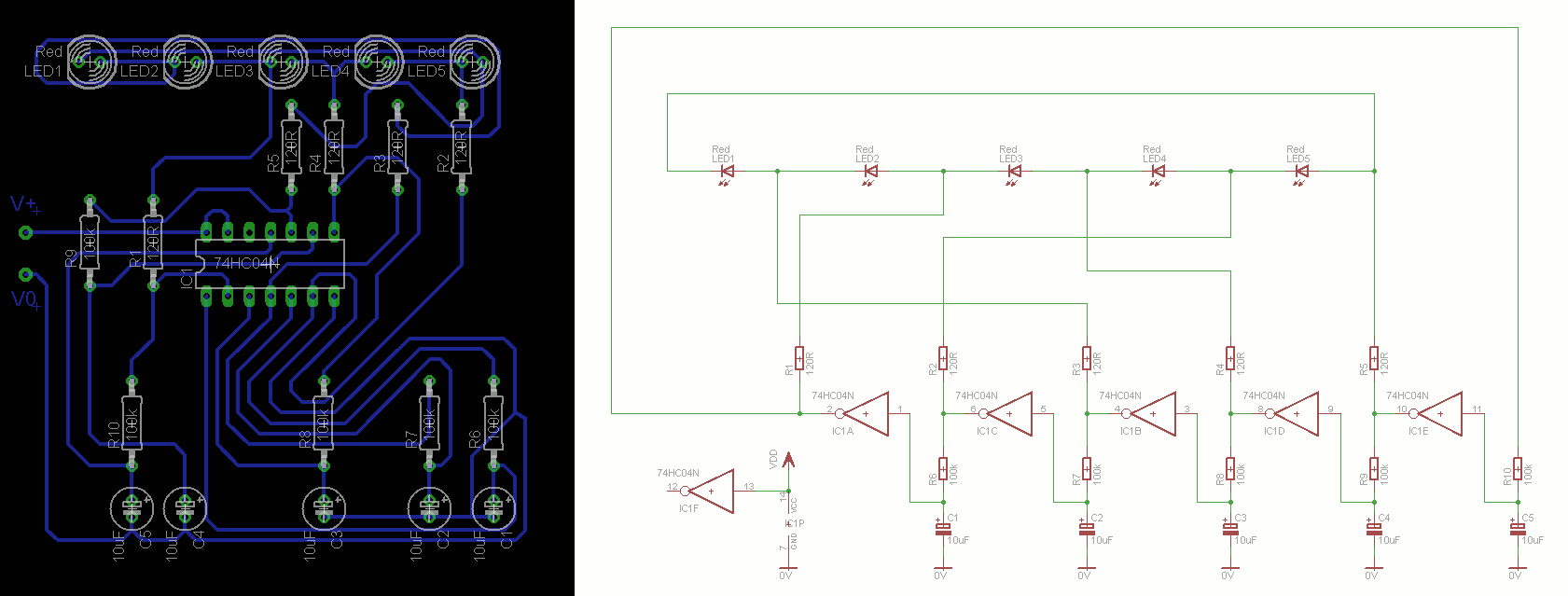
Another option is a ring oscillator. I designed a PCB for one awhile ago, as a learning exercise.
 https://www.eevblog.com/forum/beginners/my-latest-eagle-pcb/msg10497/#msg10497
By the way, no that would not make mains LEDs use less energy, but keep the brightness the same. They will either get dimmer, or the controller IC inside the mains LED lamp, will increase the current draw, to keep the brightness constant. If the latter happens, there's more risk of premature failure of the LEDs or inverter, used to drive them. You need to invest in a power meter. One which will work with a square wave and at different frequencies than the standard 50 or 60Hz mains. Measuring the voltage and current simultaneously and applying Ohm's law doesn't give you the true power, although it will give you a good idea of whether the inverter's output current rating is not being exceeded.
I have a non-dimmable mains LED lamp. I've tried using it with a phase controlled dimmer. The brightness stays constant, until the dimmer setting is reduced past a certain point, then it starts flickering and stops working. I have not measured the power consumption with the dimmer, but I'm pretty sure that it's not using less power, with the dimmer, than without it. I didn't test it for long, because it's likely it would have damaged the dimmer.
for people with interest the johnny aum night light. is an example of getting very nice light with 51Milliwatts power, driven LED is 2.8watts ! Point is there are many possibilities
http://www.energeticforum.com/296163-post38.html?s=03f790b602cb7fbdb175e0416c3a83d4
That looks like a Joule thief. A very old circuit. It's totally different to what you're doing, because the LED's driver has been removed, so it's powering a bare LED. That circuit doesn't magic 2.759W from nowhere! The 2.8W bulb is clearly running at a fraction of its rating brightness, because the current through it is much lower than the rating. It's true that driving an LED, at a lower current, than its maximum rating increases the efficiency, up to a certain point, but it works out very expensive to buy LEDs rated for much more power, than they'll be driven with, so LED manufacturers won't do it. How many people would by a 1W LED which costs nearly as much as a 10W LED?


