Author Topic: Advice on how to reverse the output of a frequency divider?  (Read 3020 times)

0 Members and 1 Guest are viewing this topic.

Offline ArthrimusTopic starter

  • Newbie
  • Posts: 3
  • Country: us
Advice on how to reverse the output of a frequency divider?
« on: September 27, 2017, 03:48:22 am »
tl:dr I need some way to flip high to low and low to high on the output of a 74ls393 running as a frequency divider. The circuit I'm trying to build needs to have two select lines pulsed in a specific order and currently I'm getting the exact reverse of pulse order that I need. Either I need an extra component to do this or perhaps there is a a part that can do this naively that could replace the 74ls393 entirely?

Hello, this is my first post here so I wanted to start off by saying thanks for providing such a fine resource to budding electronic hobbyists such as myself. Now I've finally gone ahead and joined this forum for probably the same reason that most do, which is to put it simply, I'm stumped.

So here's a quick overview of what I'm trying to do. I am trying to build a variation of this circuit here:


This circuit functions as a demuxer for Sega Saturn control pads and gives discrete outputs from button presses on the controller. Now as is this circuit does actually work with official Sega Saturn control pads which are simply made of a pair of 74hc153A dual 4 in 1 out multiplexers. The issue that I'm having has to do with using a non standard controller with this same circuit, in this case the microcontroller based MC Cthulhu arcade board. This board is meant for connecting arcade joysticks and buttons to multiple game consoles including the Sega Saturn. It simply emulates the protocol of whatever game console it is connected to at the time. The problem that I am having is that when MC Cthulhu is connected my button mapping is reversed for two of the four possible states of the select lines. Here is a table of the bit assignments for the Saturn controller:


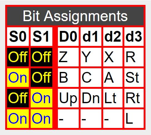
In my case the outputs are flipped for "S0 off S1 off", and "S0 off S1 on". The other two combinations work fine. After probing both a real Sega Saturn and my circuit I uncovered why those two states are being flipped. It's because the MC Cthulhu takes a shortcut in it's programming. Now I'm not 100% sure how the MC Cthulhu works because it's designer went AWOL a couple of years ago and nobody else seems to have any insight into how it works under the hood, but based off it's behavior in my testing it seems that the Cthulhu doesn't actually read each pulse from each select line and send the correct output for that pulse. Instead since it was developed only to work with the Sega Saturn which has a known specific pulse order I think it simply has a predetermined order of outputs that it sends every full select pulse cycle regardless of what order it is receiving the select pulses. Here is a look at how a real Saturn console pulses these select lines. S0 is channel 1 and S1 is channel 2:


And here is how the circuit above pulses the select lines. Same as before S0 is channel 1 and S1 is channel 2:


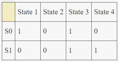
The duty cycle is really weird on the saturn but I don't think that's a concern. The real concern is that these two circuits pulse in exactly the opposite order. I've made a couple of tables to make it easier to visualize.

Original Sega Saturn Hardware:


Saturn pad Demuxer


As you can see states 2 and 4 are flipped. So all of this to say, what I need is to reverse the output waveforms high to low and low to high so they pulse the select lines in the correct order. Is there an equivalent binary counter that will give me the reverse of this output instead of the 74ls393, or is there additional circuitry that would give me the desired effect? Any advice is greatly appreciated.
 

Offline Brumby

  • Supporter
  • ****
  • Posts: 12297
  • Country: au
Re: Advice on how to reverse the output of a frequency divider?
« Reply #1 on: September 27, 2017, 09:01:19 am »
Does inverting the S0 signal give you the desired result?
 

Offline Ian.M

  • Super Contributor
  • ***
  • Posts: 12855
Re: Advice on how to reverse the output of a frequency divider?
« Reply #2 on: September 27, 2017, 09:25:55 am »
Just swap the pins you need at the /Yn outputs of the 74LS138.
 

Offline ArthrimusTopic starter

  • Newbie
  • Posts: 3
  • Country: us
Re: Advice on how to reverse the output of a frequency divider?
« Reply #3 on: September 27, 2017, 11:16:39 am »
Does inverting the S0 signal give you the desired result?
Yes, now that I look at it inverting just the S0 signal should also give the desired result.  Do you have an idea for how I might do that? 

Just swap the pins you need at the /Yn outputs of the 74LS138.
Yes, I had thought of that,  but unfortunately that would just result in the same mapping issue with official Saturn pads. I would like the circuit to work properly with both of I can.
 

Offline Ian.M

  • Super Contributor
  • ***
  • Posts: 12855
Re: Advice on how to reverse the output of a frequency divider?
« Reply #4 on: September 27, 2017, 12:21:38 pm »
Only one half of the 74LS393 is used, so it could be replaced with a single counter instead of a dual one.   To match the Saturn sequence, you need a down counter not an up counter.  I would suggest replacing the 74LS393 with a 74LS193 up/down counter, with the 555 clock to the Down input and all other inputs pulled high.
 
The following users thanked this post: Arthrimus

Offline Brumby

  • Supporter
  • ****
  • Posts: 12297
  • Country: au
Re: Advice on how to reverse the output of a frequency divider?
« Reply #5 on: September 27, 2017, 01:57:04 pm »
If you want to simply invert S0, then I would just add in another chip.  Just a simple gate chip would do ... one with an inverted output - NAND, NOR or a straight out Inverter.
 
The following users thanked this post: Arthrimus

Offline ArthrimusTopic starter

  • Newbie
  • Posts: 3
  • Country: us
Re: Advice on how to reverse the output of a frequency divider?
« Reply #6 on: September 28, 2017, 03:57:42 am »
Only one half of the 74LS393 is used, so it could be replaced with a single counter instead of a dual one.   To match the Saturn sequence, you need a down counter not an up counter.  I would suggest replacing the 74LS393 with a 74LS193 up/down counter, with the 555 clock to the Down input and all other inputs pulled high.
That makes sense to me, I'll order some 74ls193s and see how that works. Thanks for the help.

If you want to simply invert S0, then I would just add in another chip.  Just a simple gate chip would do ... one with an inverted output - NAND, NOR or a straight out Inverter.

I had a 74ls00 in the parts bin so I wired it up here like you suggested and it works. With the pulses in the correct sequence the MC Cthulhu works properly on this converter so it seems my assumptions about how it works were largely correct. Thanks for the help I'm a little out of my depth when it comes to circuits like this, I've really only ever worked on analog audio stuff so I'm not too familiar with logic gates and the like.
 

Offline Brumby

  • Supporter
  • ****
  • Posts: 12297
  • Country: au
Re: Advice on how to reverse the output of a frequency divider?
« Reply #7 on: September 28, 2017, 07:01:48 am »
That's good to hear.

Just one thing ... if you are using a 74LS00, then for the gate you are using, you need to tie both input pins to the input signal or one to the input signal and the other taken high.  Floating inputs are not to be relied upon for any logic chip for that matter.

For the same reason, it is generally recommended that the unused inputs of the gates you are not using are tied high or low - just to make sure there isn't any "indeterminate" input that may cause random switching in those gates.
« Last Edit: September 28, 2017, 07:03:51 am by Brumby »
 

Offline Ian.M

  • Super Contributor
  • ***
  • Posts: 12855
Re: Advice on how to reverse the output of a frequency divider?
« Reply #8 on: September 28, 2017, 07:24:20 am »
Unused inputs should either be tied high or low depending on the desired function

Bipolar TTL should always have unused inputs tied high via a pull-up resistor.  Otherwise there is a risk of latchup.   You can use one resistor for multiple inputs.

CMOS logic, (including 'TTL' compatible 74HC, 74HCT, 74AC etc.) can have its inputs tied high directly to VDD.   

Both bipolar TTL and CMOS logic can have inputs tied low directly to 0V.
« Last Edit: September 28, 2017, 07:32:33 am by Ian.M »


Share me

Digg  Facebook  SlashDot  Delicious  Technorati  Twitter  Google  Yahoo
Smf