Author Topic: Art of Electronics - Study support  (Read 10827 times)

0 Members and 1 Guest are viewing this topic.

Offline alex_palvaiTopic starter

  • Contributor
  • Posts: 40
  • Country: ca
Re: Art of Electronics - Study support
« Reply #75 on: May 14, 2020, 10:58:44 pm »
I've done the same simulation in Falstad and Vout is accurate there( attached screenshot ) . Confirms LTspice is culprit.
 

Offline vk6zgo

  • Super Contributor
  • ***
  • Posts: 7589
  • Country: au
Re: Art of Electronics - Study support
« Reply #76 on: May 14, 2020, 11:54:21 pm »
OP:-

Rectifier circuits are normally explained using sine waves.
The moment you start hitting them with square waves with a fairly fast risetime, the facts of life intervene.

Diodes are not perfect, and a reverse biased diode looks like a capacitor .
You can approximate this, in an (unachievable) circuit  using perfect components, by imagining a small capacitor connected in parallel with the diode.

The result will be that the diode does not "clip" the high frequency component of the fast rising square wave.
In this respect, it looks as if LTspice is actually doing its job.

That said, there are different types of diode optimised for different applications---with some, the capacitance in the reverse biased direction is minimal, & others it is quite high, because other parameters are regarded as more important in tne suggested applications.

You say you have a DSO &.function generator----- look at real world circuits rather than simulations, think about how circuits should work, why they are a bit different from what you expected, & so on.

Another thing which would be nice would be if you could find some old transformer type ac "wall warts" & using their low voltage secondaries, build  a few rectifier circuirs using real Mains frequencies

The explanations in the text you have shown are horribly "clunky".
I would suggest reading the "ARRL Handbook" (especially the older editions) to get a better idea of what your existing text is trying to communicate.
 
The following users thanked this post: alex_palvai

Offline alex_palvaiTopic starter

  • Contributor
  • Posts: 40
  • Country: ca
Re: Art of Electronics - Study support
« Reply #77 on: May 15, 2020, 02:07:30 am »
OP:-

Rectifier circuits are normally explained using sine waves.
The moment you start hitting them with square waves with a fairly fast risetime, the facts of life intervene.

Diodes are not perfect, and a reverse biased diode looks like a capacitor .
You can approximate this, in an (unachievable) circuit  using perfect components, by imagining a small capacitor connected in parallel with the diode.

The result will be that the diode does not "clip" the high frequency component of the fast rising square wave.
In this respect, it looks as if LTspice is actually doing its job.

That said, there are different types of diode optimised for different applications---with some, the capacitance in the reverse biased direction is minimal, & others it is quite high, because other parameters are regarded as more important in tne suggested applications.

You say you have a DSO &.function generator----- look at real world circuits rather than simulations, think about how circuits should work, why they are a bit different from what you expected, & so on.

Another thing which would be nice would be if you could find some old transformer type ac "wall warts" & using their low voltage secondaries, build  a few rectifier circuirs using real Mains frequencies

The explanations in the text you have shown are horribly "clunky".
I would suggest reading the "ARRL Handbook" (especially the older editions) to get a better idea of what your existing text is trying to communicate.

vk6zgo ,

Nice meeting you. Thanks for good explanation with lot of tips for learning , its all very motivating . I ordered but haven't received my function generator yet :-) (hopefully will get it next week ) . I worked a simulation of power supply circuit before trying this one and it didn't give me much trouble or WimberleyTech saved me a bit of trouble I had understanding some theory. Yes , I realized very soon that simulations are not giving me real world practical sense therefore going to rely more on hands on going forward.

And thank you for feedback on explanation in text and suggestions on "ARRL Handbook" . Will add it into my library. 
« Last Edit: May 15, 2020, 02:09:11 am by alex_palvai »
 

Offline Wimberleytech

  • Super Contributor
  • ***
  • Posts: 1133
  • Country: us
Re: Art of Electronics - Study support
« Reply #78 on: May 15, 2020, 04:20:52 pm »
I've done the same simulation in Falstad and Vout is accurate there( attached screenshot ) . Confirms LTspice is culprit.

I would not trust Falstad for anything but a simplistic analysis.

Consider the following.

When a diode is forward biased, the depletion region shrinks to a very small (relative value).  When you instantaneously reverse bias it, those charges take time to move away from the pn junction.  In the mean time, the capacitance across the diode is much higher than when steady state reverse bias.  I think that the reverse recovery time specification of a diode captures this feature. 

So, the glitch has nothing to do with reverse current and all to do with a very non-linear capacitance.
 
The following users thanked this post: alex_palvai

Offline Wimberleytech

  • Super Contributor
  • ***
  • Posts: 1133
  • Country: us
Re: Art of Electronics - Study support
« Reply #79 on: May 15, 2020, 09:16:32 pm »
I've done the same simulation in Falstad and Vout is accurate there( attached screenshot ) . Confirms LTspice is culprit.

I would not trust Falstad for anything but a simplistic analysis.

Consider the following.

When a diode is forward biased, the depletion region shrinks to a very small (relative value).  When you instantaneously reverse bias it, those charges take time to move away from the pn junction.  In the mean time, the capacitance across the diode is much higher than when steady state reverse bias.  I think that the reverse recovery time specification of a diode captures this feature. 

So, the glitch has nothing to do with reverse current and all to do with a very non-linear capacitance.

There you go!  1n4148 in this test.
 
The following users thanked this post: alex_palvai

Offline alex_palvaiTopic starter

  • Contributor
  • Posts: 40
  • Country: ca
Re: Art of Electronics - Study support
« Reply #80 on: May 16, 2020, 11:09:00 pm »
I've done the same simulation in Falstad and Vout is accurate there( attached screenshot ) . Confirms LTspice is culprit.

I would not trust Falstad for anything but a simplistic analysis.

Consider the following.

When a diode is forward biased, the depletion region shrinks to a very small (relative value).  When you instantaneously reverse bias it, those charges take time to move away from the pn junction.  In the mean time, the capacitance across the diode is much higher than when steady state reverse bias.  I think that the reverse recovery time specification of a diode captures this feature. 

So, the glitch has nothing to do with reverse current and all to do with a very non-linear capacitance.

There you go!  1n4148 in this test.

Thanks to all of you for correcting me. I almost went into wrong assumptions and thought those were right.

Wim. Thanks for good explanation of what's happening and taking time to run trace for me. Really greatful.

With all your guidance i moved forward and perfected my circuit on LtSpice by correcting ( Trise & Tfall) - Rstofer pointed it right in his first response but it didn't strike me that moment why its behaving that way.

I have a better understanding of diodes and signal rectifier circuits now than yesterday. I documented all my test cases and notes . One thing didn't strike me still and am trying to figure out since an hour why my circuit is not displaying forward voltage drop of .7V . Appreciate if someone can throw me light . I am trying to test the trick he gave wherein diode D1 compensates D2's forward voltage drop in this circuit . But without seeing the forward drop its a dead end.

Thanks in Advance for help.
 

Offline alex_palvaiTopic starter

  • Contributor
  • Posts: 40
  • Country: ca
Re: Art of Electronics - Study support
« Reply #81 on: May 30, 2020, 03:03:44 am »
Hello All,

Hope you all are doing good. I moved forward from the last question (the answer was when applied DC voltage you see clearly .6v drop and when AC voltage is applied its hard to see as but there is .545 volt drop ) . Was busy learning controls on  my newly purchased oscilloscope and function generator past week.

I landed on a new topic now " Frequency analysis of reactive circuits " and RC filters.  From what i read , low pass filters allow low frequencies and block high frequencies , opposite for high pass filters. My understanding is (0.001 - 50hz ) are low frequencies and high frequencies are (50 - above ) . And i tested same , i constructed a low pass filter with 100 ohm resistor and 100uF capacitor and noticed it passed frequencies from 1 - 50hz and blocked anything above 60hz. 

now mathematically i want to prove that point :

Reactance (Xc = 1/ ωC)
ω= 2πf
and my resistance R=100 ohm

at what point reactance Xc will be equal to equal to value of resistor ?

I know from my lab at f=60hz approx. is when  i almost see 99% signal is blocked .

Substituting same ,
=> 1/(2x(3.14)x60x100x10^-6)  => 26.53 (  I was expecting reactance this would show a value close to 100 )

Is my assumption correct that i should that value of reactance (Xc ) should be 100(=resistance) when capacitor blocks ?
« Last Edit: May 30, 2020, 05:00:56 am by alex_palvai »
 

Offline gcewing

  • Regular Contributor
  • *
  • Posts: 197
  • Country: nz
Re: Art of Electronics - Study support
« Reply #82 on: May 30, 2020, 11:50:22 am »
No, the frequency at which 99% of the input is blocked is considerably higher than the one where R = Xc.

Think of it as a voltage divider made from two impedances Z1 and Z2.
Then:

    Vout/Vin = Z2 / ( Z1 + Z2)

Here Z1 = 1/jwC and Z2 = R.

So if 1/wC = R, we have

    Vout/Vin = R / (R/j + r) = 1/(1 - j)

Draw a diagram of 1-j and you will see that it is a triangle with a hypotenuse of length sqrt(2), so

    Vout / Vin = 1/sqrt(2)

which is approximately 0.7. So the filter only blocks about 30% of the signal at this frequency.

What frequency is it? For the component values you gave,

    1/(2 pi f * 100uF) = 100 ohms

which gives

    f = 100 / 2 pi

which is about 16Hz.

Incidentally, the frequency at which Xc = R is known as the "-3dB point", because 20 * log10(1/sqrt(2)) is fairly close to 3.

It's also sometimes called the "cutoff frequency", but keep in mind that an RC filter doesn't suddenly cut off a this frequency, there is a fairly broad curve. It's just a mathematically convenient point to choose.
 
The following users thanked this post: alex_palvai

Offline rstofer

  • Super Contributor
  • ***
  • Posts: 9890
  • Country: us
Re: Art of Electronics - Study support
« Reply #83 on: May 30, 2020, 02:28:46 pm »
See Reply 52 in this thread for an example of a low pass filter and using an Analog Discovery 2 to draw the Bode' response.  There are 4 examples in that thread (starting with reply 52) that use the various features of the AD2 and just a simple resistor and capacitor.

The link takes you to Reply 50, scroll down a couple...

https://www.eevblog.com/forum/testgear/starter-scope/50/
« Last Edit: May 30, 2020, 02:38:26 pm by rstofer »
 
The following users thanked this post: alex_palvai

Offline alex_palvaiTopic starter

  • Contributor
  • Posts: 40
  • Country: ca
Re: Art of Electronics - Study support
« Reply #84 on: June 06, 2020, 07:08:23 pm »
having hard time understanding dB plotting .

the left side scale shows 0.001 to 1 on y-axis . Wondering how 6dB / octave or 20dB / decade were converted from dB to range  on y-axis from  (0.001 to 1 ) .
 

Offline Wimberleytech

  • Super Contributor
  • ***
  • Posts: 1133
  • Country: us
Re: Art of Electronics - Study support
« Reply #85 on: June 06, 2020, 08:29:38 pm »
having hard time understanding dB plotting .

the left side scale shows 0.001 to 1 on y-axis . Wondering how 6dB / octave or 20dB / decade were converted from dB to range  on y-axis from  (0.001 to 1 ) .

Does this help?

What I am really showing is dBV which is dB relative to 1 volt.
« Last Edit: June 06, 2020, 09:02:27 pm by Wimberleytech »
 
The following users thanked this post: alex_palvai

Offline alex_palvaiTopic starter

  • Contributor
  • Posts: 40
  • Country: ca
Re: Art of Electronics - Study support
« Reply #86 on: June 06, 2020, 09:09:47 pm »
having hard time understanding dB plotting .

the left side scale shows 0.001 to 1 on y-axis . Wondering how 6dB / octave or 20dB / decade were converted from dB to range  on y-axis from  (0.001 to 1 ) .

Does this help?

What I am really showing is dBV which is dB relative to 1 volt.

Hello Wim. Thank You . It helped 50% in understanding 20 dB per decade . Can you help me understanding 6dB / Octave on this same plot please.
 

Offline Wimberleytech

  • Super Contributor
  • ***
  • Posts: 1133
  • Country: us
Re: Art of Electronics - Study support
« Reply #87 on: June 06, 2020, 09:21:07 pm »
having hard time understanding dB plotting .

the left side scale shows 0.001 to 1 on y-axis . Wondering how 6dB / octave or 20dB / decade were converted from dB to range  on y-axis from  (0.001 to 1 ) .

Does this help?

What I am really showing is dBV which is dB relative to 1 volt.

Hello Wim. Thank You . It helped 50% in understanding 20 dB per decade . Can you help me understanding 6dB / Octave on this same plot please.

An equation may make more sense.
 
The following users thanked this post: alex_palvai

Offline alex_palvaiTopic starter

  • Contributor
  • Posts: 40
  • Country: ca
Re: Art of Electronics - Study support
« Reply #88 on: June 06, 2020, 10:20:18 pm »
having hard time understanding dB plotting .

the left side scale shows 0.001 to 1 on y-axis . Wondering how 6dB / octave or 20dB / decade were converted from dB to range  on y-axis from  (0.001 to 1 ) .

Does this help?

What I am really showing is dBV which is dB relative to 1 volt.

Hello Wim. Thank You . It helped 50% in understanding 20 dB per decade . Can you help me understanding 6dB / Octave on this same plot please.

An equation may make more sense.

Understood now. If what i am thinking is right , you nailed my real question without directly answering(Don't know how to thank you for that)  . I was under impression decade to octave will change the x-axis (from currently its a factor of 10 to factor of 2) . So 6dB/ Octave and 20dB/ Decade is same reference point . We actually make changes to y-Axis not x-axis is what i understand .

I am typing this just for my future reference , so what i get is , irrespective of whether its octave or decade scales , slope will not change. If I want to read it in octave scale , i put 6dB per vertical block instead of 20dB ( attached what's in my mind ) .
 

Offline robsims

  • Regular Contributor
  • *
  • Posts: 243
  • Country: sr
Re: Art of Electronics - Study support
« Reply #89 on: June 07, 2020, 12:36:53 am »
If you want to study electronics, you need at least high school level math. You don't need to derive formulas with calculus etc., but you have to know how they work of course. I am a mechanical engineer  and i am self studying electronics. A book that is not heavy on math and i think is best for starters is Electronic Principals from Malvino and Bates. I am currently at the chapter where they explain JFET's
 

Offline Wimberleytech

  • Super Contributor
  • ***
  • Posts: 1133
  • Country: us
Re: Art of Electronics - Study support
« Reply #90 on: June 07, 2020, 01:34:54 am »


... irrespective of whether its octave or decade scales , slope will not change.

BINGO!! You got it!
 
The following users thanked this post: alex_palvai

Offline Wimberleytech

  • Super Contributor
  • ***
  • Posts: 1133
  • Country: us
Re: Art of Electronics - Study support
« Reply #91 on: June 07, 2020, 01:37:30 am »
If you want to study electronics, you need at least high school level math. You don't need to derive formulas with calculus etc., but you have to know how they work of course. I am a mechanical engineer  and i am self studying electronics. A book that is not heavy on math and i think is best for starters is Electronic Principals from Malvino and Bates. I am currently at the chapter where they explain JFET's

It is useful to know how a JFET works, but I would hazard to guess that JFETs appear in 1% or less of modern circuits.  Understand MOSFETs and BJTs.  Of the three/four terminal devices, these will suit you well.
 

Offline alex_palvaiTopic starter

  • Contributor
  • Posts: 40
  • Country: ca
Re: Art of Electronics - Study support
« Reply #92 on: June 14, 2020, 05:21:23 pm »
Driving issues : its given that when choosing R and C values for blocking capacitor application I need to pick  R value to be reasonable load i.e. not so small  that its hard to drive .

Circuit loading:
My understanding of circuit loading is that the circuit being driven will add more load on driving circuit.  So what will happen to circuits if more load is added , assuming the straight forward answer is smaller components with least resistance will blow up correct ?

question:
Why does picking small R value makes it hard to drive ?   These statements align with what I read about source resistance and circuit loading that I need to pick larger load resistance (10x times) the source resistance to avoid circuit loading . But its not explained even there why would it cause circuit to load and how ?

In water analogy if you allow more water on top (less resistance)and restrain at bottom(more loax resistance)there is problem , pipes may burst due to pressure.

Thinking loud
Smaller resistance passes more current and larger passes less current . Suggestion is small resistance on top (allow more current to pass) then 10x bigger resistance at bottom ( limit current ) through heat .
What happens if I don't?
More current is passed on the top and even more at bottom due to even smaller resistance.  So what? How does that load the circuit ?


« Last Edit: June 15, 2020, 12:54:33 am by alex_palvai »
 

Offline gfmucci

  • Regular Contributor
  • *
  • Posts: 75
  • Country: us
Re: Art of Electronics - Study support
« Reply #93 on: June 14, 2020, 08:52:18 pm »
Interesting question about "how much math, calculus, differentials, etc." is essential to advance in the hobby or profession of electronics.

It reminds me of the question I had in seminary:  Should we be required to learn to read and speak Greek and Hebrew, or is it ok to just learn how to use the tools that express the meanings?  I much preferred the second path because I suck at languages, and two semesters of that torture was more than I could stomach.  I went back to my day job.  The tools can be challenging enough, never mind trying to learn how the tools were made.

If you want to teach it, that may be another matter.
« Last Edit: June 14, 2020, 08:56:29 pm by gfmucci »
 
The following users thanked this post: alex_palvai

Offline Wimberleytech

  • Super Contributor
  • ***
  • Posts: 1133
  • Country: us
Re: Art of Electronics - Study support
« Reply #94 on: June 14, 2020, 11:12:09 pm »
Interesting question about "how much math, calculus, differentials, etc." is essential to advance in the hobby or profession of electronics.

It reminds me of the question I had in seminary:  Should we be required to learn to read and speak Greek and Hebrew, or is it ok to just learn how to use the tools that express the meanings?  I much preferred the second path because I suck at languages, and two semesters of that torture was more than I could stomach.  I went back to my day job.  The tools can be challenging enough, never mind trying to learn how the tools were made.

If you want to teach it, that may be another matter.
...for it is God at work in you, both to will and to work for His good pleasure...
 

Offline alex_palvaiTopic starter

  • Contributor
  • Posts: 40
  • Country: ca
Re: Art of Electronics - Study support
« Reply #95 on: June 16, 2020, 10:41:20 pm »
I am assuming something , but want to make sure that's right.

For the problem in attached reference " Imaging putting 1uF Cap across 115 Volt (rms) 60 Hz powerline ? what's current flow was the question.

I understand how the current was derived .  But i don't understand how based on the result one can say which one is leading what "Current leading voltage or voltage leading current and by what angle "

My assumption is Given "Voltage" was taken as cosine i.e. 90 degrees before time t=0 begins ( please correct me if i am wrong ) , and the resultant current I came out to be sine (wt) i.e. crosses point t=0 . Therefore voltage is leading current .  Is that correct ?   (Given in text is opposite i.e. " Current leading voltage". Or is my assumption that cost will always start at 90 degrees before t=0 is incorrect ?

I tried to draw phasor diagram of this current and voltage, I was a bit skeptical to about the current on positive x-axis as the result i received was negative -0.6sine(wt). I made two representations , Appreciate if some one can guide to say which one is right one.. 


C=1F
v(t) = Acos(wt)
A= 115/root(2) rms volts
v(t) = 163cos(wt)

Ic= C*dv/dt
=>  10^-6 * d ( 163cos(wt) )
=>  10^-6 *w*A*-sin(wt)
=> 10^-6 * 6.2*60*163 =
=>-0.06sin(wt)
« Last Edit: June 17, 2020, 12:11:52 am by alex_palvai »
 

Offline vk6zgo

  • Super Contributor
  • ***
  • Posts: 7589
  • Country: au
Re: Art of Electronics - Study support
« Reply #96 on: June 29, 2020, 10:18:39 am »
I am assuming something , but want to make sure that's right.

For the problem in attached reference " Imaging putting 1uF Cap across 115 Volt (rms) 60 Hz powerline ? what's current flow was the question.

I understand how the current was derived .  But i don't understand how based on the result one can say which one is leading what "Current leading voltage or voltage leading current and by what angle "

My assumption is Given "Voltage" was taken as cosine i.e. 90 degrees before time t=0 begins ( please correct me if i am wrong ) , and the resultant current I came out to be sine (wt) i.e. crosses point t=0 . Therefore voltage is leading current .  Is that correct ?   (Given in text is opposite i.e. " Current leading voltage". Or is my assumption that cost will always start at 90 degrees before t=0 is incorrect ?

I tried to draw phasor diagram of this current and voltage, I was a bit skeptical to about the current on positive x-axis as the result i received was negative -0.6sine(wt). I made two representations , Appreciate if some one can guide to say which one is right one.. 


C=1F
v(t) = Acos(wt)
A= 115/root(2) rms volts
v(t) = 163cos(wt)

Ic= C*dv/dt
=>  10^-6 * d ( 163cos(wt) )
=>  10^-6 *w*A*-sin(wt)
=> 10^-6 * 6.2*60*163 =
=>-0.06sin(wt)

No, you can't go before t=0.
In the Universe where this question lives, there is no time before t=0.


Offline MuseChaser

  • Contributor
  • Posts: 30
  • Country: us
Re: Art of Electronics - Study support
« Reply #97 on: February 22, 2022, 08:46:17 pm »
Greetings, all.  I just registered because...well... I haven't felt this stupid in a long time, maybe ever, and need some help I guess.  I've been building kits, doing some limited speaker and crossover design and building, board repopulations, etc., for decades, and can kind of read a schematic to the point where I know the components I'm looking at and how they're connected, but I know precious little, if anything, about actual electronic engineering or design theory.  Sooo.. after getting stuck on trying to solve an issue on a Dynaco SCA80Q on my bench right now, I figured it's never too late to learn.  Bought a copy of AoE 2nd ed from Goodwill in great shape, and downloaded the accompanying student handbook and started the journey.  I have a headache.  At one time, I got as far as Calc BC, but that was back in the early 80s and I haven't done anything since other than routine "How many sheets of plywood do I need to build a 4x16 table?" .. Ok, maybe a bit more than that. I'm embarrassed by how much I've forgotten.


Anyway... Here's today's conundrums, still in the very basic parts of the books, dealing with Ohm's law (that, at least, I'm comfortable with), Kirchhoff's voltage and current laws (pretty OK there), Thevenin equivalences (so far, so good)... but I'm hitting a wall with some examples in the student handbook. 

For instance...
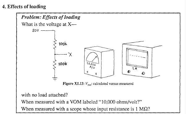

I thought I had this.. the original diagram on the left becomes a Thevenin reduction to a 10v source into a 50K resistor.  The meter's 10,000ohm/1V spec returns a current of 0.1mV. Using R=V/I to solve for internal resistance when reading 10v, we get an R value of 100K. Since that is 2/3 of the now total resistance (150K ...50k resulting from the Thevenin depiction of the divider circuit plus the 100K internal resistance), then the voltage at X when measured with the VOM labeled 10,000 ohms/V would be 6.6666 or, 6.7 as depicted. Check. I get it.

HOWEVER.. when connected to the scope w/ 1 MOhm input resistance, I a can't figure how they get the 9.5V result.   Since the input resistance is given w/out respect to voltage, is it constant on a 'scope, or do you still use I=V/R to calculate I=1V/1Mohm, resulting in 0.001mA? Then... as before... R=V/I = 10/0.000001 = 10M resistance, which is 0.995 of the total resistance, 10,050,000.  Wouldn't that yield a voltage reading of 9.95, and not 9.5 as suggested in the answer below?


Another question that stumped me -

1422256-2

Reducing the figure on the left to a Therevin equivalent easily yields the 11K result for the series resistors on top and .91 for the parallel on the bottom... all good there. However, isn't the resulting voltage at the dividing point equivalent to the results obtained from R1*R2/(R1+R2) for the resulting resistances? 11k*0.91k/11.91k yields 0.84V, not 0.74 as indicated. If I use the ratio method, lower resistance against total resistnace, or 0.91/11.91, I DO get .076, which then multiplied by the 10V input DOES yield the expected 0.76, but I don't understand why the other formula doesn't work in this case.

I know.. for all of YOU folks, this is like trying to explain to a two-year-old why 2+2 does not equal five, but it's been a VERY long time.  Hopefully, the rust will dissipate quickly.  Thanks in advance!
 

Offline Wimberleytech

  • Super Contributor
  • ***
  • Posts: 1133
  • Country: us
Re: Art of Electronics - Study support
« Reply #98 on: February 22, 2022, 09:35:20 pm »
In the case of the scope, it is just a fixed 1Mohm load.  So your voltage divider is 1M/(50k+1M) = 0.9524

For your other problem, do not rely on a formula.  Go back to first principles of ohms law.  Add the total resistance in series.  Divide that into the 10 volts.  That gives you current.  Then multiply that current by the lower resistance to get the voltage across it.  If you do this exercise symbolically, you will arrive at the correct symbolic formula.
« Last Edit: February 22, 2022, 09:41:00 pm by Wimberleytech »
 
The following users thanked this post: MuseChaser

Offline rstofer

  • Super Contributor
  • ***
  • Posts: 9890
  • Country: us
Re: Art of Electronics - Study support
« Reply #99 on: February 22, 2022, 10:13:19 pm »
When a V-O-M says 10k Ohms/Volt, it means 'volts full scale'.  If you are on a 1V scale, the input resistance is 10k * 1v or 10k Ohms.  If you are on a 20V scale, the input resistance is 10k * 20 or 200K Ohms.  So, without being told what scale the meter is set to, it isn't really possible to get the right answer.

A better explanation is here:

https://www.allaboutcircuits.com/textbook/direct-current/chpt-8/voltmeter-impact-measured-circuit/


Share me

Digg  Facebook  SlashDot  Delicious  Technorati  Twitter  Google  Yahoo
Smf