Author Topic: Car battery confusion.  (Read 1714 times)

0 Members and 1 Guest are viewing this topic.

Offline andrewlaphamTopic starter

  • Contributor
  • Posts: 48
Car battery confusion.
« on: June 21, 2019, 03:42:20 pm »
Hey,

I've been drawing up plans for an led light bar I'm designing for my car. the only thing that is bugging me is the source voltage. I'm yet to take a multi-meter to the car to test the output but is it really necessary if it fluctuates so much?

i know that lead acid batteries are pretty much dead at 12v and fully charged at 14v ish.

I'm currently using sets of 4 LED's in series with a 10ohm resistor. is calculation is running of the idea that my car (on average) will be outputting 13v.

is assuming 13v as a standard voltage the right way to go about this? 

cheers.
 

Offline cur8xgo

  • Regular Contributor
  • *
  • Posts: 148
  • Country: us
Re: Car battery confusion.
« Reply #1 on: June 21, 2019, 03:50:15 pm »
Hey,

I've been drawing up plans for an led light bar I'm designing for my car. the only thing that is bugging me is the source voltage. I'm yet to take a multi-meter to the car to test the output but is it really necessary if it fluctuates so much?

i know that lead acid batteries are pretty much dead at 12v and fully charged at 14v ish.

I'm currently using sets of 4 LED's in series with a 10ohm resistor. is calculation is running of the idea that my car (on average) will be outputting 13v.

is assuming 13v as a standard voltage the right way to go about this? 

cheers.

Battery voltage in a car swings from say 8.5V during cranking to maybe 14.5V charging. If you use just a resistor you will have to deal with that entire range and make sure nothing breaks. So resistor will be oversized at low voltage and undersized at high voltage.

Could use a voltage regulator to protect it from the high voltage swings and some kind of low voltage cutoff circuit to prevent it from operating at too low a voltage (presumably thats non-ideal as well)


Online rstofer

  • Super Contributor
  • ***
  • Posts: 9890
  • Country: us
Re: Car battery confusion.
« Reply #2 on: June 21, 2019, 04:23:04 pm »
I think the float voltage supplied by the alternator is 13.8V
It will be up around 15V when charging.
Maybe you should look into constant current circuits.
 

Offline Nerull

  • Frequent Contributor
  • **
  • Posts: 694
Re: Car battery confusion.
« Reply #3 on: June 21, 2019, 04:31:32 pm »
Any device meant for '12V' automotive use needs to be able to deal with voltage drops to almost nothing during cranking, widely variable 'running' voltage, and spikes up to 24V+.
 

Offline Benta

  • Super Contributor
  • ***
  • Posts: 5877
  • Country: de
Re: Car battery confusion.
« Reply #4 on: June 21, 2019, 04:38:34 pm »
Any device meant for '12V' automotive use needs to be able to deal with voltage drops to almost nothing during cranking, widely variable 'running' voltage, and spikes up to 24V+.

Actually, an automotive circuit should be able to withstand +/- 60 V, this can happen during a load dump.
 

Offline ramonest

  • Contributor
  • Posts: 45
  • Country: es
Re: Car battery confusion.
« Reply #5 on: June 21, 2019, 04:46:24 pm »
It would be nice to know what kind of "LED bar" you're going to design. Is it some low power LEDs to just illuminate a little inside the car?

If so you can maybe measure or find out the voltage range of your supply and adjust the series resistor so the worst case scenario won't destroy the circuit. You will have dimming and brighter LEDs depending on the voltage.

If you are designing a higher power LED bar maybe for outside illumination it would be best to use a constant current regulator for your design. Obviously taking into account the highest possible voltage (lower voltages shouldn't damage the driver but would still dimm the LEDs).

For the LED driver you can go the easy and flexible way of using a CV CC modules and set them to CC, you can buy a dedicated LED driver, or even build your own with a dedicated IC for CC. I did so using a DiodesIncorporated (if I remember correctly) IC, it was pretty straight forward to do so and for now seems to work just fine. Most of the design considerations are dealt with on the same datasheet.


Offline james_s

  • Super Contributor
  • ***
  • Posts: 21611
  • Country: us
Re: Car battery confusion.
« Reply #6 on: June 21, 2019, 06:16:28 pm »
Automotive electrical systems are notoriously nasty, modern cars are not nearly so bad in this respect as older ones but now you have lots of relays, solenoids and motors that can result in large spikes and fluctuations. If you want long life, you might consider using one of the LED driver ICs intended for automotive use. There are linear constant current ICs that are very easy to use for low power LEDs.
 

Offline floobydust

  • Super Contributor
  • ***
  • Posts: 7000
  • Country: ca
Re: Car battery confusion.
« Reply #7 on: June 21, 2019, 07:05:43 pm »
Don't forget the forward voltage of LED's is lower when they are cold.
With such a low value resistor 10R, there will be large swing in LED current from cold to hot, and key-off or key-on with B+ moving up charging.
You could overcurrent cold LED's and damage them, it depends on the heatsinks and how cold the light bar could get in winter.

Also you must have a reverse-diode across the array to protect them from -ve voltage transients which are common in vehicles.

I found at some point it's better to toss the power resistor and use a constant-current LED power supply. They run cooler and cost a few dollars.
 

Offline Siwastaja

  • Super Contributor
  • ***
  • Posts: 8173
  • Country: fi
Re: Car battery confusion.
« Reply #8 on: June 21, 2019, 07:35:39 pm »
Actually, an automotive circuit should be able to withstand +/- 60 V, this can happen during a load dump.

Load dump probability is exaggerated. Safety-critical and high-reliability systems require load dump protection, but for a DIY led contraption, I wouldn't necessarily bother. Many cheap gadgets don't have it.


Just make sure it survives continuous 14.5V without overheating or blowing up, as you can normally see this voltage.

Putting fewer LEDs in series (reducing the total voltage over the LEDs) and increasing the resistor value to drop more voltage over the resistor makes the current regulation better against varying voltage, but with the cost of dropped efficiency.

Remember to calculate the power dissipation in the resistor, use a larger resistor size, and add proper fusing for fire safety.
 
The following users thanked this post: narkeleptk

Offline Benta

  • Super Contributor
  • ***
  • Posts: 5877
  • Country: de
Re: Car battery confusion.
« Reply #9 on: June 21, 2019, 09:32:52 pm »
@siwastaja:

My reply was to "Nerull" and "+24 V spikes".

Apart from that, I agree with you.


Offline IDEngineer

  • Super Contributor
  • ***
  • Posts: 1926
  • Country: us
Re: Car battery confusion.
« Reply #10 on: June 21, 2019, 10:20:09 pm »
FWIW, commerical LED bars for vehicles often have switchers in them. I've varied the supply voltage from well under 12VDC to well over 36VDC on some of them and you can see the input current vary inversely with voltage while the brightness remains steady. And some of these were Chinesium eBay units well under $50, so it appears to be the "norm".
 

Offline james_s

  • Super Contributor
  • ***
  • Posts: 21611
  • Country: us
Re: Car battery confusion.
« Reply #11 on: June 21, 2019, 11:03:44 pm »
Actually, an automotive circuit should be able to withstand +/- 60 V, this can happen during a load dump.

Load dump probability is exaggerated. Safety-critical and high-reliability systems require load dump protection, but for a DIY led contraption, I wouldn't necessarily bother. Many cheap gadgets don't have it.


Just make sure it survives continuous 14.5V without overheating or blowing up, as you can normally see this voltage.

Putting fewer LEDs in series (reducing the total voltage over the LEDs) and increasing the resistor value to drop more voltage over the resistor makes the current regulation better against varying voltage, but with the cost of dropped efficiency.

Remember to calculate the power dissipation in the resistor, use a larger resistor size, and add proper fusing for fire safety.

I think the load dump thing was more an issue back when cars had primitive electrical systems with electromechanical voltage regulators and the only loads were DC motors and incandescent lamps. Modern cars (as in just about anything made in the last ~40 years) are quite a bit more refined, you can get a lot of spikes and noise but it's not going to be anything huge. Loads of electronics get operated in cars without issues, heck I've worked on ECUs and ignition controllers that had a bog standard 7805 in them.
 

Online bdunham7

  • Super Contributor
  • ***
  • Posts: 7860
  • Country: us
Re: Car battery confusion.
« Reply #12 on: June 22, 2019, 01:02:59 am »
Quote
I think the load dump thing was more an issue back when cars had primitive electrical systems with electromechanical voltage regulators and the only loads were DC motors and incandescent lamps. Modern cars (as in just about anything made in the last ~40 years) are quite a bit more refined, you can get a lot of spikes and noise but it's not going to be anything huge. Loads of electronics get operated in cars without issues, heck I've worked on ECUs and ignition controllers that had a bog standard 7805 in them.

Actually the load dump has to do with the time constant of the alternator (generator nowadays, of course) field winding and the impedance of the battery--it's ability to absorb large current spikes.  Alternators have time constants of several hundred milliseconds and very high open circuit voltage (hundreds of volts), so if they are operating a significant load that abruptly shuts off, they continue producing currents that can exceed 100 amps for a brief time.  Ordinarily, a properly functioning lead acid battery can absorb huge current spikes without much voltage gain, but if they are either defective, missing or both discharged and very cold, the voltage can go very high.  I've seen this happen many times with cars that were jump-started in cold weather. 
« Last Edit: June 22, 2019, 01:08:29 am by bdunham7 »
A 3.5 digit 4.5 digit 5 digit 5.5 digit 6.5 digit 7.5 digit DMM is good enough for most people.
 

Offline viperidae

  • Frequent Contributor
  • **
  • Posts: 306
  • Country: nz
Re: Car battery confusion.
« Reply #13 on: June 22, 2019, 07:38:16 am »
A load dump happens then the battery fails open circuit or gets disconnected while the alternator is charging it.
The standard test for withstanding a load dump in a 12v system is 120V for 400ms.

Some cars have load dump protection systems, some don't.

 As for the original question, your car is going to fluctuate when the engine is running between 13.8V and 14.4V when it switches between charging and float charging.

With the engine of it's going to be a little above 12V.

You're best option is going to be a constant current led driver, one designed to boost the voltage.
 

Offline andrewlaphamTopic starter

  • Contributor
  • Posts: 48
Re: Car battery confusion.
« Reply #14 on: June 22, 2019, 08:26:14 am »
Could i just use an lm317 to cap the voltage to around 6v then use 2x Leds in series with a 1ohm resistor?

Solution 0: 2 x 10 array uses 20 LEDs exactly
    +----|>|----|>|---/\/\/----+  R = 1 ohms
    +----|>|----|>|---/\/\/----+  R = 1 ohms
    +----|>|----|>|---/\/\/----+  R = 1 ohms
    +----|>|----|>|---/\/\/----+  R = 1 ohms
    +----|>|----|>|---/\/\/----+  R = 1 ohms
    +----|>|----|>|---/\/\/----+  R = 1 ohms
    +----|>|----|>|---/\/\/----+  R = 1 ohms
    +----|>|----|>|---/\/\/----+  R = 1 ohms
    +----|>|----|>|---/\/\/----+  R = 1 ohms
    +----|>|----|>|---/\/\/----+  R = 1 ohms

The wizard says: In solution 0:
  each 1 ohm resistor dissipates 0.4 mW
  the wizard thinks ¼W resistors are fine for your application
  together, all resistors dissipate 4 mW
  together, the diodes dissipate 1280 mW             
  total power dissipated by the array is 1284 mW     
  the array draws current of 200 mA from the source.


Would this work?
 

Offline MosherIV

  • Super Contributor
  • ***
  • Posts: 1530
  • Country: gb
Re: Car battery confusion.
« Reply #15 on: June 22, 2019, 08:41:27 am »
Quote
Could i just use an lm317 to cap the voltage to around 6v then use 2x Leds in series with a 1ohm resistor? 
Why not use the LM317 in constant current then you will not need to have 1\$\Omega\$ resistors in each chain.
Personally, I would not trust 1 \$\Omega\$ as a current limitin resistor.

Based on what some have said about 'load dump', what is the max input voltage for LM317?

What is the total power dissipation of the LM317 in your circuit?
 

Offline mariush

  • Super Contributor
  • ***
  • Posts: 5029
  • Country: ro
  • .
Re: Car battery confusion.
« Reply #16 on: June 22, 2019, 09:38:14 am »
Use LED DRIVER ICs ... these allow you to use a single resistor to limit maximum current on all channels, you can have multiple LEDs per channel... you can turn channels on and off using a microcontroller.
Some LED drivers allow you to control brightness per channel (percentage of maximum current set by your resistor)

Here's a very basic LED driver IC, which behaves like a regular shift register: https://www.digikey.com/product-detail/en/texas-instruments/TLC5916IN/296-24383-5-ND/1906409

The LED driver chip runs with 3v..5.5v and can work with up to 20v for the LEDs.
Here's a small modification I made to an example in the datasheet: 


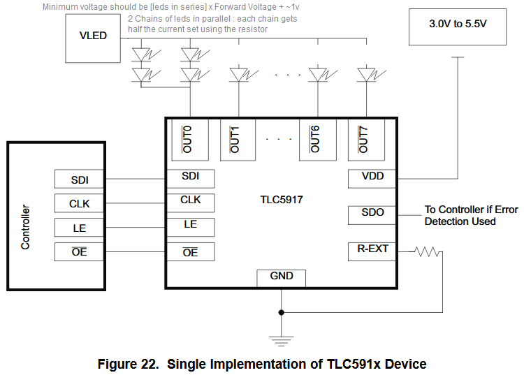
Let's say you have 4 blue leds that you want to drive with 50mA per LED... if you put them all in series, the total forward voltage would be 4x3.2v = 12.6v , which could be ABOVE the battery's voltage (which could be as low as 9v and as high as around 13.8v)
So, you can make two "chains" each with two leds in series, and then parallel them. The LED driver will "see" them as a LED with forward voltage of 2 x 3.2v = 6.4v and a current of 100mA ... the current will be more or less divided equally between the two chains and each chain gets 50mA
The VLED is the 12v from the battery... and it can be as little as 8v, as high as 20v ... the led driver will automatically control the current and only allow 100mA (or whatever current value you configure) to go through that channel.

You set the current limit on all channels to 100mA (or desired value) using that single Rext resistor (bottom corner of the image).

So besides this led driver chip, you only need a 3v ... 5v  from a linear regulator, which can also power a tiny 6+ pin microcontroller (an ATTiny, a PIC, whatever you want)... you only need 3 wires to interact with the led driver : SDI (data in), CLK (clock) and LE (latch enable).  The OE (output enable) can be permanently connected to ground if you don't need the functionality ("special mode", adjusting brightness of channels, see page 16, section 9.4 ).
So for example a 6pin microcontroller with built in oscillator would have input voltage pin, ground and 4 input or output pins... good enough.

« Last Edit: June 22, 2019, 09:41:38 am by mariush »
 

Offline andrewlaphamTopic starter

  • Contributor
  • Posts: 48
Re: Car battery confusion.
« Reply #17 on: June 22, 2019, 09:52:09 am »
I don't have any led driver IC's in my parts bin. I'm looking for a solution using mostly basic components. do you think i could get away with using a lm317 as my limiter? if so could someone provide a schematic for me to go on?

cheers
 

Offline Siwastaja

  • Super Contributor
  • ***
  • Posts: 8173
  • Country: fi
Re: Car battery confusion.
« Reply #18 on: June 22, 2019, 09:58:00 am »
LM317 datasheet should show an example circuit of a current limiter, look it up. Basically, it's a LM317 with a series resistor, but the ADJ pin connected so that the LM317 maintains constant 1.25V over this resistor, hence regulating current, not voltage. The resistor value is calculated to choose the exact current you want.

Then, you can connect as many LEDs in series as you have voltage margin to work with, which would be something like 12V - 1.25V and some margin, so 10V-ish. You should optimally use multiple LM317s, one for each chain, so that you won't need to parallel LEDs at all.

LM317 doesn't survive a full blown load dump, but should be quite OKish as long as you make sure it's not dissipating excessive heat at normal operating voltages (up to around 15V in a car).
« Last Edit: June 22, 2019, 09:59:54 am by Siwastaja »
 

Offline andrewlaphamTopic starter

  • Contributor
  • Posts: 48
Re: Car battery confusion.
« Reply #19 on: June 22, 2019, 10:15:38 am »
OK so if i use the lm317 and assume that my voltage source minimum is say 10v, i could feed a constant current of 20ma to each led providing that I'm around 2v higher than the load drop out voltage. that give me room for like 2 leds in series per lm317., right?
 

Offline mariush

  • Super Contributor
  • ***
  • Posts: 5029
  • Country: ro
  • .
Re: Car battery confusion.
« Reply #20 on: June 22, 2019, 11:09:37 am »
Yeah, but at this point wouldn't it be cheaper to just ORDER a bunch of led drivers from an online store and get them by next week?

Are you in that much of a rush to complete this project?

Seems like a waste to use one LM317 per 2 leds... not to mention they're not that accurate at low currents...

If you don't want to deal with microcontrollers, there's more basic led drivers/ current regulators like these for example: https://uk.farnell.com/w/c/led-lighting-components/led-driver-ics/led-drivers?no-of-outputs=1outputs&no-of-pins=2pins

NSI45020AT1G : https://uk.farnell.com/on-semiconductor/nsi45020at1g/ic-led-driver-45v-0-02a-sod123/dp/1794973

You put it in series with your leds and it limits the chain to 20mA +/- 20% ... simple as that.

Others available for various current amounts like 10mA (NSI50010YT1G) , 30mA (nsi45030at1g), 100mA (nsi45060jdt4g), and some have a 3rd pin you can use to limit current lower than preset value using a resistor.... NSI50150ADT4G for example with maximum 350mA current.
 

Offline Siwastaja

  • Super Contributor
  • ***
  • Posts: 8173
  • Country: fi
Re: Car battery confusion.
« Reply #21 on: June 22, 2019, 03:09:22 pm »
Yes, these two pin series constant current regulators are the greatest thing since sliced bread. They are like the series resistors, but actually regulate the current. If it all possible, just order some. One per LED chain.

"Voltage overhead" of 1.8V is fairly good if you compare it to a LM317-based constant-current regulator (2 + 1.2 = 3.2V), so you are probably able to put three LEDs per chain, and reduce power dissipation compared to a simple resistor which needs to drop more in order to regulate acceptably.


Share me

Digg  Facebook  SlashDot  Delicious  Technorati  Twitter  Google  Yahoo
Smf