Author Topic: Help requested understanding Make: Electronics 3rd Edition - Experiment 11  (Read 376 times)

0 Members and 1 Guest are viewing this topic.

Offline Tset_TsyungTopic starter

  • Newbie
  • Posts: 3
  • Country: gb
Hey all,

First post here.  Background is VR Development for training... but I had a breakdown end of 2024.  CFS has gotten bad and I still have a lot of anxiety problems.  I think I also had ADHD (undiagnosed).  I mention this so that y'all can hopefully understand why I'm hitting a cognitive brick wall with this.

So, I've decided to learn electronics as a hobbie and maybe a way back into self-employed work.  I have a basic Arduino kit (Elegoo 2560 mega), and a Humble Bundle that includes "Make: Electronics 3rd Edition" by Charles Platt.

All has been steady going (with some mentally grinding moments) until I hit Experiment 11 - the Astable Multivibrator!

[Please note: I'm including images and schematic txt files from falstad.com so that you can recreate it, if you'd like]

I have, after about a week of mulling it over, finally gotten my head around the 'why/how it works' of the basic flashing LED and the basic, single note, sound generator.  I haven't got all the right hardware, but am happy it works with Falstad.com and with help from Laurence Scotfords really helpful Youtube video.
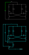

Falstad File

However, I then start losing the plot of what's going on.  As I continued with Laurence Scotfords video, I could see how connecting the circuits would change the sound... but I can't understand why. Furthermore, I feel that Charles Platt sort of 'hand waves' this instead of explaining what's actually happening - something I find infuriating as I need to understand on a more intuitive level, rather than with simple 'head knowledge'.


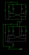
Second, combined setup file.

[Please Note: I can't seem to get reliable animations/readings from Falstad, else I would've persevered on my own for a bit longer]

My two main questions, at this point, are as follows:
1) Why (according to the video) does the second LED pulse much shorter, now that the circuits are connected and running together?
2) How, exactly, does the first circuit change the constant tone of the second circuit into a sort of climbing pitched squeak?

I have searched online but sort of hit more of a cognitive wall when I read other forum posts.

Any and all help would be greatly appreciated.  Thank you, all ;)

Mike
 

Offline Salome2

  • Regular Contributor
  • *
  • Posts: 74
  • Country: se
You are doing great in getting to understand circuits!  Watch the below links one after another to grow your  understanding.


Lots more stuff on youtube to help learn basic electronics!

Ans 1 and 2:  The frequency of the sound becomes higher or lower because the first multivibrator is changing the time it takes to charge the capacitor from its fixed set value (freq is only dependent of the charging resistor and cap until another circuit upsets the second multivibrator charging time)
The effect is that the second multivibrator frequency of oscillation is upset/modulated by the first multivibrator..
« Last Edit: January 19, 2026, 03:57:00 pm by Salome2 »
 
The following users thanked this post: Tset_Tsyung

Offline Tset_TsyungTopic starter

  • Newbie
  • Posts: 3
  • Country: gb
Hi Salome2,

Many thanks for the those links.  One of those is a video that I had already looked at.  As I mentioned, I understand how the Astable Multivibrator in standalone works.  My question was about the finer details of using one to modulate the other.  I couldn't find anything to help with that.

Regards,

Mike
 

Offline PGPG

  • Frequent Contributor
  • **
  • Posts: 973
  • Country: pl
My question was about the finer details of using one to modulate the other.
Frequency is determined by capacitors and resistors connected to transistor bases (not exactly resistors but rather supplied by them current that determines time needed to charge capacitor to switch its transistor on). If anything modifies anything there the frequency changes. Why it was done the way as at your pictures - I am surprised. I would be doing it different way. If for example you disconnect base resistors from supply and supply them (both) from the other source you will see that voltage you provide for these resistors modifies frequency, and I would influence this voltage by the other generator.
 
The following users thanked this post: Tset_Tsyung

Online iMo

  • Super Contributor
  • ***
  • Posts: 6413
  • Country: sm
Mr. Scotfords did his best in avoiding the explanation how the timing in the astable multivibrator actually works..  :D
It is not so easy and many many people have issues with it (it is critical to understand why you will get the rather large negative voltages at the bases as there the RC constant plays the role).
Below some sims you may look at (based on the video and your schematics).
When you are interested in electronics I would highly recommend you to download the LTspice simulator, it is free and easy to use.
Also creating videos which do show a populated breadboard and do not show a schematics (especially when targeting beginners) is wasting the time, imho..
« Last Edit: January 19, 2026, 06:17:39 pm by iMo »
Readers discretion is advised..
 
The following users thanked this post: Tset_Tsyung

Offline MariuszD

  • Frequent Contributor
  • **
  • Posts: 285
  • Country: pl
The charging voltage ramp of the capacitor is responsible for timing. The transistor circuit is an emitter follower that causes the ramp from one generator to shorten the ramp in the second generator.

 
The following users thanked this post: Tset_Tsyung

Online negativ3

  • Frequent Contributor
  • **
  • Posts: 259
  • Country: th
Mr. Scotfords did his best in avoiding the explanation how the timing in the astable multivibrator actually works..  :D
It is not so easy and many many people have issues with it (it is critical to understand why you will get the rather large negative voltages at the bases as there the RC constant plays the role).
Below some sims you may look at (based on the video and your schematics).
When you are interested in electronics I would highly recommend you to download the LTspice simulator, it is free and easy to use.
Also creating videos which do show a populated breadboard and do not show a schematics (especially when targeting beginners) is wasting the time, imho..

Second the recommendation to dip your toe into LTSpice. It is quite a steep learning curve and if any components are missing, you can usually find models online. Practice and you'll soon cross the wall of understanding to implementation.
 
The following users thanked this post: Tset_Tsyung

Offline Tset_TsyungTopic starter

  • Newbie
  • Posts: 3
  • Country: gb
Thank you all of you for your help.

I've downloaded LTSpice, and am working through some tutorials (including importing a 2N3904 transistor model).  This will take some time to get my exhausted head around it, but love it already.

Many thanks, as well, regarding the pointer about how the charge affects the timing of the other - this will definitely be where I focus my LTSpice investigations.

Again, many thanks.  I'll update when I've hit that 'eureka' type moment. ;)

Regards,

Mike


Share me

Digg  Facebook  SlashDot  Delicious  Technorati  Twitter  Google  Yahoo
Smf