I actually can't see that blown resistor, as much as I try.
Yes, it's probably not 12v if the capacitors are rated for 50v. is there some text around the connector on the amplifier board that could tell you if it's +V and -V, or that could tell you the voltages?
If you want to continue and try to fix that, I would suggest replacing the fuse and the two 13009 and the resistor (but i don't see it) and see if that solves it. (if you want, you can put a incandescent lightbulb in series with the mains as a current limit, to protect
Those TO-220 ICs on the heatsink what does it say on them? If they say something like MBR20100... those numbers tell you it's a diode rated for maximum 20A , 100v - that could tell you voltage is below 100v (usually much lower) and the power supply outputs less than 20A - doesn't get you much closer to figuring the output voltage but it's something.
It would be somewhat useful to figure out the wattage of the power supply, but you can also do this by looking at the label in the back of the speaker where it says 220v 0.5A or something like that - that would mean 100w power supply (220*0.5a = 110w), or you could look at the specs of the speaker on the website and if it says maximum 75w or something like that you should estimate a 100w psu due to the amplifier efficiency.
Are the wires colored differently in the cable going to amplifier board? That's a hint (but not always, not reliable) that you have -v and +v.
Can you see on the amplifier board what amplifier chip is used? Post some pictures of the boards and write down what it says on the ICs on that amplifier board. Some ICs have datasheets available, so you can figure out the maximum input voltage of that amplifier chip and determine the power supply from there. Some datasheets even have basic circuit examples showing how the chip is connected with single power supply or with -v and +v so you may get a clue from there about what power the amplifier board expects.
edit: ah I see you pm'ed with TDA8920 : that needs at least +/- 12.5v , typically +/-27v, maxim +/- 30v. The power supply probably outputs +/- 24v.
I'm not sure where you'll find a power supply with positive and negative voltages cheaply. Maybe you can find one with two separate 24v outputs or get 2 24v power supplies and connect the + of one to - of one and get your virtual ground that way.
Alternatively, you can get a 36v transformer with center tap rated for about 100VA or more and build one :
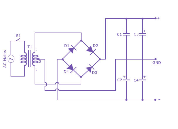
You'd need quite a bit of capacitance on each +v and -v, that's why there's 2 caps on each side. I would go with at least 10.000 uF on each side, so maybe 1 x10000uF 35/50v or 2 x 8200uF 35v or 50v on each side.
Something like this would work:
http://uk.farnell.com/pro-power/ctfcs100-18u/transformer-100va-2-x-18v/dp/1780897 (not sure where you are, you don't say the country)
If you go this route, make sure you connect -v and +v where they should be... you can follow the traces on the amplifier board to the power connector to see where -v and +v go. Or just put your multimeter in continuity mode, put a probe on the tda chip on the pin for POSITIVE power supply and then on the pins of that connector, and you figure out the positive pin. Same for negative and ground. The pins for tda chip are in the datasheet.
And you'd also need that 5v which you can probably get from a basic wallwart or phone charger.


