I've been investigating Vackar oscillators on my workbench and in my spice sims (QUCS and Micro-Cap). Take for example this triode powered oscillator from figure 5 of
Vackar's 1949 paper:
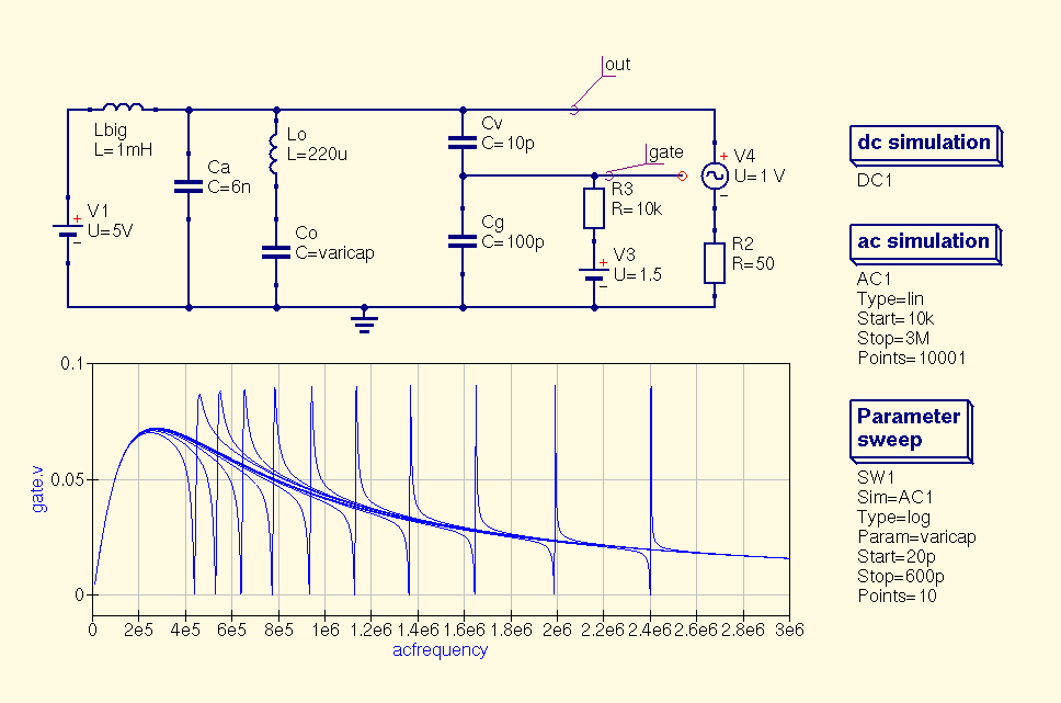
My initial buildup looks approximately like this:

I promise the diagrams are identical, I've just re-arranged things and added a (slightly off) bias voltage for my mosfet.
Previously I used transient analysis in my SPICE sim to see how oscillators behaved, but this was fiddly and time consuming. I realised I could probably get most of the information I needed by running an AC simulation instead.
Method 1: Substituting the mosfet- Replace the transistor with a sine voltage source (ie Vds = input to control, Vgs = output to measure)
- Look for a peak in my gate voltage versus frequency graph indicating where the circuit resonates (and therefore may oscillate)
- Sweep the values of my variable capacitor so I can see different target oscillation frequencies (peaks in my graph).
 Question:
 is this analysis technique valid, or am I making some bad assumptions here?
Method 2: Adding an AC signal in series with the transistorI thought keeping the transistor itself in the loop would make more sense, ie analyse the oscillator as a whole (not just as a network of RLC). (EDIT:) It seems to resonate much more sharply, floor at 0V and has an odd resonating point low down, making me think I'm doing something silly:

Playing with the MOSFET bias doesn't seem to improve this, only make it worse.


