Author Topic: Is this function generator broken?  (Read 7240 times)

0 Members and 1 Guest are viewing this topic.

Offline injbTopic starter

  • Regular Contributor
  • *
  • Posts: 64
Is this function generator broken?
« on: November 26, 2014, 03:37:59 am »
Hi, I'm completely new here. I'm trying to figure out if there is something wrong with this Kenwood FG 273 function generator I just bought on eBay, or if I am just an idiot :) I'd really appreciate any feedback (either way!)

First let me say, I am very inexperienced with this stuff - I have tinkered a little with electronics before, but this is the first time I've used a function generator, and I'm using it to help me get the hang of my new oscilloscope, which is also the first oscilloscope I've used. It's a digital scope that uses an Android phone (http://www.osciprime.com/).

Secondly, sorry for making such a long pic-heavy first post. But it's the only way I can describe the problem I'm having.

Anyway, I am pretty sure the scope is working fine. I've used it to look at some signals on my car and I have found no issues with it. But the waveforms I see from my new (to me) function generator make no sense to me. The problems are:

1. unbelievably low amplitude. There is simply no way I can see anything unless I (a) switch my probe from x10 to x1, *and* (b) turn up my scope's gain to the max. If I turn up the amplitude much on the function generator, the signal clips (it's not my scope that's clipping).

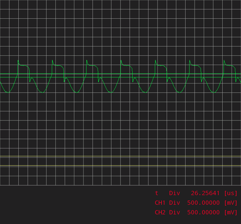
2. strange distortion on sine and triangular waves, that gets worse with frequency.

3. the amplitude control does strange things to the wave shapes at anything above a few Khz.

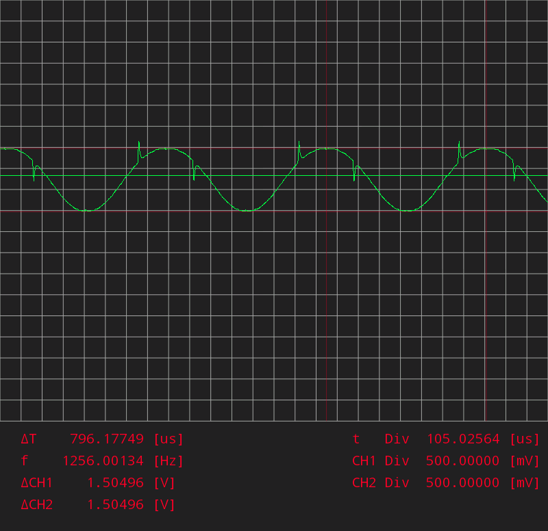
To help get some feedback on this, I've taken some screenshots. This first one illustrates problems 1 and 2. Bear in mind, the scope is assuming the probe is x10, so the actual voltage of the signal here is one thenth, i.e. about 150mv peak to peak. I don't really have a sense of how much a function generator *should* output, but surely it should be more than that? I was expecting something more like 1v?


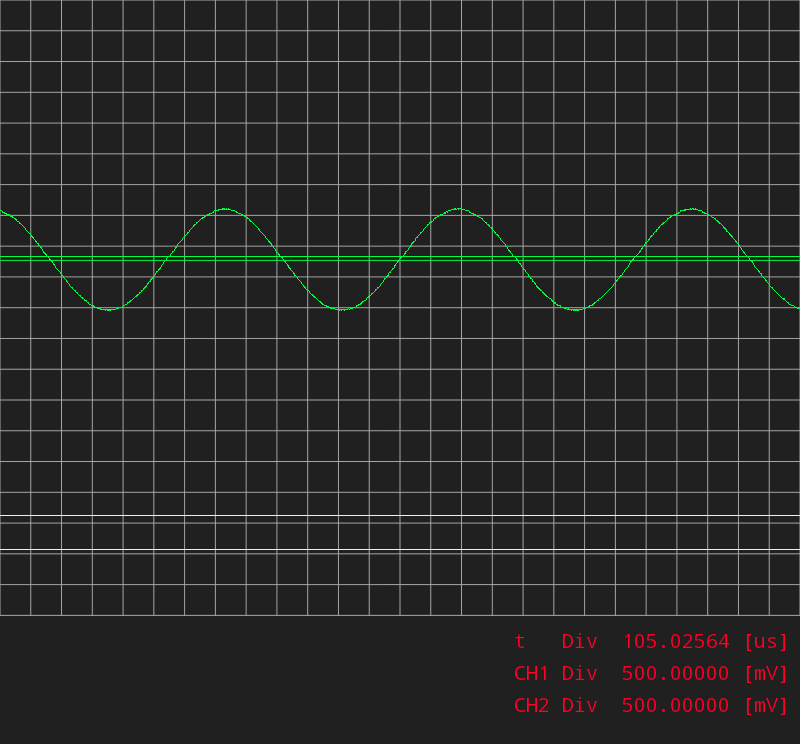
Now, here's a signal of the exact same frequency coming directly from my laptop's soundcard (http://onlinetonegenerator.com/) - so you can see it's not the scope or the probe that's causing the spikes:


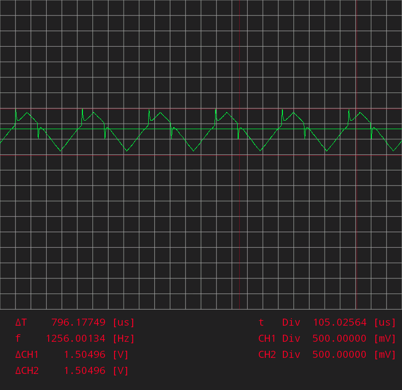
Here's the triangular wave from the function generator - exactly the same issue:


Regarding the amplitude, here's what happens when I try turning that up (remember my probe is on x1 here, but the voltage display assumes x10):


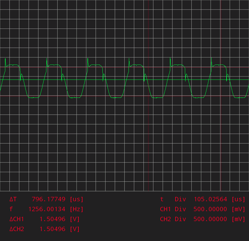
And here's what happens when I turn up the frequency - this is at around 10khz (my scope samples at 6ms/s and is supposed to have an analog bandwith of at least 3.3mhz with the gain setting I"m using here, so this should be no big deal):


If you got this far, thanks for reading! And can you shed any light on this? Should I send this function generator back as defective? Or am I missing something? I think I have a reasonable understanding of pretty much all the controls, and I can't seem to fix any of my problems with any of them. But maybe I am missing something fundamental...


« Last Edit: November 26, 2014, 03:41:14 am by injb »
 

Offline edavid

  • Super Contributor
  • ***
  • Posts: 3383
  • Country: us
Re: Is this function generator broken?
« Reply #1 on: November 26, 2014, 05:10:35 am »
Sure looks broken!
 

Offline marshallh

  • Supporter
  • ****
  • Posts: 1462
  • Country: us
    • retroactive
Re: Is this function generator broken?
« Reply #2 on: November 26, 2014, 05:47:20 am »
Yup, definitely needs some attention.
Verilog tips
BGA soldering intro

11:37 <@ktemkin> c4757p: marshall has transcended communications media
11:37 <@ktemkin> He speaks protocols directly.
 

Offline Paul Price

  • Super Contributor
  • ***
  • Posts: 1419
Re: Is this function generator broken?
« Reply #3 on: November 26, 2014, 09:55:52 am »
NFG

Check the battery.
 

Offline injbTopic starter

  • Regular Contributor
  • *
  • Posts: 64
Re: Is this function generator broken?
« Reply #4 on: November 26, 2014, 01:51:11 pm »
Thanks for chiming in everyone.

It's powered by the mains so no battery. I'll contact the seller and start shopping for another one.
 

Offline injbTopic starter

  • Regular Contributor
  • *
  • Posts: 64
Re: Is this function generator broken?
« Reply #5 on: November 27, 2014, 06:28:41 pm »
Well as I suspected might happen, the seller offered to let me keep it with a partial refund. I was thinking about trying to fix it myself. They're not currently offering enough to make it worthwhile, but I think they might.

My reasoning is that since the basic waveforms are there, but distorted, and the distortion gets worse when I try to turn up the amplitude, and the amplitude is way too low over all...I'm guessing that the problem is with the final amplifier stage, and I might be able to identify the bad component easily enough. I don't have a schematic for it though. Any suggestions? Is it likely to be a difficult thing to track down and fix without schematics?  Thanks!
 

Offline edavid

  • Super Contributor
  • ***
  • Posts: 3383
  • Country: us
Re: Is this function generator broken?
« Reply #6 on: November 27, 2014, 06:42:34 pm »
Usually it's just one or more transistors in the output stage, but there could be some other bad parts.

Looks like you can buy the schematic here for $5: http://www.manualscenter.com/manuals/kenwood/fg273-service-manual.html
 

Online Zero999

  • Super Contributor
  • ***
  • Posts: 19514
  • Country: gb
  • 0999
Re: Is this function generator broken?
« Reply #7 on: November 27, 2014, 07:11:27 pm »
Did you buy it from a commercial seller? Are they in the same country?

Was it advertised as used or new?

I say sod them. Don't spend any money or time on this. Send it back and get a full refund. If they won't do that, file a complaint with ebay, especially if it's a commercial seller and it was advertised as new.
 

Offline injbTopic starter

  • Regular Contributor
  • *
  • Posts: 64
Re: Is this function generator broken?
« Reply #8 on: November 27, 2014, 07:26:52 pm »
edavid thanks for the link.

It was advertised as used and working. I don't think there's any question of hassle from the seller. I've requested a return via eBay and they always allow the buyer and seller to discuss things amicably before stepping in. So I can still insist on a full refund including my shipping costs, and send it back at their expense - I don't think they'll argue. The seller is just trying to save themselves having to refund me and pay the shipping to have a useless item return to them. My guess is they will junk it if I send it back. So I think their offer is ok in principle....I was thinking of counter offering - full price refund, less what I paid for shipping. That way, I'll have a function generator that I might be able to fix for about $17 (what I paid for shipping) plus a few parts,  and they'll save $34 (the cost of shipping both ways which they would otherwise have to pay).


Offline injbTopic starter

  • Regular Contributor
  • *
  • Posts: 64
Re: Is this function generator broken?
« Reply #9 on: December 02, 2014, 03:03:48 pm »
Well the seller and I agreed that I would keep it and get a refund less shipping. So I have effectively paid $17 for it. I opened it up to take a look.

I immediately found a clean, distortion free signal with up to 2v peak to peak, at the wires going to and from the amplitude pot (yellow circle in the pic). From there I traced it to what looks like the final amplifier stage - there are 2 connectors next to 2 can shaped transistors with big heat sinks on them (red circle). One of those connectors has the good signal, the other one has the bad one and goes to the BNC connector. So it does look like it's that final stage where the problem is, and at least I know the signal generation is definitely working.


I still need to trace it more closely and make sure, but I'm pretty sure those transistors are the problem. At least one of them is a 2N2219A which still seems to be available. Are the heat sinks easy to salvage or should I be looking for new ones?
 

Offline Andy Watson

  • Super Contributor
  • ***
  • Posts: 2084
Re: Is this function generator broken?
« Reply #10 on: December 02, 2014, 03:16:37 pm »
The heatsinks are simply "sprung" loaded to clamp on to the transistor. Use a screw driver blade as a wedge and insert it into the split just sufficiently to ease the clamping pressure.
 

Offline timb

  • Super Contributor
  • ***
  • Posts: 2536
  • Country: us
  • Pretentiously Posting Polysyllabic Prose
    • timb.us
Re: Is this function generator broken?
« Reply #11 on: December 02, 2014, 03:17:36 pm »
Heat sinks will pop right off. 2n2219's are pretty much the most common NPN transistor in the world,  the only trouble you'll have is finding them in those metal cans in current production. That said, you should have no trouble buying NOS (New Old Stock) off eBay. I always keep a few dozen on hand for fixing old gear.


Sent from my Tablet
Any sufficiently advanced technology is indistinguishable from magic; e.g., Cheez Whiz, Hot Dogs and RF.
 

Offline jlmoon

  • Supporter
  • ****
  • Posts: 609
  • Country: us
  • If you fail the first time, keep trying!
Re: Is this function generator broken?
« Reply #12 on: December 02, 2014, 06:56:44 pm »
Well the seller and I agreed that I would keep it and get a refund less shipping. So I have effectively paid $17 for it. I opened it up to take a look.

I immediately found a clean, distortion free signal with up to 2v peak to peak, at the wires going to and from the amplitude pot (yellow circle in the pic). From there I traced it to what looks like the final amplifier stage - there are 2 connectors next to 2 can shaped transistors with big heat sinks on them (red circle). One of those connectors has the good signal, the other one has the bad one and goes to the BNC connector. So it does look like it's that final stage where the problem is, and at least I know the signal generation is definitely working.


I still need to trace it more closely and make sure, but I'm pretty sure those transistors are the problem. At least one of them is a 2N2219A which still seems to be available. Are the heat sinks easy to salvage or should I be looking for new ones?


Do I see R102 (1Watt resistor) looking a little crusty?
-- or is that just my imagination?
 :-//
Recharged Volt-Nut
 

Offline jlmoon

  • Supporter
  • ****
  • Posts: 609
  • Country: us
  • If you fail the first time, keep trying!
Re: Is this function generator broken?
« Reply #13 on: December 02, 2014, 07:04:54 pm »
I am also guessing that R102 & R103 power resistors are the current limiting for the output stages.  I would venture to guess you will have a + & a - potential on those in reference to ground.. one end of those resistors are probably tied to the Collectors of those two output transistors that have the round heatsinks wrapped around them.  good place to start looking for trouble.  Those two moderately sized electrolytic s are a start as well.
 
Recharged Volt-Nut
 

Offline injbTopic starter

  • Regular Contributor
  • *
  • Posts: 64
Re: Is this function generator broken?
« Reply #14 on: December 02, 2014, 07:08:04 pm »
Cool thanks for the tips! That resistor does look a little funky in that pic but it's not a great pic, so I'll take a look later.
 

Offline Anks

  • Frequent Contributor
  • **
  • Posts: 252
  • Country: gb
    • www.krisanks.wordpress.com
Re: Is this function generator broken?
« Reply #15 on: December 02, 2014, 07:24:15 pm »
To me this looks to be an issue with only one side of the waveform and if that is the case then I would say the problem is only on one side of the output stage. Have you measured the voltages at the two big resistors to see if the voltage is balanced as it looks to be a issue with crossover point of a push pull output stage. Also check those big caps as one could of gone bad so maybe check there ESR or scope the rails for ripple
« Last Edit: December 02, 2014, 07:25:54 pm by Anks »
 

Offline jlmoon

  • Supporter
  • ****
  • Posts: 609
  • Country: us
  • If you fail the first time, keep trying!
Re: Is this function generator broken?
« Reply #16 on: December 02, 2014, 09:42:08 pm »
You might look at the signals around that differential amp pair that are bonded together near slightly to the right of  the connector on the left of pic.. (Red,Orange,Green wired 3pin).   Could be an issue with bias or current mirror offset creating a cutoff condition down the output section. 
Recharged Volt-Nut


Share me

Digg  Facebook  SlashDot  Delicious  Technorati  Twitter  Google  Yahoo
Smf