Author Topic: Measuring current of two shunts in serries  (Read 3467 times)

0 Members and 1 Guest are viewing this topic.

Offline Red SquirrelTopic starter

  • Super Contributor
  • ***
  • Posts: 2750
  • Country: ca
Measuring current of two shunts in serries
« on: June 02, 2016, 04:28:28 am »
Say you have two shunts in series, one is before a power converter and the other one is after, what is the best way to measure the current?  As one is going to effect the other.  Here is a sample circuit:


Basically let's say it's a 24vdc to 12vdc converter with a 2 amp load at the end, idealy  (let's assume 100% efficiency) I'd measure 2 amps on the second shunt, and 4 amps at the first, as it would be at a lower voltage.  But the second shunt's voltage is already going to be lower relative to ground because of the first shunt, so that alone is going to mess up the reading I think. 

What is the best way to deal with something like this?  Will the difference be linear, can I just deduct the value of the first shunt in software to get the proper reading for the second one? 
 

Offline jeroen79

  • Frequent Contributor
  • **
  • Posts: 529
Re: Measuring current of two shunts in serries
« Reply #1 on: June 02, 2016, 05:53:01 am »
Why are you putting the shunts in series?
Right now R5 will carry the current for both load R9 and the load on the right while R12 will carry the current of only the load on the right.

Deducting the output of U1 from the output of U3 would give the voltage drop over R12.
And deducting the current through R12 from the current through R5 would give the current through load R9.

But if you put the shunts and loads in parallel you could measure both independantly.

Code: [Select]
(+)---+------+
      |      |
    Load1  Load2
      |      |
     R5     R12
      |      |
(-)---+------+
 

Offline Red SquirrelTopic starter

  • Super Contributor
  • ***
  • Posts: 2750
  • Country: ca
Re: Measuring current of two shunts in serries
« Reply #2 on: June 02, 2016, 07:04:43 am »
Basically I need to be able to measure the amps going in and amps going out as well as the voltage (will just use a voltage divider for that).  It will be a crude MPPT controller so I need to know the current at the solar panel and I also want to know the current after, just for informational purposes.

So is it as simple as deducting the value I get for the other shunt or will it get more complicated that that with the actual system voltage also changing?   Though on second thought, I might be able to skip having the second shunt right there, and have the ground and positive go straight to the battery, then another positive and negative from the battery to the load, and I can put the shunt on that negative to measure load.  Though I think I'll still be in the same boat as technically the battery negative won't be 100% the same as the solar panel negative.  Which come to think of it might be an issue for voltage measuring as well...  though it will be a rather small amount of difference so probably negligible.
 

Offline Rerouter

  • Super Contributor
  • ***
  • Posts: 4694
  • Country: au
  • Question Everything... Except This Statement
Re: Measuring current of two shunts in serries
« Reply #3 on: June 02, 2016, 07:12:02 am »
as your voltages are low, just measure deferentially across both shunts,

https://upload.wikimedia.org/wikipedia/commons/thumb/a/a2/Op-Amp_Differential_Amplifier.svg/300px-Op-Amp_Differential_Amplifier.svg.png

Or

http://www.circuitdiagramworld.com/amplifier_circuit_diagram/Two_Op_Amps_Instrumentation_Amplifier_17538.html

For the second style you can easily divide down the input voltages into a range your comfortable with,
 

Offline Red SquirrelTopic starter

  • Super Contributor
  • ***
  • Posts: 2750
  • Country: ca
Re: Measuring current of two shunts in serries
« Reply #4 on: June 02, 2016, 08:17:27 pm »
Made a change to the circuit, the other one was more of a quick prototype I was playing with on the bench but it's not quite what I need so made one closer to the real thing:


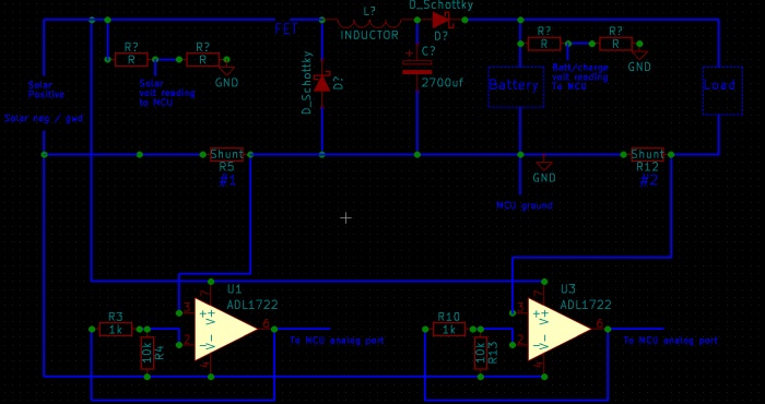
Basically the first shunt will measure the current coming from the solar panel going to the buck converter, which will charge the battery. 

The second shunt will measure the current of the load from the battery (and naturally from solar panel too if it's producing).

Problem with this circuit is that the solar panel ground is going to be more negative than the system ground, I think.  The MCU will be powered by the battery so it's ground will be the battery ground and everything else will be referenced by that. 

What about high side current sensing, would that be easier in this case?  Though that requires the op amp to be able to handle the highest voltage of the system right?  And this voltage is going to change all the time so it would be a challenge to power the op amp with the proper voltage even if it can handle it. I originally wanted to use hall effect sensors but they don't seem to make many that are through hole and I'm not equipped at all to do SMD.  I tried.  I have some 30 amp sensors and they're just too small to do without a proper PCB and a microscope.

Worse case scenario I can get rid of the load current sensing, it's just a nice feature I wanted to have so that I know how much I'm drawing from the system, but the first shunt is the most important as it will be used for basic MPPT purposes.

Would current transformers work for DC?  I think those are only for AC right?


Also just realized I kinda messed up, my op amps won't be powered by the solar panel as shown, but by a voltage regulator that is powered by the battery.  That same voltage regulator will power the MCU.  I have a more detailed circuit but it's a mess so that's why I had made that one just to show the important parts.
« Last Edit: June 02, 2016, 08:25:13 pm by Red Squirrel »
 

Offline Rerouter

  • Super Contributor
  • ***
  • Posts: 4694
  • Country: au
  • Question Everything... Except This Statement
Re: Measuring current of two shunts in serries
« Reply #5 on: June 02, 2016, 08:24:27 pm »
To compensate for the grounding, move the grounded end of your 10K resistor (op amp divider) to the other end of the shunt its measuring, this will compensate for changes in ground voltage.
 

Offline Red SquirrelTopic starter

  • Super Contributor
  • ***
  • Posts: 2750
  • Country: ca
Re: Measuring current of two shunts in serries
« Reply #6 on: June 02, 2016, 09:05:48 pm »
Oh right that makes sense.  I should probably do it for both for good measure. 
 

Offline HackedFridgeMagnet

  • Super Contributor
  • ***
  • Posts: 2028
  • Country: au
Re: Measuring current of two shunts in serries
« Reply #7 on: June 02, 2016, 11:34:29 pm »
Oh right that makes sense.  I should probably do it for both for good measure

Spotted, double double entendre. Nice work.
 

Offline Red SquirrelTopic starter

  • Super Contributor
  • ***
  • Posts: 2750
  • Country: ca
Re: Measuring current of two shunts in serries
« Reply #8 on: June 02, 2016, 11:54:24 pm »
I totally did not even intend that.   :-DD
 

Offline Red SquirrelTopic starter

  • Super Contributor
  • ***
  • Posts: 2750
  • Country: ca
Re: Measuring current of two shunts in serries
« Reply #9 on: June 06, 2016, 02:45:59 am »
I'm thinking I"m going to rethink how I measure my current points as I really don't like the idea that it's disturbing the ground, I think that will cause issues with the MCU and all the other readings.  Also I can't seem to figure out how to get non noisy readings on shunts.  It looks terrible on the scope, ex:


I could do some kind of averaging at the micro but with this much noise I don't think it will do much, especially since this will need to do some rather fast readings for SMPS reasons (it will be a buck converter) so it's not like I can take 100 readings and average them out then decide if the mosfet goes on or off.

Think I might bite the bullet and buy a purpose built IC, think this would work?
http://www.digikey.ca/product-detail/en/allegro-microsystems-llc/ACS770LCB-50U-PFF-T/620-1542-5-ND/4473981
Kinda pricy though.  It's the only through hole ones I can find.  They have some higher amp ones too but 50a is way more than I need.  I only need to read up to maybe 20 amps.  System will be rated for 10 but good idea to be able to read more.

Also this would not disturb the ground as it appears it can be used high side.  I could technically use shunts high side though, but I'd need to buy different op amps, some that can handle those voltages.  Open to other suggestions as well. What about current transformers, can those work with DC?  I always had the impression no, but I do have a clamp meter that reads DC.  I think if I stick to anything that can do high side reading then that will be better.  At least everything that is grounded is all going to be the same throughout the circuit so all voltage readings will be at same potential, if that makes sense.

Edit: Upon further investigation think the issue with noise may be my scope... going to make a separate thread.
« Last Edit: June 06, 2016, 03:56:21 am by Red Squirrel »
 

Offline Rerouter

  • Super Contributor
  • ***
  • Posts: 4694
  • Country: au
  • Question Everything... Except This Statement
Re: Measuring current of two shunts in serries
« Reply #10 on: June 06, 2016, 08:36:41 am »
Ok, found another issue, your MCU and your op amps do not share a ground reference,

Move there ground to the battery ground aswell, and wire up the op amps like shown,

On the left side one, while the op amp is powered no pins will ever see a negative voltage

And yeah i just pulled the values out of my backside,
 

Offline Red SquirrelTopic starter

  • Super Contributor
  • ***
  • Posts: 2750
  • Country: ca
Re: Measuring current of two shunts in serries
« Reply #11 on: June 06, 2016, 03:52:42 pm »
Yeah I messed up that diagram, the op amp is actually going to be powered by the same ground and 5v as the micro.   That actual circuit is going to be 12v+ (more on the solar side) so my diagram would lead to magic smoke.  :P

This is what I have so far, some resistor values may change based on experiments.  I'm still waiting for a roll of nichrome wire to come in so I can build myself a basic test load as I don't have much to test with right now but some 12v LED bulbs and inverter. 

« Last Edit: June 06, 2016, 03:59:15 pm by Red Squirrel »
 

Offline Rerouter

  • Super Contributor
  • ***
  • Posts: 4694
  • Country: au
  • Question Everything... Except This Statement
Re: Measuring current of two shunts in serries
« Reply #12 on: June 06, 2016, 08:25:57 pm »
your load shunt is back to front,
 

Offline Red SquirrelTopic starter

  • Super Contributor
  • ***
  • Posts: 2750
  • Country: ca
Re: Measuring current of two shunts in serries
« Reply #13 on: June 06, 2016, 11:47:55 pm »
Oh right it is, I swapped those.


Share me

Digg  Facebook  SlashDot  Delicious  Technorati  Twitter  Google  Yahoo
Smf