Author Topic: Where does my car stereo get -5V from?  (Read 4437 times)

0 Members and 1 Guest are viewing this topic.

Offline DijitalTopic starter

  • Contributor
  • Posts: 18
  • Country: us
Where does my car stereo get -5V from?
« on: July 07, 2017, 12:31:07 am »
I've started work on an  equalizer for the subwoofer pre-outs on my car's headunit. Basically, headunit-> my eq circuit -> sub amp. I'd like to have full band boost/cut, as well as some frequency specific boosting/cutting. But that's besides my question.

Today I was characterizing the sub output signals from the headunit with a 50Hz sine and found that the voltage swung from +5 to -5V, relative to the cars chassis ground. I don't know what I was expecting, I guess i just didn't think about it much, but where is the negative voltage coming from? I mean everything is powered from the +12V battery. I'm not sure how to go about making my circuit now since I would need a negative rail for the op amps. Would I  need to implement dc-dc converter to create a negative rail? Maybe just a charge pump will do? Is there some trick to this that I am missing?
« Last Edit: July 07, 2017, 12:35:28 am by Dijital »
 

Offline Richard Crowley

  • Super Contributor
  • ***
  • Posts: 4319
  • Country: us
  • KJ7YLK
Re: Where does my car stereo get -5V from?
« Reply #1 on: July 07, 2017, 12:39:03 am »
1) You could simply be looking at an AC-coupled signal through an output capacitor. That makes all signals appear to be centered around 0 volts (ground).
2) Your gadget could have a DC-DC converter internally which creates negative and/or other positive voltages from the vehicle 13.6V
 

Offline DijitalTopic starter

  • Contributor
  • Posts: 18
  • Country: us
Re: Where does my car stereo get -5V from?
« Reply #2 on: July 07, 2017, 01:47:09 am »
1) You could simply be looking at an AC-coupled signal through an output capacitor. That makes all signals appear to be centered around 0 volts (ground).
2) Your gadget could have a DC-DC converter internally which creates negative and/or other positive voltages from the vehicle 13.6V

So could I just use a voltage divider to shift the voltage at the eq input and then use a cap at the output?
 

Offline timb

  • Super Contributor
  • ***
  • Posts: 2536
  • Country: us
  • Pretentiously Posting Polysyllabic Prose
    • timb.us
Re: Where does my car stereo get -5V from?
« Reply #3 on: July 07, 2017, 02:49:13 am »
1) You could simply be looking at an AC-coupled signal through an output capacitor. That makes all signals appear to be centered around 0 volts (ground).
2) Your gadget could have a DC-DC converter internally which creates negative and/or other positive voltages from the vehicle 13.6V

So could I just use a voltage divider to shift the voltage at the eq input and then use a cap at the output?

Yup. The value of the output cap will be a function of the lowest frequency of the signal you want to pass and the impedance of what you're outputting into. Remember, the cap is AC coupling the signal, so if you were trying to pass a 10Hz signal through a 1uF cap into an 8Ohm speaker, it wouldn't work. The signal would get cut off at 20KHz or so.

It essentially acts as a high pass filter. This is why the coupling caps on audio amplifiers are large values (several hundred uF). Now, since this is an EQ, I assume the signal will be going into an amp and not directly into speakers, correct? Assuming a worst case input impedance of the amplifier as 1kOhms and you want a minimum 20Hz response, you should be OK with a 10uF cap on the output of your EQ. :)

If those values aren't correct you can do the math yourself: C = 1/(2*Pi*Fg*R) where Fg is the frequency and R is the input impedance.
Any sufficiently advanced technology is indistinguishable from magic; e.g., Cheez Whiz, Hot Dogs and RF.
 

Offline Richard Crowley

  • Super Contributor
  • ***
  • Posts: 4319
  • Country: us
  • KJ7YLK
Re: Where does my car stereo get -5V from?
« Reply #4 on: July 07, 2017, 05:04:18 am »
So could I just use a voltage divider to shift the voltage at the eq input and then use a cap at the output?
No. You don't need to shift the audio signal.   It has already been shifted for you with the capacitive coupling from the headunit.

Two popular options:
1) Create an artifical, "virtual" ground which is exactly halfway between 0V ground and the vehicle battery voltage (12V "nominal", but up to perhaps 14-15V). This circuit will take whatever vehicle battery voltage you have and divide it exactly in half. 


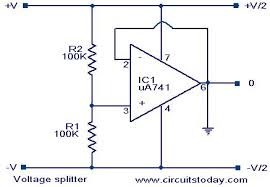
You can call that halfway voltage "ground" INSIDE your EQ circuit.  As long as the INPUT is capacitively coupled (which is always a good idea in any case) and the output is capacitively coupled (also always a good idea in a car circuit), the circuit INSIDE your EQ will be quite happy operating on what appears to be +6V and -6V (relative to the internal virtual ground).  There are hundreds of circuits that show how this was done in commercial products.  You can learn a lot from reading other people's schematic diagrams.

2) If you think you need more than +/- 6V, then use a DC-to-DC converter.  There are literally dozens (or scores or even hundreds) of these things for sale on Ebay an other places.  Most are so dirt-cheap that it will probably cost more to ship than it costs.

Some examples:
http://www.ebay.com/itm//282513241853


There are dozens of these:
http://www.ebay.com/itm/262752631334


http://www.ebay.com/itm/311419151111


And many many more like these....
It is hardly worth DIY when you can get these things so cheap.
They are IDEAL for vehicle circuits.
They all accept a wide range of input voltages with 12V well within the design range.
And they put out balanced DC voltages designed to operate audio circuits using op-amps.
Exactly like your EQ circuit.
« Last Edit: July 07, 2017, 05:06:55 am by Richard Crowley »


Share me

Digg  Facebook  SlashDot  Delicious  Technorati  Twitter  Google  Yahoo
Smf