Author Topic: Schematic design - a beginner's journey  (Read 6194 times)

0 Members and 1 Guest are viewing this topic.

Offline CanobiTopic starter

  • Regular Contributor
  • *
  • Posts: 94
  • Country: gb
Schematic design - a beginner's journey
« on: October 14, 2015, 12:07:16 pm »
Hey guys


I've never made a complex schematic before as many aspects of electronics eluding me for many years due to dyslexia but have alway had a passion for it regardless. For much of my life I've learned by doing and observing and have a few skills that are eager for the rest of me to catch up.

My latest project is a holy grail of mine and this time I'm going to see if I can do things properly as I need some some pointers in other areas of my project and having a schematic I can show would probably go a long way in getting said pointers.

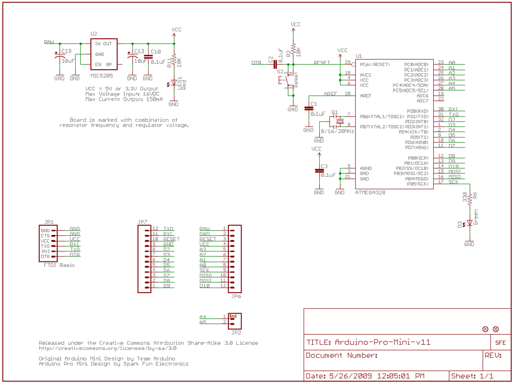
It's actually not the level of complexity that's an issue, its not knowing certain factors, one such is why parts of the same circuit are sometimes represented as seperate islands that appear not to be connected.

Since I'm trying to include an arduino pro mini in my drawing, I'll put the schematic for it here as its also a good representation of the islands I was reffering to:


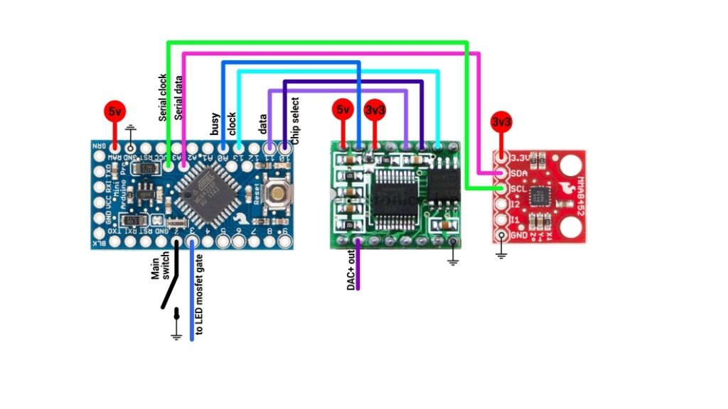
This is a diagram of the circuit I'm trying to represent in my schematic which consists of the pro mini, WT588D-16p audio playback module and MMA8452Q accelerometer breakout (yes, its for a lightsaber):


What I do know about schematic design is that positive should be at the top, negative at the bottom and connections from left to right.

The things that are bugging me most are:

As I'm using modules in real life, do I need to include all their parts in the final schematic or can I just concentrate on the functions/pins/connections I'm using and assume the others exist?


Since the modules are already pre designed circuits in their own right, could I do this simply by placing all three schematics together (but not too close abviously) and just show which of the other pins are connected between them.

That could just be me inventing an unacceptable work around though so any help would be most appreciated.
 

Offline tggzzz

  • Super Contributor
  • ***
  • Posts: 19672
  • Country: gb
  • Numbers, not adjectives
    • Having fun doing more, with less
Re: Schematic design - a beginner's journey
« Reply #1 on: October 14, 2015, 01:23:14 pm »
It's actually not the level of complexity that's an issue, its not knowing certain factors, one such is why parts of the same circuit are sometimes represented as seperate islands that appear not to be connected.

The purpose of a schematic is (1) to provide a netlist for a PCB layout program and (2) help the designer and maintainer understand how and why the circuit operates.

It is reasonable to have a few "unconnected" islands, e.g. for decoupling capacitors and the PSU.

Otherwise having unconnected islands is a recent trait that greatly reduces the ability for a reader to comprehend a circuit - it is a lazy habit that should be deprecated. A simple example: consider having a R/W (read/write) signal generated by a processor, which can be expected to go to most i/o circuits. If someone is looking at a schematic (especially an image) to debug a circuit, how can they be sure that they have spotted all connections to that signal - unless they are all explicitly connected.

Quote
As I'm using modules in real life, do I need to include all their parts in the final schematic or can I just concentrate on the functions/pins/connections I'm using and assume the others exist?

You should note that your two diagrams are completely different: one is a schematic, the other is a wiring interconnection diagram. They have different objectives and constraints, but the purpose is always to help the reader. (A PCB layout is also a wiring interconnection diagram, although the wiring technology is different!)

Do not include their internal components. If necessary use a hierarchical circuit diagram where the "top" level shows all the modules and the way they are interconnected, and have a separate circuit diagram for each of the modules. Note that you have already done that in your schematic: you have omitted all the components inside the atmega328! Now extend that principle.

If, however, the objective of the (partial) schematic is help people understand the overall circuit without getting bogged down in the details necessary for manufacturing, then siimply omit "boring" connections and include as many sub-parts as you consider will help the reader.
There are lies, damned lies, statistics - and ADC/DAC specs.
Glider pilot's aphorism: "there is no substitute for span". Retort: "There is a substitute: skill+imagination. But you can buy span".
Having fun doing more, with less
 

Offline CanobiTopic starter

  • Regular Contributor
  • *
  • Posts: 94
  • Country: gb
Re: Schematic design - a beginner's journey
« Reply #2 on: October 14, 2015, 11:04:27 pm »
Ahh, ok I get it now. Thanks so much for taking the time to explain that for me, much appreciated :)
 

Offline JoeN

  • Frequent Contributor
  • **
  • Posts: 991
  • Country: us
  • We Buy Trannies By The Truckload
Re: Schematic design - a beginner's journey
« Reply #3 on: October 15, 2015, 01:45:29 am »
A simple example: consider having a R/W (read/write) signal generated by a processor, which can be expected to go to most i/o circuits. If someone is looking at a schematic (especially an image) to debug a circuit, how can they be sure that they have spotted all connections to that signal - unless they are all explicitly connected.

I search the PDF for the net name to make sure I know where everything goes.  What makes me mad are very short net names that end up being a common part of another word.  The simple fact is that a moderately complex schematic often stretches over several pages.  The only way to connect nets from one page to another is via net name.  Any moderately complex schematic that uses a line for every net is going to be a mess.  Maybe it is only a recent schematic because 256-pin ICs are only relatively recent, except for CPUs in computers.  Schematics these days commonly have thousands of nets.

Yeah, I hate schematics that have been converted to images.  That is a pain.  PDFs are relatively easy to search though.
Have You Been Triggered Today?
 

Offline tggzzz

  • Super Contributor
  • ***
  • Posts: 19672
  • Country: gb
  • Numbers, not adjectives
    • Having fun doing more, with less
Re: Schematic design - a beginner's journey
« Reply #4 on: October 15, 2015, 09:15:34 am »
A simple example: consider having a R/W (read/write) signal generated by a processor, which can be expected to go to most i/o circuits. If someone is looking at a schematic (especially an image) to debug a circuit, how can they be sure that they have spotted all connections to that signal - unless they are all explicitly connected.

I search the PDF for the net name to make sure I know where everything goes.  What makes me mad are very short net names that end up being a common part of another word.  The simple fact is that a moderately complex schematic often stretches over several pages.  The only way to connect nets from one page to another is via net name.  Any moderately complex schematic that uses a line for every net is going to be a mess.  Maybe it is only a recent schematic because 256-pin ICs are only relatively recent, except for CPUs in computers.  Schematics these days commonly have thousands of nets.

Yeah, I hate schematics that have been converted to images.  That is a pain.  PDFs are relatively easy to search though.

As you note, searching pdfs often doesn't work.

In addition:
  • there's only 7±2 things you can keep in mind at once
  • there's no way of determining which lines have a high fanout or go a long distance
There are lies, damned lies, statistics - and ADC/DAC specs.
Glider pilot's aphorism: "there is no substitute for span". Retort: "There is a substitute: skill+imagination. But you can buy span".
Having fun doing more, with less
 

Offline CanobiTopic starter

  • Regular Contributor
  • *
  • Posts: 94
  • Country: gb
Re: Schematic design - a beginner's journey
« Reply #5 on: October 15, 2015, 10:43:22 pm »
Schematic attached, let me know what you think...


Share me

Digg  Facebook  SlashDot  Delicious  Technorati  Twitter  Google  Yahoo
Smf