Silly electronics question for the group: Is putting a small resistor in series with the coil not the same as getting a relay with higher coil resistance, as far as reducing the current in the output circuit and keeping it below the threshold on the power capabilities of my CMOS 555?
It is NOT the same.
I'm NOT sure what relay series you are using. But if it was these:
http://www.mouser.com/ds/2/315/mech_eng_tqsmd-1075837.pdfThen the 1.5V relay coil is 16

and the 3V relay coil is about 64
Taking slightly different values, to make the maths, much easier (to show you how it's done).
If the relay is 1.5V and 15
, then the current would be 100 milliamps (Ohms law).
If the relay was then swapped for a 3V one, the coil resistance would approximately quadrupedal, to 60
.
So now the current would be 50 milliamps (since resistance has quadrupled, but voltage has only doubled)
But if you use extra series resistance on the 1.5V coil relay, the current remains at 100 milliamps needed, which is considerably more than the 50 milliamps.
Since your circuit uses so much current for the LEDs anyway, the relay current does not matter that much. I originally thought the LEDs were powered by something else (not the batteries) and thought the LEDs were using little current. It seems both those assumptions were wrong.
EDIT: What exactly is controlling (giving data) to the LEDs ?
As they seem to be controlled by microprocessor. I originally assumed you were using simple on/off LEDs, not smart ones.EDIT2: Ok, you are using an Arduino (re-reading the OP's opening post).
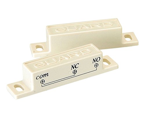
Does the locker door, reliably open/close when you need to switch on/off. A more robust and simpler solution would be to use a reed relay, which needs no power or circuitry at all. It just needs a suitably rated reed relay, in the door and a magnet, on the other side of the door (difficult to explain in words).
I.e. like they use in some burglar alarm window/door sensor switches.
Image for illustration ONLY. You need the correct, probably normally open type (or is it normally closed, I'm NOT sure in this application, which way round it goes, sorry), and suitable current rating parts. One end goes on the door, the other on the "wall" part of the locker. Potentially eliminating the entire rest of the circuitry.
You want closed when the units are separated and open when they are close together. I can't remember or don't know which way round they normally are.