hi everyone,
So for my next project i would need to have two switches controlled by RPi 4b GPIO pins. Since RPi pins are 3.3v and max current of 16mA, i have been researching viable solutions for a few days now.
There are plenty cheap MOSFET modules (Amazon, eBay...Ali) but i would really like to understand what i am using and how to properly use it, rather then just hook it up. I've learned so far that just because MOSFET seems to "work" that doesnt mean it works as it should and that the circuit is well designed for the purpose and safe.
So, first what i need:
1. I need a switch that would toggle 12V AC relay ON/OFF.I am using FINDER 48.62 relays, specs attached. It should draw some cca 100mA of current, i have figured i could use 2n2222 transistor for this, as shown on the schematic below:
Is this OK?


Screenshot 2021-12-21 114303.png
Screenshot 2021-12-21 114125.png
2. I need a switch to control LED strip, cca 3A - 4A of current.For this i have found many possible solutions but honestly i do not like any of them. Some claim to work straight from RPi 3.3V GPIO, some dont claim anything, some would work on 5V signal.
I could use low level trigger relay module with optocoupler, straight from RPi GPIO but i would prefer silent/no click solution, thus MOSFET is a perfect choice.
As already said, some MOSFET modules claim to support 3.3V signal and yes, they do "work" with 3.3V but as soon as i want to draw more than 1-2A of current they get hot, indicating they do not fully open and conduct, so some sort of level shifting to 5V has to be implemented.
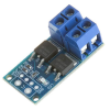
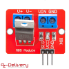
a) this solution includes ready made solutions like attached modules:
For this one, i should still use NPN/PNP transistors like in "b" solution from below, to shift to 5V...


61yu2ts7xtS._SL1000_.jpg
71241-KcfEL._SL1500_.jpg
b) this would be preferred solution and i can easily implement this, or even quickly design a PCB that would be reliable and have properly designed circuit. In this case i am using external 5V source, not the RPi 5V pin
The questions here is, how come there are no ready made modules featuring below schematic design, if that is a proper way to do it?
Image courtesy of
https://quadmeup.com/raspberry-pi-mosfet-high-power-switch/
Hi-power-switch_schem.png
Many thanks for any help in advance,
Alek