Author Topic: Super beginner; checking understanding of pull-up and -down resistors  (Read 1017 times)

0 Members and 1 Guest are viewing this topic.

Offline IslandDonTopic starter

  • Newbie
  • Posts: 5
  • Country: us
Hi, all. I'm really new to electronics, and I'm hoping to check my understanding of how pull-up and pull-down resistors work, especially when the switch (or whatever else) is open. Please let me know where I'm right and where I could understand better.

The basic idea is that if you don't have a pin on an IC connected to anything else in the circuit, you don't what the voltage (a.k.a. potential difference) between that pin and Vcc or ground are, so weird things might happen.

To avoid weird things, you put a resistor in parallel with the switch (or whatever else), which pulls the voltage at the pin close enough to Vcc or ground when it would otherwise float that it might as well be Vcc or ground. A pull-up resistor is connected to Vcc and causes the pin to be ≈Vcc when the switch is open; a pull-down resistor is connected to ground and causes the pin to be ≈0 when the switch is open. (As a result, an open switch causes a high voltage on the pin with a pull-up resistor and a low voltage with a pull-down resistor.)

Why that works is where I'm having a hard time. This all seems to depend on the current over the IC pin being "small." This may seem like an obvious question, but the current over two things that "consume" power in series has to be smaller than the current of either on its own, right? So the current of the IC on its own is the upper bound for the current of the IC in series with the resistor?
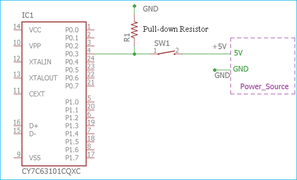
In this example from Circuit Digest, when the switch is closed, the voltage is =5v because voltage is the same in parallel. When the switch is open, because current is small, the voltage drop across the resistor is ≈0, so the voltage on the IC-side of the resistor is ≈0, so the voltage at the pin is pulled down to V≈0. Does that sound about right?


Similarly, with a pull-up resistor, as in this example from The Mad Science Notebook, closing the switch makes the pin's voltage =0v because voltage is the same in parallel. Does this also mean that all of current is being dissipated as heat by the resistor? (Except for the negligible current going through the IC because electricity is complicated?) The power of that heat would be very little because of the numbers involved, but not zero. And when the switch is open, because the IC uses very little current, the voltage drop is over the pull-down resistor is ≈0, so at the pin, V≈Vcc.


I've read in a bunch of places that a 10kΩ is kind of standard. The reason why it can't be arbitrarily small is obvious; you'd be effectively shorting Vcc to ground. Is the reason it can't be arbitrarily large because then V≈0 starts to become V≫0? Basically, you need to make sure the smallness of the current that the IC uses at Vcc can "overwhelm" the chosen bigness of the resistivity of the resistor. I know that's not the most technical language, as an intuitive understanding, is it correct?

I read also that there's something about how the resistivity affects the speed of the pin moving between Vcc and ground.

I'm looking forward to asking more questions in the future!
 

Offline rstofer

  • Super Contributor
  • ***
  • Posts: 9890
  • Country: us
Ask away!  That's why the forum exists.

Consider the popular Arduino chip, the ATmega328P

http://ww1.microchip.com/downloads/en/DeviceDoc/Atmel-7810-Automotive-Microcontrollers-ATmega328P_Datasheet.pdf

What you really need to know is how much current flows into the pin when it is high and how much current flows out of the pin when it is low.  Fortunately, these numbers are easy to come by and are quite low for CMOS circuits.  It's 1 uA in this case.

The current parameters are IIH and IIL and are in section 28.2 (page 259) lines 5 & 6 of the table.  While there, look at VIL2 and VIH2 (the top two lines).  You size the resistor such that when the current is flowing, the voltage drop across the resistor doesn't become so high that you can't make the voltage specs.  Again, for CMOS, this is no problem and we usually size the resistors at lower values just to prevent noise from disturbing the high impedance pin circuit.  I2R losses as a function of resistor value depend mostly on the percentage of time the switch is closed.  10k seems about right.

I leave it to you to size the resistors for something like the TTL 7400 chip.  You will find that pull-down resistor values have to be VERY low and this pull-down configuration is seldom used.

ETA:  Although 10k is often used, it might not provide enough current flow to keep the switch closed.  There are two problems:  Enough voltage to break through any oxidation and enough current to keep the connection 'glued'.  And, of course, there are good switches and not-so-good switches.  If you look, you can find high fidelity switches which feature bifurcated (think snake tongue, forked) gold plated contacts.  They are pricey.

Sometimes you just have to drop the resistor value to something less than 10k.  1k comes up from time to time.

ETA2:  CMOS inputs are somewhat capacitive.  As a result, the pull resistor forms an RC circuit with the internal capacitance and this slows the transition.  It usually isn't a problem.

If you look a little farther down the table, they tell you the maximum resistor value for the Reset pin (60k) and IO pins (50k).

Those datasheet writers are pretty thorough!
« Last Edit: June 05, 2020, 11:13:04 pm by rstofer »
 
The following users thanked this post: Old Printer

Offline BroMarduk

  • Supporter
  • ****
  • Posts: 78
  • Country: us
You're on the right track.

Someone a few weeks ago posted a link to this video (Simply Put YouTube Channel) that I have to agree is a great introduction to Pull Up and Pull Down resistors and why you need them and how to calculate the correct value you need.


« Last Edit: June 06, 2020, 07:52:40 pm by BroMarduk »
 
The following users thanked this post: IslandDon

Offline IslandDonTopic starter

  • Newbie
  • Posts: 5
  • Country: us
Ask away!  That's why the forum exists.

Consider the popular Arduino chip, the ATmega328P

http://ww1.microchip.com/downloads/en/DeviceDoc/Atmel-7810-Automotive-Microcontrollers-ATmega328P_Datasheet.pdf

What you really need to know is how much current flows into the pin when it is high and how much current flows out of the pin when it is low.  Fortunately, these numbers are easy to come by and are quite low for CMOS circuits.  It's 1 uA in this case.

...

Those datasheet writers are pretty thorough!

You're on the right track.

Someone a few weeks ago posted a link to this video (Simply Put YouTube Channel) that I have to agree is a great introduction to Pull Up and Pull Down resistors and why you need them and how to calculate the correct value you need.


Thank you both for the replies. The person who made that video is really excellent at instruction. It's all very clear and understandable! And the application of that video to the data sheet is pretty immediately obvious. I'm sure I'll refer back to this post in the future. Cheers!


Share me

Digg  Facebook  SlashDot  Delicious  Technorati  Twitter  Google  Yahoo
Smf