Hi all,
I'm building a driver for a linear solenoid - the intention is basically to make it possible to use a slightly over-spec supply voltage to make it knock as hard as possible, then have the voltage drop off to a reasonable holding voltage as quickly as possible. I'm almost there, I've just got some questions related to tweaking it.
I've based my circuit off the information found in
this excellent write-up. I've built "version 1" of the circuit, which works as expected (it's just a cap and a resistor in parallel after the solenoid), and I'm now building "version 2", which uses a PNP to short out the cap when voltage is removed, so that it's empty and immediately ready for another cycle, without having to wait for it to discharge. My circuit is just like the schematic on the above page, which is this:
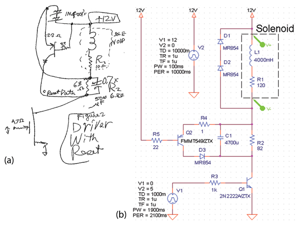
With the following differences:
- The solenoid is
this one (7R resistance)
- R2 is 7.5R
- Diodes are 1N5400
- Q5 is TIP42A
- For testing, I'm using a pushbutton instead of Q1
My issue is that when power is disconnected, the Base-Emitter voltage of Q2 doesn't go low enough to turn it on and short the cap. Of course, part of the problem is that I'm using a transistor with a too high V
BE(on) compared to the one in the original schematic - but looking at the Base-Emitter voltage on the scope, it doesn't really seem to go much below -0.7V, which wouldn't be enough even if I had the suggested transistor, which needs -1V.
I've adjusted the R4 and R5 values, but it doesn't make much of a difference. If I just use jumpers instead of R4 and R5, I do in fact (sometimes) get a low enough voltage to turn Q2 on, but this makes the whole circuit unreliable and is clearly not a good idea. Other resistor values (5R-33R) don't seem to make much of a difference, I still can't quite reach -1V, I just get more noise with lower resistance. Best I could do was -779mV, as per the attached scope shot.
So - I'll get the proper transistors, but apparently I need to do something else as well to make it work reliably. Any clues on what to adjust? Is there simply not enough energy stored in the solenoid to get sufficient flyback to turn Q2 on?


