Again, sorry for a late reply. I'll haveto figure out how to get email notifications from this forum.
Pictures:
https://goo.gl/photos/JsprsCm8LbY6HLvS6( It's the sub-board to the right in both pictures. The other board is just the debug stuff for it. Ignore the enormity of the wires on the debug-side, please.

)
Size: 25x25mm
Legend:
Large chip - Main MCU - STM32F030C8T6
SOT-3 chip - LDO - LM317EMP (this thing isn't using that much power, so I decided to go for a KISS principled design here.
QFN chip - RF Transceiver - Nordic Semiconductor nRF24L01+
P1 8x3 holes - The servos connects here. 8 channels, three pins each.
In the planned future, there will need to be an LNA on there as well to get more range.
I have no case/mounting for it yet, as I was unsure about what to do about vibrations.
I could probably make the board single-sided, as there's not that much on the bottom. Maybe replace the enormous LM317 with something smaller, and squeeze in that LNA as well?
Now, for some answers:
G-forces - For pro pilots like in the video, it should be around 10G substained, and up to 25G peaks. From first hand experience, it will launch your receiver battery right out _through_ the fibre-glass canopy if you don't fasten it securely.
Weight - It's a factor, but less than one might think. Keep it under 100-150 grams, and it won't be a problem at all.
Something other than a crystall - I use the internal RC on the STM32, but the RF chip needs some kind of precision time-source. I'll look over the datasheet and see if I can use an oscillator instead as suggested earlier.
Board orientation - "It varies", as people all mount them differently to get more efficient cabling to the servos, gyros, sensors, etc. However, it's almost always perpendicular to one of the three axises.
Power on the board - Very little. Using shitty servos that pull some current from the signal lines, I've seen ~100mA draw from my board. Good thing I have a 1.5A LDO on there..
As for in-situ, I stopped flying myself a few years ago, and don't even have my equipment here. However, this is a typical setup for an electric heli:
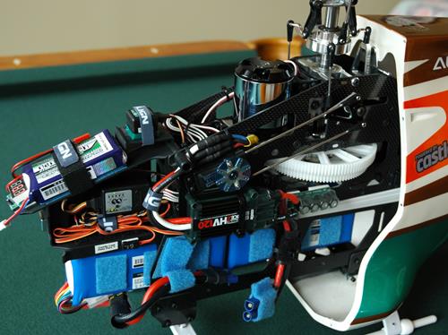
The thing I'm making would actually not even be visible in this picure. It's probably stuffed between the two CF plates that the battery is mounted beneath.
Fuel-heli vs. Electric - Actually, once LiPos came to the market, the electrics are on-par with the fuel ones in performance, and in some cases better (wider power-band).


