I've created a PCB for my newly built 3D printed Windmill. Now I am not entirely sure about all the components and the way they function, so I'd like to have your opinion on the circuitry before I place my order.
The idea is that the circuitry charges an
externaly protected and managed 18650 and stores sudden current spikes inside the a capacitor (C1). The battery management circuitry requires a voltage of 3.7V and specifies 9A max (Aliexpress protector board, so I'm expecting around 4.5A max charging current).
The board should be able to recover from a total black-out using only the the generator's power, so the generator must be able to power the required chips (U4) to store the power into the battery. I think I did this right.
I expect a maximum of 20V@6A to ever come from the BLDC under load, which will probably only occur during a tornado. You can find the BLDC here:
https://aliexpress.com/item/32834130958.html?spm=a2g0s.9042311.0.0.27424c4dvEScG2.

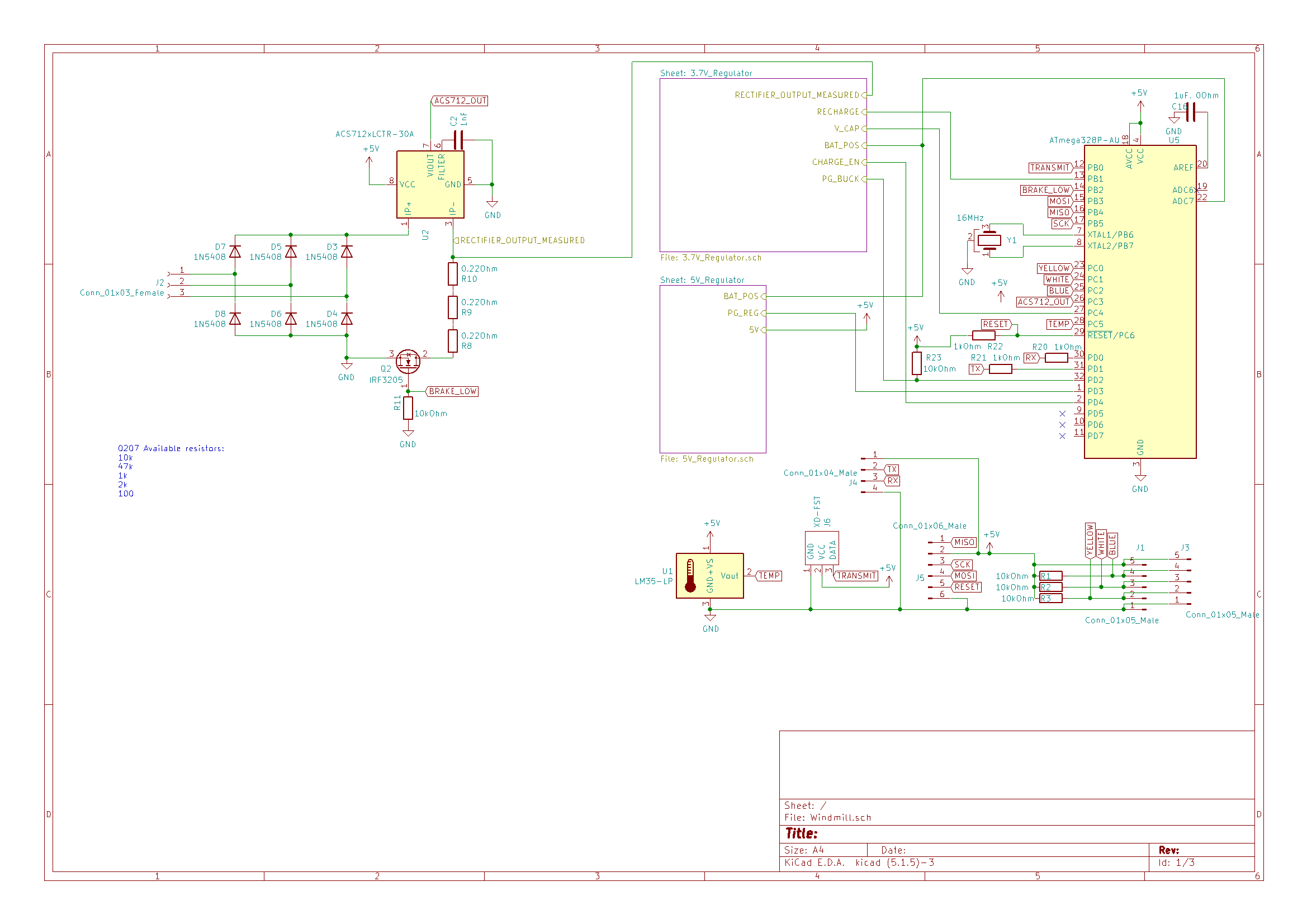
The schematic requires some comments.
The power from the BLDC comes in through connector J2 and goes through a diode rectifier bridge (D3-D8) In order to have the capability to slow the BLDC down, I've added three 0.22 Ohm power resistors in combination with a N-Channel mosfet (Q2) to control the speed of the motor in a high wind force push event.
To enable/disable charging the capacitor, another N-channel mosfet (Q1).
U4 requires an logic level enable signal and VIN (5V-40V) can be used; I'd like to control the charging, so I added a pull-up (R25) to the enable line and a schotky diode (D2) after the pull-up to protect the 328P from the 5V-40V that might be on VIN. Is this the proper implementation and can I enable (5V@CHARGE_EN) and disable (0V@CHARGE_EN) U4 using this layout? I've done some simulations using LTSpice but they only gave me more doubt.
I'm still in doubt if I'll implement this method for Q1, to make sure that the default state of Q1 is on until the 328P wakes up.
To get the voltage of the current spike cap, a voltage divider is used (R4-R6).
A current sensor is integrated onto the PCB to monitor the current.
U3 is the 5V system power supply, which provides power to the MCU and various sensors. The idea is that this power supply is able to wakeup on it's own, without the MCU running. (WeBench design:
https://webench.ti.com/appinfo/webench/scripts/SDP.cgi?ID=8BDB047EA3CA84C8)
U4 is the battery power supply, which converts the input voltage to 3.7V. (WeBench design:
https://webench.ti.com/appinfo/webench/scripts/SDP.cgi?ID=3C967BFA6477601C)
A temperature sensor is also present to monitor the temperature inside the windmill.
The connectors:
- BT1: the battery connection terminals.
- J2: the 3 phase BLDC input.
- J3: the magnetic sensor header for the BLDC.
- J4: the UART header.
- J5: the ICSP header.
- J6: the 433 MHz radio transmit module.


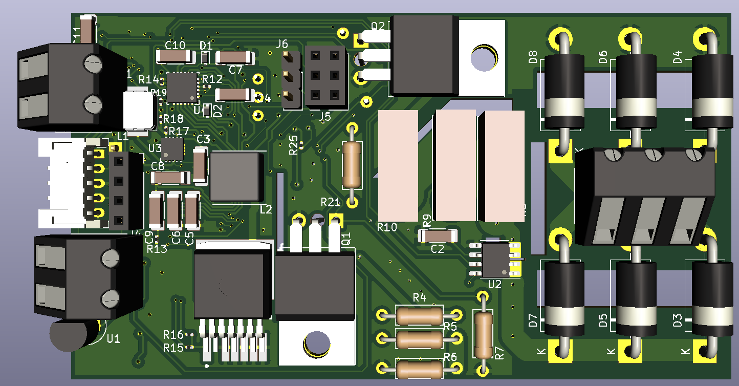
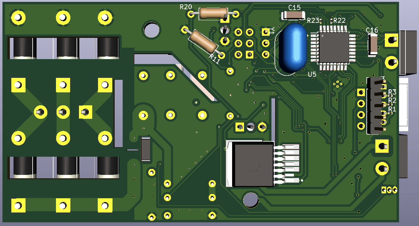
The screw terminals visible are not the ones that will be used.
There is a cut-out between the current in and current out pins of the ACS712 which also goes underneath the chip it self. The 3 pin mosfets use the tap for the drain instead of pin 2, the solder mask has been removed underneath the taps.
Those big blocks next to the diode bridge are the power resistors that dump the energy when needed. (0.22 Ohms, 5W each. They are bendable and you can solder an additional resistor to the top of each resistor, so in total 5 power resistors can be used, the middle one is too high to solder another resistor onto.)
I simulated the break dump in LTSpice and that looked promising.
I ran the DRC and everything is solved and passes the checks.
My questions;
- Have I implemented the mosfets (Q1 and Q2) properly (I don't mean the mosfets used around U3 and U4)
- Is the board able to start charging the battery, or wake-up the 328P, from a complete black-out?
- What do you think of the schematic and the PCB?
- Do you spot any cricital faults?
Block diagram of the windmill's circuitry
