I've been playing around with building up an SMPS for a project using the MC34063, though I have considerable doubts about the stability of the output voltage on this device. Anyway, I recently saw some posts either here or on youtube about breadboard-related noise and thought I'd post some related images from my scope.
R1 is on a breadboard, 1/U is on a protoboard. Same circuit - 9V output. 47uF output cap - the equations turned up a minimum 25uF. I have to use an obscenely large cap to get that shark fin down to a reasonable level (I *think* I was able to get it down to 100mV p-p with a 1000uF cap, but I wouldn't stake my life on that).
Also it was an excuse for me to learn how to save reference waveforms.
The above was without a load (and I should probably mention this was all done w/ DC coupling and the normal ground clip on the probe). Here's the same with the design load.

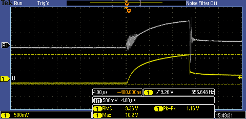
And finally, probably with no load, but with the horizontal scale such that you can actually see/measure the frequency of the sharks:

That's 1.06V p-p and a noise frequency of 354.1 Hz (I really should have made sure the markers were on the freq rather than the p-p measurement, but oh well).
The formula tables said I should use a 391.84pF timing cap, and I ended up using a 390pF cap. If the signal on pin 3 was any indication, the switching frequency was only ~70KHz rather than the intended 100KHz. Ah well, it made for an interesting learning experience but I think I'm unlikely to use it in the project I'd intended.


