I was impressed by the DS1052E I had recently purchased and I got myself a
brand new one. But, alas, it seems that the new device has some serious issues my previous one did not have; neither I have the older DS1052E in my possession anymore...
Explaining myself: The new DS1052E seems to have a higher noise floor than the older one and whenever any probe tip touches the ground of the device, the display is instantly filled with some kind of very high frequency sinusoidal noise in the range of 95MHz, making practically unable any measurements to be done; especially in the lower voltage ranges.
For example, the older device could easily read the noise of its own PSU, by simply touching the probe tip to the front USB +5V line, and it showed clearly the PSU oscillator pattern without the need of any kind of signal filtering; even with the probe's ground lead floating. The new one is totally unable to take the same reading because every time the probe tip touches the ground (or the +5V line) the aforementioned 95MHz noise covers any possible input signal; input filtering does not really help. I cannot even read the 1.0KHz probe calibration output signal without some serious filtering. Even with the use of the probe
ground spring, the device does not return the clear-cut waveform my previous instrument did. I do not know what is wrong but I suspect that there is some kind of a hardware issue.
I will let the snapshots speak for themselves:

Noise 1: Probes disconnected
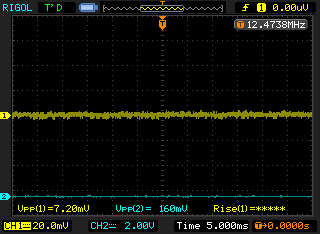
Noise 2: Ch1 probe connected. Notice the frequency counter.

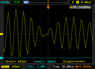
Noise 3: Ch1 probe-tip grounded through probe's GND lead. 95.8MHz?
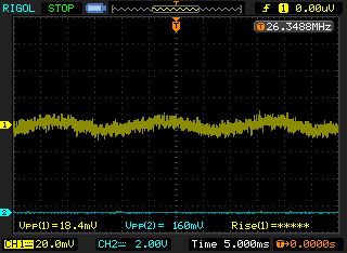
Noise 4: Ch1 probe-tip grounded through aluminium foil. 12.47MHz?

Noise 5: Ch1 probe on the probe calibration output: Unacceptable!

Noise 6: Ch1 probe on the probe calibration output, filtered. Still fuzzy for such a clear signal...

Noise 7: Ch1 probe on the probe calibration ground.
Noise 8: Ch1 probe on the probe calibration ground, displayed in a proper time-scale.
After a brief search, I found out that this is not an isolated case, since
another brand new DS1052E had the same exactly symptoms a year ago; so the issue is independent of the new ADC markings (see below). Since I have not purchased the instrument from a Rigol authorised dealer, I do not expect to have it replaced; so, I opened it in hope of finding something that can be fixed.
The mainboard (ver. 0.2 2008/05, build 11/03) is a multi-layer PCB (the bottom layer is marked as sixth and the fifth layer mark is visible beneath it, so it is a three --at least-- layer PCB); and this fact alone rules out any serious attempt to check the PCB for any possible routing faults. So, I begun searching for inconsistencies.
It is interesting that, though the AD8370 and the LMH6552 within the analog front-end shielding retain their diacritics grinding-out, this is not the case for the ADC chips anymore! The five ADCs proudly present their identity now, being devices manufactured from AD and waving their obscure identity in three lines:
RAD0182A
#1032
1924219.1
I suppose that the second figure is the mfg. time-code (32nd week of 2010).
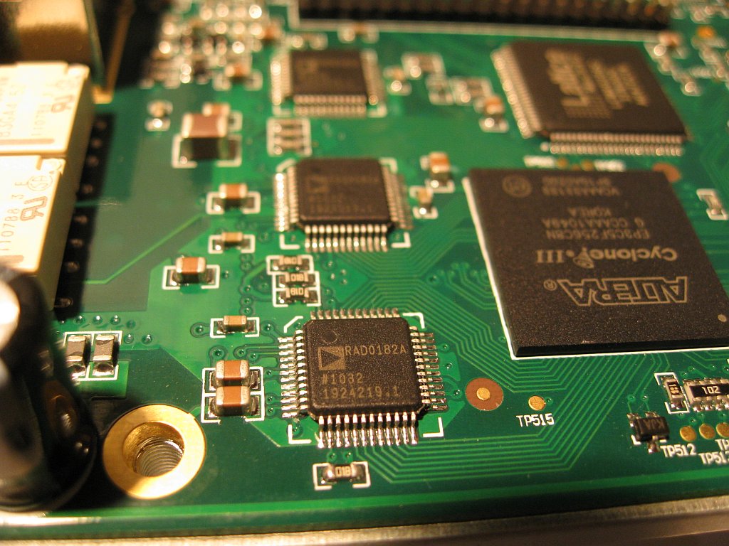
DS1052E new ADC markings!
Of course, I guess that if I purchased those quantities of the AD9288 ADC chip Rigol does from AD, the latter ones would be happy to put a picture of my face onto the chip instead of the traditional boring identification marks!
With the help of a bit of *ahem* reverse engineering I drew the schematics of the PSU (sorry I got lazy and did not fire up the CAD-CAM), which seems to be functioning as expected (according to the biasing component values):

DS1052E PSU schematic. (Go to the last picture at the end of the message for a high resolution image of the schematics)
Taking a few readings, the PSU generates the following:
1. The main supply, which is 6.40V and powers almost everything.
2. A 3.375V supply for the logic section, which is generated from the 6.4V by an LM317T.
3. A 15.0V supply for the analog section.
4. A negative supply of -12V for the analog section and the cooling fan.
Now, why the main supply is 6.4V? That is simply because the 5.0V partial supplies can be accurately generated locally on board, independently of the long wiring/routing losses.
But, why this peculiar voltage of 6.40V
exactly? Well, because this specific voltage is what exactly required by the
LCD module backlight!
Anyway...
Any thoughts or suggestions on the unacceptable noise issue the brand new device has are welcome.
-George
P.S. By the way, it is fun to be right! I
have previously speculated that the actual power consumption of the instrument would probably lie between 10..15W. Well, these are the actual readings I took from the PSU of my unit:
A: 6.40V x 625mA = 4000mW
B: 3.40V x 1195mA = 4063mW
C: -12V x -335mA = 4020mW
D: 15V x 21mA = 315mW
E: LCD backlight: 5.98V x (447mV/5.6Ω) = 477mW
Total power consumption (by the instrument ONLY, without the PSU losses): A+B+..+E = 12.87W!
Well, yes, it is fun to be right, indeed!


