This is an updated post.
The information corresponds to the modified module.
Only + 5V power supply is used.
The problem that was discussed up to 8 post is REDACTED. Fully working.Hello All! That will be my first topic here.
Immediately I apologize for my English, I use Google translate.
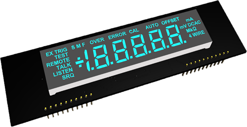
I present to your attention LED DISPLAY MODULE FLUKE 8840A / 42A (DIY kit).
-replace-broken-damaged-vfd/?action=dlattach;attach=1224639;image)
This story began a year ago, like many of you, I bought a FLUKE 8840A on eBay with a broken display.
The search for solutions to replace it did not lead to special results.
It was decided to develop our own LED module with a custom LED display.
ASSIGNMENTThis LED display module can be used to replace your broken, damaged, cracked, unusable, etc. VFD (itron CP2067A ) of FLUKE 8840A and 8842A multimeters. (FLUKE PART NO. 728873(FLUKE STOCK NO. 680843)).
This LED display module is intended for hobbyist simulation of various measurement devices, as well as for educational purposes, and provided AS IS as a DIY kit.
In addition, this display module can be used in electronics hobby projects, where a 5.5 seven-segment display with indication of additional characters is required.
DESCRIPTIONThe LED display module is designed as close as possible to the original and does not require any modification to the multimeter. The module is mounted in place of the dismantled non-working VFD display.
The control scheme for one segment is shown in Fig. 1.
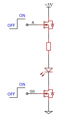
Fig.1
This module uses a custom-made, industrially produced 7-segment display.BASIC TECHNICAL SPECIFICATION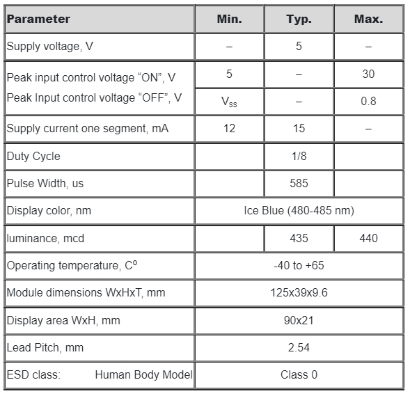 BOM
BOM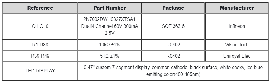 FRONT PANEL DESIGN AND ALL LIGHT ON SEGMENT FEATURE
 Pin assignment
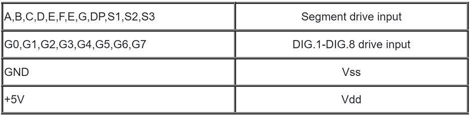
Before shipping, each module is assembled (excluding the pin header) and tested. I guarantee a long service life provided that the consumer observes the conditions of transportation, storage and installation.
This kit has been tested with FLUKE 8840A and FLUKE 8842A multimeters.
INSTALLATION-replace-broken-damaged-vfd/?action=dlattach;attach=1233345;image)
-replace-broken-damaged-vfd/?action=dlattach;attach=1233349;image)
-replace-broken-damaged-vfd/?action=dlattach;attach=1233351;image)
-replace-broken-damaged-vfd/?action=dlattach;attach=1233354;image)
-replace-broken-damaged-vfd/?action=dlattach;attach=1233356;image)
-replace-broken-damaged-vfd/?action=dlattach;attach=1233358;image)
-replace-broken-damaged-vfd/?action=dlattach;attach=1233360;image)
-replace-broken-damaged-vfd/?action=dlattach;attach=1224645;image)
-replace-broken-damaged-vfd/?action=dlattach;attach=1233339;image) Photo of the installation in full resolution follow the link
Photo of the installation in full resolution follow the link
https://drive.google.com/drive/folders/17eKHPnh537Mgt9A4NKM6ya5zAWMvPNiQI am the developer and sole producer of this module.
All other solutions on the market use the module purchased from me.
I only sell on eBay under a nickname:
grudn_2015
My shop on eBay:
https://www.ebay.com/str/aholstoreThe price at which I sell the module (without shipping and taxes): - $34.4The LED display module is sold here: https://www.ebay.com/itm/155853129116Thank you for your interest!
Good luck with your research and measurements!


