Author Topic: 10 mV Differential signal RFI filters  (Read 492 times)

0 Members and 1 Guest are viewing this topic.

Offline loop123Topic starter

  • Frequent Contributor
  • **
  • !
  • Posts: 297
  • Country: ca
10 mV Differential signal RFI filters
« on: February 25, 2024, 11:38:36 pm »
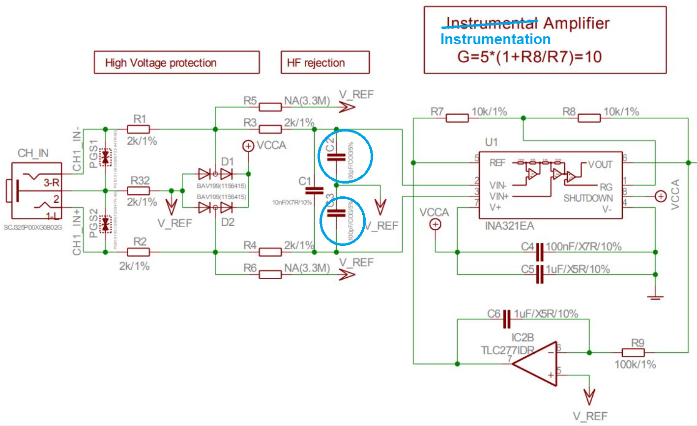
I want to avoid building a large Faraday Cage that can costs thousands of dollars. So I plan to just use RFI filters in the differential input stage of my bioamplifiers or any I'd use without any filter to avoid clipping the output or any nonlinear effects. I saw this RFI filter used by Olimex.
2036462-0

https://www.olimex.com/Products/Duino/Shields/SHIELD-EKG-EMG/resources/SHIELD-EKG-EMG.pdf

It uses simply low pass RC filters. Is it already the optimum design? Can you give other designs used in other amplifiers?  How can one add for example ferrite beads into it? My observations:

1. The capacitors in each common mode input must be exact or tolerance of 0.001%. If they differ, it can introduce differential signal. For the differential capacitor. I guess any will do.

2. To look for resistor and capacitor i'll use in both common mode (C2, C3) and differential (C1).  Must I focus on the frequency only and not so much on the voltage? For example. My maximum input is only 10mV. So I can use the same resistor and capacitor in the low pass RC filter used in say 10000V equipment if the frequency cutoff is the same?

3. If the source of the interference is line and radiated. The filter can filter both? My focus is filtering radiated intereference because I only used batteries.

4. Should I look for cutoff in the 1Mhz region or all above 10kHz? What values of resistor and capacitor must I get? One with tolerance of 0.0001% to avoid causing differential signal in the mismatch.

5. In a Faraday Cage. What is the minimum frequency it can allow? Please give picture of an actual table size Faraday Cage. I want to know how opaque it is or transparent and how you insert your hands inside the cage.

Thank you.
« Last Edit: February 25, 2024, 11:57:30 pm by loop123 »
 

Offline David Hess

  • Super Contributor
  • ***
  • Posts: 16620
  • Country: us
  • DavidH
Re: 10 mV Differential signal RFI filters
« Reply #1 on: February 26, 2024, 02:24:51 am »
1. The capacitors in each common mode input must be exact or tolerance of 0.001%. If they differ, it can introduce differential signal. For the differential capacitor. I guess any will do.

That is definitely a problem.  The solution is usually to make sure that the cutoff frequency of the common mode filter is much higher than the signal bandwidth of interest.  The filter is only used to block radio frequency interference.

Low pass filtering, if required, is implemented *after* the differential to single ended conversion, or with a differential mode filter although this will convert some of the differential signal to common mode reducing common mode rejection.
 

Offline loop123Topic starter

  • Frequent Contributor
  • **
  • !
  • Posts: 297
  • Country: ca
Re: 10 mV Differential signal RFI filters
« Reply #2 on: February 26, 2024, 02:39:06 am »
1. The capacitors in each common mode input must be exact or tolerance of 0.001%. If they differ, it can introduce differential signal. For the differential capacitor. I guess any will do.

That is definitely a problem.  The solution is usually to make sure that the cutoff frequency of the common mode filter is much higher than the signal bandwidth of interest.  The filter is only used to block radio frequency interference.

Low pass filtering, if required, is implemented *after* the differential to single ended conversion, or with a differential mode filter although this will convert some of the differential signal to common mode reducing common mode rejection.

Were you referring to C1 (see original figure) in the differential mode filter thing? I know how common mode can convert to differential signal. But how could it "convert some of the differential signal to common mode"?

Also for 1mV to 10mV. What kind of radiated EMI (do you refer EMI only to line intereference or can it be radiated too?) or radiated RFI that is strong enough to disturb the 1mV to 10mV? Does this really happen at all?  What must be the strength of the RFI to cause the 1mV to 10mV to become distorted or clipped like this (it's just example I saw elsewhere, ignore the frequency of the red sine wave):

2036651-0

Supposed the green sine wave (top) is the 1mV signal. And the red sine wave is the RFI (radiated). What strength of the RFI before it can clip the 1mV signal such that the output (at bottom) would become distorted?

I'm talking of radiated RFI interference, not from EMI from power supply lines because I used batteries, so it is disconnected from main.

« Last Edit: February 26, 2024, 02:45:15 am by loop123 »
 

Offline David Hess

  • Super Contributor
  • ***
  • Posts: 16620
  • Country: us
  • DavidH
Re: 10 mV Differential signal RFI filters
« Reply #3 on: February 26, 2024, 03:06:45 am »
Were you referring to C1 (see original figure) in the differential mode filter thing? I know how common mode can convert to differential signal. But how could it "convert some of the differential signal to common mode"?

I am actually not sure now what I had in mind when I said that.

Quote
Also for 1mV to 10mV. What kind of radiated EMI (do you refer EMI only to line intereference or can it be radiated too?) or radiated RFI that is strong enough to disturb the 1mV to 10mV? Does this really happen at all?  What must be the strength of the RFI to cause the 1mV to 10mV to become distorted or clipped like this (it's just example I saw elsewhere, ignore the frequency of the red sine wave):

It could be radiated EMI that gets into the input, or conducted EMI.

What happens is that the RF at the input gets rectified by the input transistors or other active devices which causes a shift in offset voltage.  This is just AM detection.

If there are multiple RF frequencies, then non-linearities in the input stage can mix them to produce low frequency interference.
 

Offline loop123Topic starter

  • Frequent Contributor
  • **
  • !
  • Posts: 297
  • Country: ca
Re: 10 mV Differential signal RFI filters
« Reply #4 on: February 26, 2024, 04:43:45 am »
Were you referring to C1 (see original figure) in the differential mode filter thing? I know how common mode can convert to differential signal. But how could it "convert some of the differential signal to common mode"?

I am actually not sure now what I had in mind when I said that.

Quote
Also for 1mV to 10mV. What kind of radiated EMI (do you refer EMI only to line intereference or can it be radiated too?) or radiated RFI that is strong enough to disturb the 1mV to 10mV? Does this really happen at all?  What must be the strength of the RFI to cause the 1mV to 10mV to become distorted or clipped like this (it's just example I saw elsewhere, ignore the frequency of the red sine wave):

It could be radiated EMI that gets into the input, or conducted EMI.

What happens is that the RF at the input gets rectified by the input transistors or other active devices which causes a shift in offset voltage.  This is just AM detection.

What? can you help illustrate what you mean? did AM means Amplitude Modulation? what detection of AM and how can it exactly cause a shift in offset voltage?

Quote

If there are multiple RF frequencies, then non-linearities in the input stage can mix them to produce low frequency interference.

Does this happen in a typical city with ambient background electromagnetic environment with hundreds of radio stations, tv stations, cellular tower all around, or does the non-linearities only occur when you are directly below a microwave disc, radar or the like? Can someone give examples of actual waveforms of the RFI interferences? If your device has no input filters of any kind. It's totally or almost useless?
 

Offline Andy Chee

  • Frequent Contributor
  • **
  • Posts: 686
  • Country: au
Re: 10 mV Differential signal RFI filters
« Reply #5 on: February 26, 2024, 08:38:33 am »
This is one example of radio frequency interference ("QRM" is amateur radio shorthand for man-made interference)

https://youtu.be/Pwbk8yP6SIk?t=168  (start watching the video @2:48)
 

Offline David Hess

  • Super Contributor
  • ***
  • Posts: 16620
  • Country: us
  • DavidH
Re: 10 mV Differential signal RFI filters
« Reply #6 on: February 26, 2024, 03:06:18 pm »
Quote
What happens is that the RF at the input gets rectified by the input transistors or other active devices which causes a shift in offset voltage.  This is just AM detection.

What? can you help illustrate what you mean? did AM means Amplitude Modulation? what detection of AM and how can it exactly cause a shift in offset voltage?

Yes, I mean AM as in amplitude modulation, but a train of RF pulses like from a TDMA phone also counts as amplitude modulation.

The RF modulates the conductivity of active devices like diodes and transistors and their non-linearity rectifies the RF.

Quote
Quote
If there are multiple RF frequencies, then non-linearities in the input stage can mix them to produce low frequency interference.

Does this happen in a typical city with ambient background electromagnetic environment with hundreds of radio stations, tv stations, cellular tower all around, or does the non-linearities only occur when you are directly below a microwave disc, radar or the like? Can someone give examples of actual waveforms of the RFI interferences? If your device has no input filters of any kind. It's totally or almost useless?

Microwave emissions are less of a problem.  HF, VHF, and UHF are usually the worst.  Generally you have to be pretty close to the transmitter, but this includes devices like cell phones.

A small amount of RF filtering can have a large beneficial effect.


Offline loop123Topic starter

  • Frequent Contributor
  • **
  • !
  • Posts: 297
  • Country: ca
Re: 10 mV Differential signal RFI filters
« Reply #7 on: February 26, 2024, 10:25:05 pm »
Quote
What happens is that the RF at the input gets rectified by the input transistors or other active devices which causes a shift in offset voltage.  This is just AM detection.

What? can you help illustrate what you mean? did AM means Amplitude Modulation? what detection of AM and how can it exactly cause a shift in offset voltage?

Yes, I mean AM as in amplitude modulation, but a train of RF pulses like from a TDMA phone also counts as amplitude modulation.

The RF modulates the conductivity of active devices like diodes and transistors and their non-linearity rectifies the RF.

Quote
Quote
If there are multiple RF frequencies, then non-linearities in the input stage can mix them to produce low frequency interference.

Does this happen in a typical city with ambient background electromagnetic environment with hundreds of radio stations, tv stations, cellular tower all around, or does the non-linearities only occur when you are directly below a microwave disc, radar or the like? Can someone give examples of actual waveforms of the RFI interferences? If your device has no input filters of any kind. It's totally or almost useless?

Microwave emissions are less of a problem.  HF, VHF, and UHF are usually the worst.  Generally you have to be pretty close to the transmitter, but this includes devices like cell phones.

A small amount of RF filtering can have a large beneficial effect.

How do you compute the strength of radiated RFI/EMI that can cause interference to 10uV and 1mV input signal? Because I guess if the RFI are so low strength, it can't make the 10uV or 1mV ride on the signal at all (see my original illustration)? Then they occur out of phase with the 10uV/1mV still at origin and the tiny interference also at origin, and no clipping can happen since the low strength RFI can't carry the heavier signal up and down?
 

Offline David Hess

  • Super Contributor
  • ***
  • Posts: 16620
  • Country: us
  • DavidH
Re: 10 mV Differential signal RFI filters
« Reply #8 on: February 27, 2024, 02:43:07 pm »
How do you compute the strength of radiated RFI/EMI that can cause interference to 10uV and 1mV input signal? Because I guess if the RFI are so low strength, it can't make the 10uV or 1mV ride on the signal at all (see my original illustration)? Then they occur out of phase with the 10uV/1mV still at origin and the tiny interference also at origin, and no clipping can happen since the low strength RFI can't carry the heavier signal up and down?

The RFI only has to affect active devices like transistors, which may multiply its effect in exceptional circumstances.

I think there are too many variables to calculate it.  Small changes in circuit design can have a large effect and small amounts of RFI protection make a huge difference.  Where it was an issue, I did empirical testing to measure susceptibility.


Share me

Digg  Facebook  SlashDot  Delicious  Technorati  Twitter  Google  Yahoo
Smf