Having no DC bench power supply at all I've been scouring EBay for deals on older BK Precision models. I have this strange obsession for a triple or quad output and the prices for those type of modern units were just too far out of my reach at the moment. I had set my sights on a new, old stock BK Precision 1650 (2 x 0-25v @ 0.5a, 1 x 5v @ 5a) as my starter supply but the listing had ended. The fellow said he would re-list it in a week or so but fate intervened and I stumbled across another supply the day before he re-listed:
Pardon the ghetto desktop random-bits-of-wood stand that it's on at the moment; in progress house renovations (I'm sure Dave can sympathize) have left me with about 8 square feed of space for my computer/electronics lair.
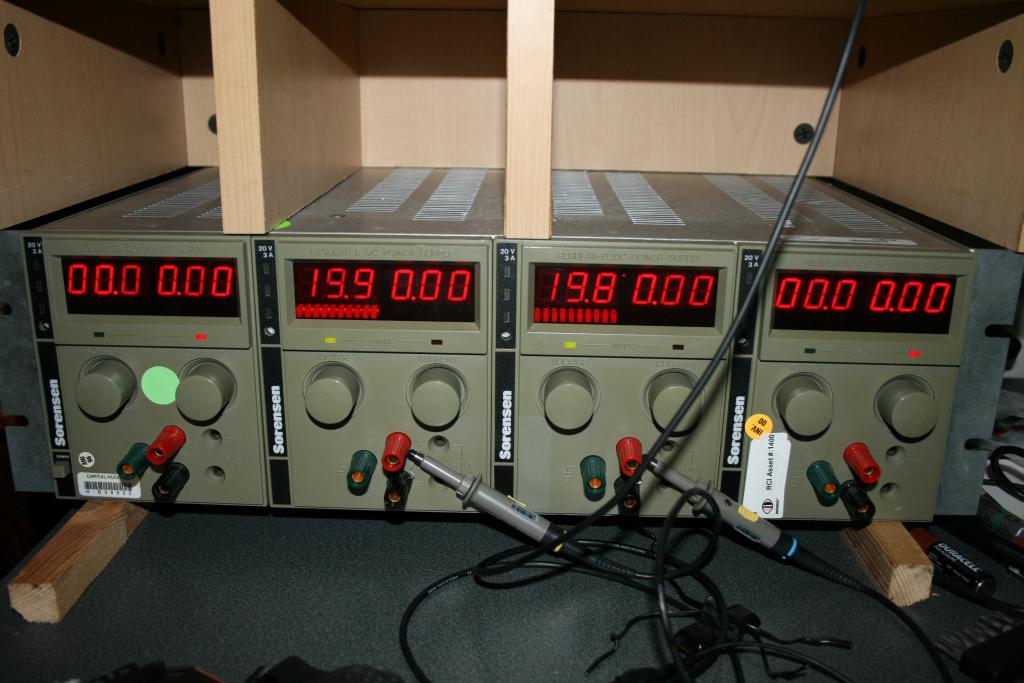
It's a Sorensen XTQ 20-3 with remote analog programming cards. The 4 supplies can be independent, series or parallel (though you manually have to set this up with wiring) and support CV/CC and current limiting. It also has "sense" connections that are used to compensate for losses in the output power leads. Unfortunately it doesn't have the option installed for the master/slave tracking but I'm thinking down the line I can use a microcontroller to accomplish this via the remote programming interface. The voltage pot is a 10 turn pot and the current pot is a single turn. Apparently the 10 turn current pot was another "option" that isn't on this unit.
The "Sorensen, A Raytheon Company" on the back places it in the late 80's early 90's but the specs that I could find were quite good and the unit seemed fairly operational. The line/load current regulation specs seem to be better on this old unit than the new $500 units (and 4 x $500 is a buttload of bills)! I figured that even if only 2 of the 4 PS's were operational that it would still be a decent deal. I got the unit for $150 shipped though I had to buy a manual for an additional $25 from someone else as I couldn't find it on the net. Fortunately the manuals from back then actually have schematics and theory of operation descriptions! Apparently all calibration is done by replacing specific socketed components of identical value.
The display reading on units 2 & 3 constantly "wander" (e.g. randomly fluctuating from 19.7V to 21.9V when set at 20V) and there's a nice transformer hum (a tad louder than the Rigol's fan) though the outputs are rock solid. All units output 0-20V and 0-3A. I can't tell how accurate the voltage/displays are until the Agilent meter shows up next week ( thanks to Russel for the heads-up! ) but on my Radio Shack meter (4k count, 0.3% DCV accuracy) shows the output rock solid and the meters off a little (e.g. Setting all units to 10V according to the meter read: 10.1, 8.9-10.8 (wanders), 8.8-10.9 (wanders), 10.0)
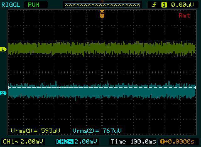
I've attempted to measure the ripple on the Rigol and, assuming the settings I used are correct for measuring this, these are the results (probes 1x, y = 2mV, x = 100ms):
Unit 1 & 4
Unit 2 & 3
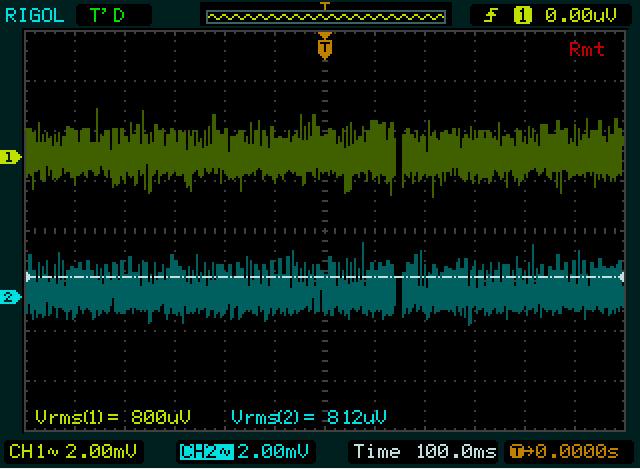
I used the spring clip on the probes instead of the alligator clips attached as seen in the picture above. Doesn't seem to me to be damned good for 20+ year old supplies. The manual spec is < 1mVrms.
If anyone can suggest other tests to run on the units, let me know (and explain how!). I will be able to better determine the voltages when the Agilent meter arrives this coming week.
I'll post some internal teardown pictures if anyone is interested.
Take care,
John


