Poll

What version would you build/use the most?

15V 8A parallel or 30V 4A series
30V 4A parallel or 60V 2A series
30V 8A parallel or 60V 4A series (probably difficult with heat design and whatnot.)

Author Topic: DIY Power Supply Build  (Read 63003 times)

0 Members and 1 Guest are viewing this topic.

Offline JoshuaTopic starter

  • Regular Contributor
  • *
  • Posts: 194
  • Country: us
Re: DIY Power Supply Build
« Reply #50 on: September 05, 2011, 12:50:50 am »
Thanks for the reply. I understand your point. The perfectionist in me wants to 0.00 - 30.00  :P    I guess I just thought that when looking about making my own supply, I seen alot...'A supply that goes down to zero is very useful.' I suppose that when they said 'zero' they just meant 'zero-enough'.


Also, I have done some measurements and found something that appears to be significant. I will post shortly...


Online IanB

  • Super Contributor
  • ***
  • Posts: 11885
  • Country: us
Re: DIY Power Supply Build
« Reply #51 on: September 05, 2011, 12:55:33 am »
This is an area where you would switch to a more specialized tool. Generating regulated voltages in the mV or uV range may have uses, but you would not use a general purpose bench supply for that, you would use a more specialized power supply specifically for that job.
 

Offline JoshuaTopic starter

  • Regular Contributor
  • *
  • Posts: 194
  • Country: us
Re: DIY Power Supply Build
« Reply #52 on: September 05, 2011, 01:16:23 am »
This is an area where you would switch to a more specialized tool. Generating regulated voltages in the mV or uV range may have uses, but you would not use a general purpose bench supply for that, you would use a more specialized power supply specifically for that job.


Aaaah, gotcha. Thanks for clearing that up.


I connected an led across the output in series with a 220R resistor. Here is a graph of the mA over voltage


The only thing that was adjusted to create this graph was the voltage-regulator potentiometer. As the voltage grew, so did the current. Once the current got to about 20mA, it grew no further. Also, at that point the voltage was about 6.4. I could not increase the voltage any further as well. Turning of any pots availed nothing. I could not increase the voltage at all, or the current. Only by lowering the voltage below ~6.4 could anything change. What could this mean?


When there is no load connected I can adjust the voltage all the way up to 30v.


Joshua
 

Offline Richard W.

  • Regular Contributor
  • *
  • Posts: 149
  • Country: de
Re: DIY Power Supply Build
« Reply #53 on: September 05, 2011, 08:01:50 pm »
Quote
Also, would somebody that understands the circuit care to explain what the two LEDs represent? Sometimes they are on, and sometimes they are not.

LED D13 is on, when the power supply operates in constant voltage mode. (In this case you controll the output voltage. The current is only limited by the load or the capatibilities of the supply)
This led should be on, even if you have connected a load or not.


LED D12 is on, when the power supply operates in constant current mode. (In this case, you controll the current which flows to your load)
This led is on, when you have connected a load, and reduce the current with the current control

This LED also indicates, when you want to draw more current than possible.

For the troubleshooting:

What's the voltage at C12?
What's the voltage at C7?
What's the voltage at C8?

Have you chosen the right resistors from "Tabelle 2" ?
Which resistors have you used as R30 / R31 ?
« Last Edit: September 05, 2011, 08:23:42 pm by Richard W. »
 

Offline JoshuaTopic starter

  • Regular Contributor
  • *
  • Posts: 194
  • Country: us
Re: DIY Power Supply Build
« Reply #54 on: September 06, 2011, 01:10:01 am »
[/size]
LED D13 is on, when the power supply operates in constant voltage mode. (In this case you controll the output voltage. The current is only limited by the load or the capatibilities of the supply)This led should be on, even if you have connected a load or not.LED D12 is on, when the power supply operates in constant current mode. (In this case, you controll the current which flows to your load)This led is on, when you have connected a load, and reduce the current with the current controlThis LED also indicates, when you want to draw more current than possible.
[/color][/size][/font][/size]


Thanks for the reply. So D13 is on when I am in constant voltage mode. I can adjust the voltage all the way up from 0 - 30v and the light should be on regardless of load or no load. D12 is on when the current limiting has come into play. If I lower the current level with the pot, it should come on when I reach that value. I.E., if I connect a load that will pull 1A and I have my current limit set to 500mA, the supply will only allow 500mA to flow, and the led will light indicating that it is actually limiting current. Is all that right?  To clarify, is the current function constant current, or current limit?
I mean, will the supply only cap the max amount of current allowed, or will it try and supply the designated current continuously and change the voltage to make that happen(within the limits of the supply)?
[/size][/font]


For the troubleshooting:
[/color][/size][/font]

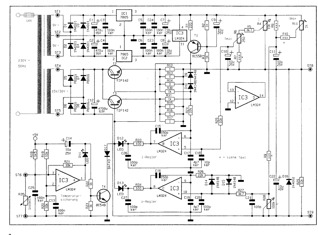
[/size]What's the voltage at C12?What's the voltage at C7?What's the voltage at C8?Have you chosen the right resistors from "Tabelle 2" ?Which resistors have you used as R30 / R31 ?


The voltage at across C12 is 43V
Voltage across C7 and C8 are 5V, giving me a 10V split supply for the op amp.


I have chosen the resistors from Table 2 based on the 30V/2A version and have checked that the values are correct. Just to make sure, do Germans use commas instead of periods for decimals? For instance, for R8 it says to use 6,8k. I am assuming that this equates to 6.8k but just wanted to make sure.


Before I wasted any more of someone's time, I went through with the schematic and highlighted each connection after ensuring that it was correct. I found 2 or so problems and corrected them. I am not absolutely, positively guaranteeing that there are no errors, but am pretty sure there is not. Here is the problem now. D12 is constantly lit, and the voltage adjustment no longer works. I can vary the voltage from -0.5v to -150mV . Turning the current adjust pots do not do anything except the trimpot(R6), when I bring it do the far end of its travel on one side it dims D12 to about half of what it was. What could cause this? A fried component, an incorrect setup,...??


The current source(R1,2,3; and the transistor) is sourcing ~8mA but I guess it is all being sunk through D12? Also, I traded out the TIP142's just to make sure that they weren't blown or anything.


Here is my somewhat vague understanding of the circuit. The current source supplies a constant current of ~8mA to the bases of the pass transistors. If/when the voltage or current needs regulating, the op-amp sinks some of this 8mA to itself, effectively 'stealing' the current from the transistors. I have a couple of (possibly silly/stupid) questions. I understand how to use a transistor as a current source(as used in this circuit), but I don't understand how the change in base current of the transistors can change the voltage. Also, how does the op amp know how much current is flowing, in order to regulate it. One more: Based on my(very limited) op amp knowledge, the op amp has to have some sort of feedback, otherwise a few nV difference between the 2 inputs would make it swing immediately to the respective power rail. How are the two op amps getting their feedback? Could someone recommend some reading material on the subjects. I could not find anything to help me understand these things.


Thanks so much,
Joshua


P.S. here is another copy of the schematic so you don't have to go to page 1 ;)


Online IanB

  • Super Contributor
  • ***
  • Posts: 11885
  • Country: us
Re: DIY Power Supply Build
« Reply #55 on: September 06, 2011, 01:14:08 am »
do Germans use commas instead of periods for decimals? For instance, for R8 it says to use 6,8k. I am assuming that this equates to 6.8k but just wanted to make sure
Yes. Most European countries use this convention, with the exception of the UK.
 

Offline Richard W.

  • Regular Contributor
  • *
  • Posts: 149
  • Country: de
Re: DIY Power Supply Build
« Reply #56 on: September 07, 2011, 09:04:42 am »
voltages and resistors seem to be okay.

Quote from: Joshua
Thanks for the reply. So D13 is on when I am in constant voltage mode. I can adjust the voltage all the way up from 0 - 30v and the light should be on regardless of load or no load. D12 is on when the current limiting has come into play. If I lower the current level with the pot, it should come on when I reach that value. I.E., if I connect a load that will pull 1A and I have my current limit set to 500mA, the supply will only allow 500mA to flow, and the led will light indicating that it is actually limiting current. Is all that right?  To clarify, is the current function constant current, or current limit? I mean, will the supply only cap the max amount of current allowed, or will it try and supply the designated current continuously and change the voltage to make that happen(within the limits of the supply)?

It is constant current, NOT just limit. The maximum voltage is the voltage which you have set with the voltage-pot.

Asumed you set the current to 500mA and the voltage to 5V:

with a 1Ohm resistor connected there is a current of 500mA and a voltage of 0,5V
with a 100 Ohm resistor conntected, there will be a current of 50mA at a voltage of 5V
« Last Edit: September 07, 2011, 09:06:25 am by Richard W. »
 

Offline JoshuaTopic starter

  • Regular Contributor
  • *
  • Posts: 194
  • Country: us
Re: DIY Power Supply Build
« Reply #57 on: September 08, 2011, 02:36:16 am »
voltages and resistors seem to be okay.

It is constant current, NOT just limit. The maximum voltage is the voltage which you have set with the voltage-pot.

Asumed you set the current to 500mA and the voltage to 5V:

with a 1Ohm resistor connected there is a current of 500mA and a voltage of 0,5V
with a 100 Ohm resistor conntected, there will be a current of 50mA at a voltage of 5V


Alright, but how do I tell it which mode I am want-constant voltage or constant current? Also, with the voltage set to 5V in constant voltage mode, can I limit the current to, say, 200mA? Same with constant current, can I set the current to 200mA and limit the voltage to,say, 3V? 


Online IanB

  • Super Contributor
  • ***
  • Posts: 11885
  • Country: us
Re: DIY Power Supply Build
« Reply #58 on: September 08, 2011, 02:45:35 am »
Alright, but how do I tell it which mode I am want-constant voltage or constant current? Also, with the voltage set to 5V in constant voltage mode, can I limit the current to, say, 200mA? Same with constant current, can I set the current to 200mA and limit the voltage to,say, 3V?
You don't really have a mode that you can select with a switch or anything like that. There is a limiting voltage and a limiting current. At any given point in time either the voltage limit is active or the current limit is active. It is not possible for any other situation to exist.

Basically what will happen is that if you turn up the voltage, the current will increase until either the current limit is reached or the voltage reaches the maximum setting.

On the other hand, if you turn up the current the voltage will increase until either the voltage limit is reached or the current reaches the maximum setting.

If you carefully think through the way this works (the way this must work), you will see that all eventualities are catered for.
 

Offline JoshuaTopic starter

  • Regular Contributor
  • *
  • Posts: 194
  • Country: us
Re: DIY Power Supply Build
« Reply #59 on: September 08, 2011, 03:15:53 am »
Alright, but how do I tell it which mode I am want-constant voltage or constant current? Also, with the voltage set to 5V in constant voltage mode, can I limit the current to, say, 200mA? Same with constant current, can I set the current to 200mA and limit the voltage to,say, 3V?
You don't really have a mode that you can select with a switch or anything like that. There is a limiting voltage and a limiting current. At any given point in time either the voltage limit is active or the current limit is active. It is not possible for any other situation to exist.

Basically what will happen is that if you turn up the voltage, the current will increase until either the current limit is reached or the voltage reaches the maximum setting.

On the other hand, if you turn up the current the voltage will increase until either the voltage limit is reached or the current reaches the maximum setting.

If you carefully think through the way this works (the way this must work), you will see that all eventualities are catered for.


Awesome! That makes sense. Thank you for the great explanation.  ;D


Now back to seeing what is wrong with my circuit. Might be a day or so though, got to go to a funeral tomorrow so probably no more progress tomorrow. I'm getting really excited/anxious because I really want to move to the 'fun' stuff, like playing around with a working circuit and trying to improve it, not troubleshoot. (I know, I know, I learn so much more from troubleshooting. Don't get me wrong, I love this stuff, but some stuff just seams more 'appetizing'  ;) ) Also, I've got some other projects in the pipeline, but there's no way I can probably do them without some sort of variable supply.


Somewhat unrelated, whats the protocol on this circuit I'm using. What I mean, is that this circuit, from what I gather, is from a kit(?) by ELV in germany. If I take this circuit as a base, and slightly modify it to fit me a little better, can I then release all of the design files/mechanical case drawings, etc... and it be true 'open hardware'? I am definitely doing all of my projects as open hardware so I just wanted to know what the technicalities were.


Joshua
 

Offline JoshuaTopic starter

  • Regular Contributor
  • *
  • Posts: 194
  • Country: us
Re: DIY Power Supply Build
« Reply #60 on: September 19, 2011, 03:34:55 am »
Okay, so I think I've got it working on the breadboard, but now have to order some higher wattage resistors.

Anyway I have a question: This power supply is made to built in two configurations: 15V 4A or 30V 2A.
My original plan was to mod the circuit to do 30v 4A. Note: I will be building two identical versions to have a dual supply.

That means that I can either have one of these three setups. The first two are the one specified in the circuit.

   I. 15V 8A parallel or 30V 4A series

   II. 30V 4A Parallel or 60V 2A

   III. 30V 8A parallel or 60V 4A

I am leaning toward one of the first two right now. It just seems like it would be too difficult for me right now with all of the high power design, and heat sink design, etc.... Anyway, my question to you is, which one would you build? In other words, what do/would you use more often?

I've added a poll.

Joshua
« Last Edit: September 19, 2011, 03:39:17 am by Joshua »
 

Offline Lawsen

  • Frequent Contributor
  • **
  • Posts: 253
  • Country: us
Re: DIY Power Supply Build
« Reply #61 on: September 19, 2011, 04:57:50 am »
I would use the Bourns potentiometers to adjust voltage and current. 

http://www.bourns.com/ProductFamily.aspx?name=potentiometers

Toroidal power transformers are usually very compact, efficient transfer of energy between input primary winding to the output secondary winding and the magnetic flux is confined to the center of the core, "doughnut hole."  I have seen expensive stereo amplifier with the French "Atoll" brand uses these toroidal power transformers. 

http://www.tabtronics.com/TECHNOLOGY/ElectromagneticBasics/ToroidalTransformerBasics/tabid/112/Default.aspx#the_toroidal_core

I have built a non adjustable linear, regulated power supply in my experience.  Reading your project is exciting.  Are you going to etch your own printed circuit with wide traces for lots of current? 
« Last Edit: September 19, 2011, 05:00:56 am by Lawsen »
 

Offline Lanman

  • Contributor
  • Posts: 19
  • Country: us
Re: DIY Power Supply Build
« Reply #62 on: September 20, 2011, 12:25:30 am »
Great project Joshua.  It's been interesting following your progress.   

Dave
 

Offline mrflibble

  • Super Contributor
  • ***
  • Posts: 2051
  • Country: nl
Re: DIY Power Supply Build
« Reply #63 on: February 08, 2014, 09:23:10 am »
This is an interesting design, looks like fun to try! I went over the schematics yesterday, and I think I more or less understand it. Except for one thing.

I take it D9 & D10 are meant as protection against fast transients on the load? But it looks like in the current configuration it's not going to do very much. Either that, or I am missing something. :-//

Shouldn't the cathode of D9 be connected to ST8 (low side of the 1 Ohm sense resistors)? That would clamp the sense voltage across the resistors to about 2 diode drops, which would correspond to about 4.2 A per transistor.

Any ideas?
 

Offline jkf1000

  • Regular Contributor
  • *
  • Posts: 78
  • Country: england
Re: DIY Power Supply Build
« Reply #64 on: April 20, 2014, 09:59:30 am »
Hi all, first time post on the forum but wanted to add my bit, I found this circuit from a google search and am very impressed by it, I found this thread when the first build was almost complete, really interesting reading. I didn't bother breadboarding, but instead went first to veroboarding. Worked first time out, which was a suprise given a few changes I implemented. Firstly a full wave bridge rectifier was used after the secondary, much easier to cool, and instead of the recommended 3X 1ohm emitter resistors I used single 0.22ohm 5 watt ceramics, not sure if the 0.11ohm change makes a significant difference or not to the current sensing but seems to work fine.

I am still undecided which final range to use, so the resistors used to set the range for either the 30v or 15v variant have been mounted on vero pins so if I decide to just use the vero built version, I can easily change the options around without lifting the board. My recycled transformer has secondary taps for 32v or 16v, so I have the option to change if I need to, my primary concern is the heat generated by the output transistors running a moderate load at lower voltages, say from 3.3v to 12 volt range. That is a significant voltage drop/dissipation accross the pass transistors.

Next up is a case design, but initial impressions of the circuit into my adjustable load are very promising, I will try and post some pictures as my project progresses..
Karl


Share me

Digg  Facebook  SlashDot  Delicious  Technorati  Twitter  Google  Yahoo
Smf