Hi tggzzz,
I saw your conversations with one of my colleagues. Please allow me to clarify a few things to avoid further confusion and misunderstanding.
- “Residual Resistance” is not an appropriate term to describe our product, mainly because we consider “Residual Resistance” as part of our output circuit. Unlike traditional resistance boxes, we measure and record this residual value in advance and compensate for this value accordingly when outputting the resistance.
Sorry, but that is a false statement. You do consider "residual resistance" appropriate, and you claim it is a defining advantage over your competitors' well-establised products. See your kickstarter page here...
- If you would like to know this value, it is about 0.5 Ω. And FYI, since we also include an extra 0.5 Ω resistance in our output, this makes the minimum output range of our resistor 1 Ω. We have clearly specified this number in our spec. Say, if a client needs a 10-Ω output, our resistance will first produce a 9-Ω. With the 1-Ω extra "residual resistance"", the end output will be exactly 10-Ω
That's fine. But it doesn't match the terms used in your publicity.
- We have no intention to hide any information or mislead others, but we just don’t think the term “Residual Resistance” applies to our product. Moreover, the end user does not have to pay attention to this value. However, we can explain this when needed.
- Moreover, we are not the first one adopting this idea. In fact, IET implements the same idea in their resistance boxes: https://www.ietlabs.com/os-260-resistance-decade-box-rtd-simulator.html. On their website, they clearly state: "Automatic Eliminates Residual Resistance - the OS-260 residual resistance is automatically factored out in output resistance value."
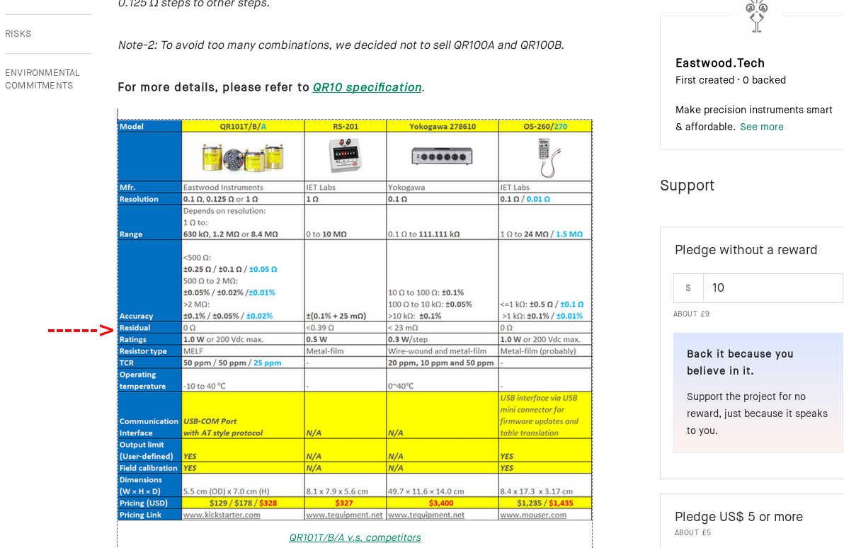
Now look at the information in your publicity (above). The IET-201 claims 0-10Mohm, residual 0.39ohm. The Yokagawa 278610 claims 0.1-111.111kohm, residual 0.023ohm.
Do you claim that just because some people/companies use a term, that use of the term becomes correct?
If you do claim that, then presumably you think it is correct to measure time in Siemens (i.e. conductance). Look at how many companies/people incorrectly specify times in "nS" or "mS"! That mistake can be made through ignorance or carelessness. I hope you aspire to avoid looking ignorant or careless!
Hi tggzzzzzz,
Good day! 
Just one question, to be simplified, if for a resistance box claimed to be ±0.01% of RD:
1. You set 1.0 Ohm, then it can "tell you" the output is 1.0 Ohm , and you measured it is 1.0 ±0.01% of RD.
2. Moreover, not only for the point 1.0 Ohm, but it can be applied in the whole range "1.0 Ohm - 1.2M Ohm". i.e.
You set n Ohm, then it can "tell you" the output is n Ohm , and you measured it is n ±0.01% of RD.
Then would you mind to tell us what's the "residual resistance" of such a resistance box in your understanding?
Best,
CC
1) What is "RD"?[1]
2) I'm not making claims about a device's performance, so I don't have anything to justify.
3) Stop trying to avoid the points I've made about your claims[2] .
[1] Abbreviations and acronyms should be avoided or introduced, e.g. "Relative Density (RD)". That also applies to another acronym you have used: Photovoltaic (PV)
[2] Your customers will notice. People that might think of investing in your kickstarter will notice. Various TV programmes (e.g. Dragon's Den in the UK) illustrate that potential investors rapidly say "I'm out" (i.e. won't invest) when they feel people trying to get investment are avoiding answering their questions.
For the avoidance of doubt, I can believe that your device might sell. But if you oversell its performance, you might have devices returned.
Hi tggzzz,
Sorry for my straight forward, I though you must be an expert who has rich experience. O.K. Let me explain:
1) RD is short for Reading, like FS (Full Scale), they 're frequently used Abbreviations to describe the accuracy of an instrument in different angle of view. (FS makes the tolerance value looks "better" in general)
2) (I really don't now how to make a comment of your words)
3) We have tried and tried and tried our best to explain our understanding and the mechanism of why we can say our resistance box have ZERO residual resistance. However, in return you just saying we are "trying to avoid your point"?! ARE YOU SERIOUS?
BTW, Abbreviations for PV is not what you have guessed. If you have read our datasheet or user manual, you probably already know. PV is short for "Process Value" and it's a concept borrowed from automatic control field.
And thanks for your kindly reminding (seriously), yes anyone can return the product if it's oversold. Trust me, we also hate such products.
“The IET-201 claims 0-10Mohm, residual 0.39ohm. The Yokagawa 278610 claims 0.1-111.111kohm, residual 0.023ohm.”
— Is there any problem if we claim 1-1.2 MOhm, and residual is 0? And how can you explain IET says "the OS-260 residual resistance is automatically factored out in output resistance value". Since according to your theory, how can "residual resistance" be factored out? It's always there, correct? And, if something be factored out, can we just say it's ZERO?
We just see things in different angle of view, it's nothing about right or wrong and even “honest” or "dishonest".
If residual resistance is transparent to user, why we have to mention it and say it's 0.5 Ω to let people do meaningless calculation (-0.5 then +0.5, what for???)? I'd like to address it again: For conventional resistance box they have to mark residual resistance is because they cannot find a way to make compensation for it; while for QR10, it's not a problem at all.
BR(@tggzzz BR is short for "Best Regards"),
CC


