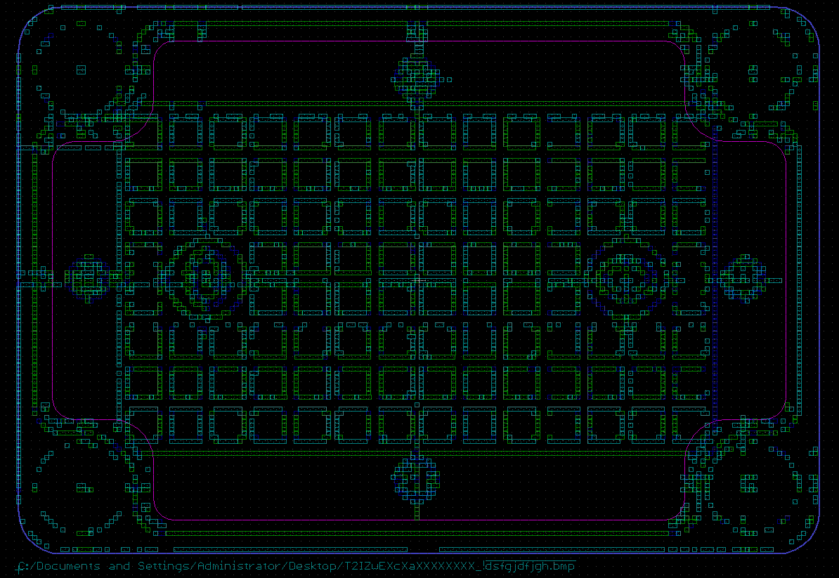
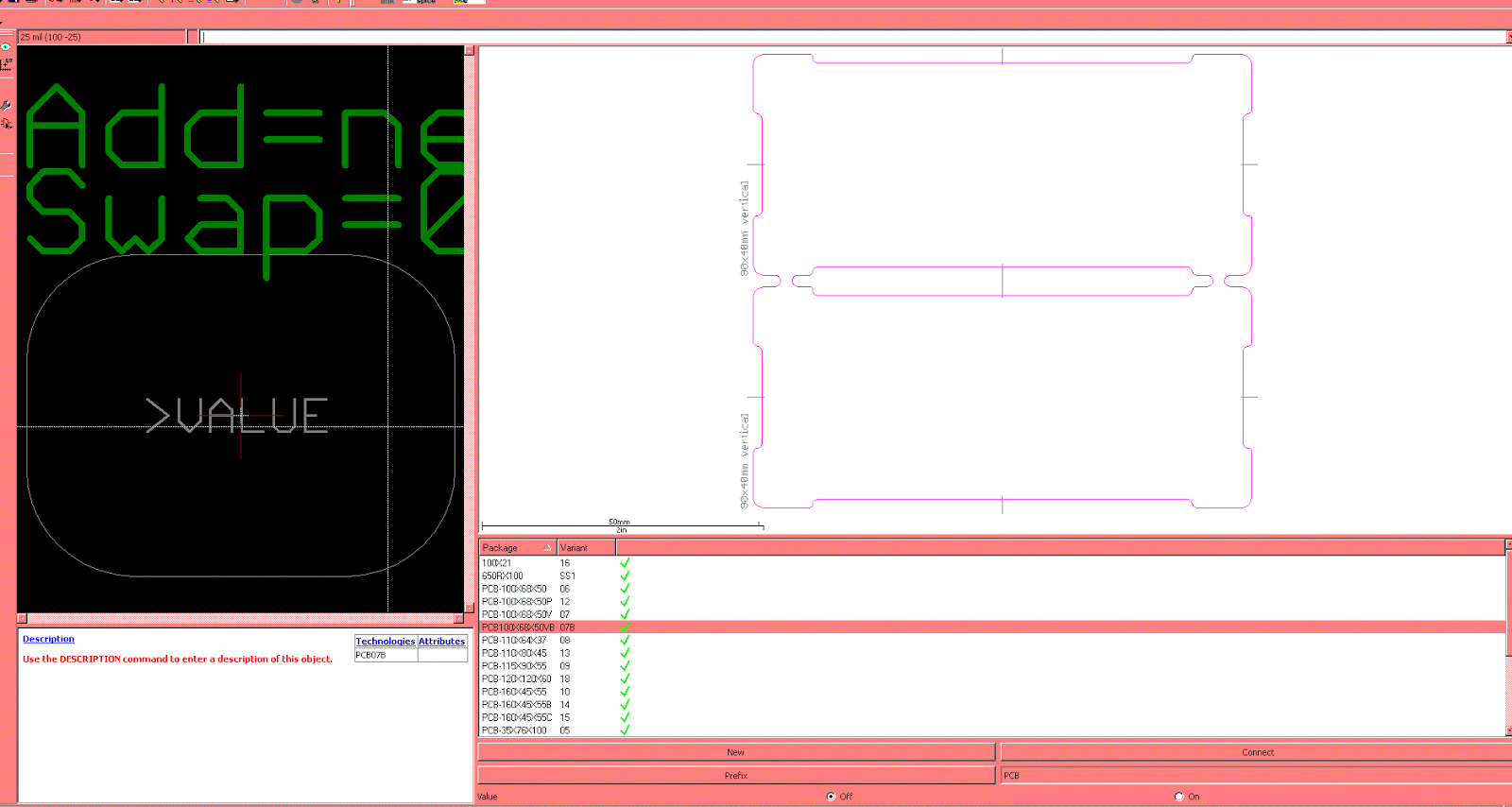
I wish to share this non standard item creation, it is kind of a productivity aid if you are using a fixed few types of boxes to do your DIY projects
example box
https://item.taobao.com/item.htm?&id=18128666680 (find a retailer that shows a good plan view)

import into gimp 2.4.7 (compatible with windows BMP format)
tools – transform – crop
image – print size – change size/dimensions to coincide with actual box size (note final DPI = 53.210)

image – mode – select indexed color – select max color = 4 to 8 (lesser colors = lesser accuracy but less clutter)
save as – bmp

eagle – ULP – insert bmp
scan used colors (option to reduce colors further)
format = select DPI
scale = final DPI of BMP image (in this case = 53.210)

run script - rough shape of box will appear
draw appropriate outlines using eagle layers. ie : primary outline of PCB, drill holes, guides and exclusions.

select BMP layers (layer 200-233?) to delete BMP guides/shapes insert eagle labels. now we are left with just your PCB cutting shapes.
save as PCB template
make other templates sized according to box limits

when components are laid together, the enclosure template allows user to have better gauge of what to do with PCB/box/component in the final window laying out parts. ie : the SMA needs a deeper cutout into the PCB (or a very large hole?) or the potentionmeter can fit well when bolted to case.

it would be interesting if someone makes a KiCad version of this template "tip"