Author Topic: PCB Led board layout for my new bigger UV-LED-box  (Read 7752 times)

0 Members and 1 Guest are viewing this topic.

Offline ArpTopic starter

  • Supporter
  • ****
  • Posts: 107
  • Country: se
    • Henriks bits n pieces
PCB Led board layout for my new bigger UV-LED-box
« on: August 17, 2013, 08:40:37 pm »
Etched and drilled a PCB for my new bigger UV-led box. Drilling all those holes was quite tedious, and since I need a few more boards I thought I'd let a PCB manufacturer do them. It will be both cheaper, better and take less time obviously :o.

This is my design so far. Measurements are 160 mm x 100 mm. I'm thinking of daisy-chaining them. Hopefully there are enought details to make sense of. The top is a ground plane and the bottom is the power plane. Any input would be greatly appreciated  :)
 

Offline mrflibble

  • Super Contributor
  • ***
  • Posts: 2051
  • Country: nl
Re: PCB Led board layout for my new bigger UV-LED-box
« Reply #1 on: August 17, 2013, 08:49:26 pm »
What kind of heat dissipation per your-favorite-area-unit do you have?
 

Offline chrome

  • Regular Contributor
  • *
  • Posts: 185
  • Country: be
Re: PCB Led board layout for my new bigger UV-LED-box
« Reply #2 on: August 17, 2013, 09:06:04 pm »
Why not make it 10x10cm and get 10 from seeed?

Then you can make a 3*3 panel (30x30cm) which will fit an A4 size PCB.

That's what I did, also if you leave the top silkscreen off and get tinplating (which is standard on seed I think) then it's a nice reflective surface, it's what I did anyway.

My PCB has interconnects on all sides and an actual connection for wires, it also has 9 led's per panel for other color lights that can be used to align stuff.
 

Offline ArpTopic starter

  • Supporter
  • ****
  • Posts: 107
  • Country: se
    • Henriks bits n pieces
Re: PCB Led board layout for my new bigger UV-LED-box
« Reply #3 on: August 17, 2013, 09:09:09 pm »
What kind of heat dissipation per your-favorite-area-unit do you have?

Pretty nooby when it comes to this, but meaning I should incorporate "exposed-copper heat-sinking" or how it's called?

They are 20mA 3.4V leds. Not sure if they get so hot during that short period of exposure time. But could be a good idea for the long-term effects. If I understood correctly? :D


Offline ArpTopic starter

  • Supporter
  • ****
  • Posts: 107
  • Country: se
    • Henriks bits n pieces
Re: PCB Led board layout for my new bigger UV-LED-box
« Reply #4 on: August 17, 2013, 09:29:41 pm »
Why not make it 10x10cm and get 10 from seeed?

Then you can make a 3*3 panel (30x30cm) which will fit an A4 size PCB.

That's what I did, also if you leave the top silkscreen off and get tinplating (which is standard on seed I think) then it's a nice reflective surface, it's what I did anyway.

My PCB has interconnects on all sides and an actual connection for wires, it also has 9 led's per panel for other color lights that can be used to align stuff.

Thanks for the input :-+

Leaving the solder-mask off on top sounds like a pretty good idea.

Thought I'd go for this dimension cause I have already completed a board, but maybe it would be better with something square-shaped. I think I'll do that, and not be so lazy :)

I got a quota from a Chinese manufacturer. $55 inc. shipping for 10pcs 160x100. Pretty shocking as I buy a single photoresist card for $6 a piece :o.
 

Offline notsob

  • Frequent Contributor
  • **
  • Posts: 696
  • Country: au
Re: PCB Led board layout for my new bigger UV-LED-box
« Reply #5 on: August 17, 2013, 09:42:33 pm »
Have a look at this guys reflectuve UVLED pcbs - all interconnected

http://en.elektronicastynus.be/projects/81/
 

Offline chrome

  • Regular Contributor
  • *
  • Posts: 185
  • Country: be
Re: PCB Led board layout for my new bigger UV-LED-box
« Reply #6 on: August 17, 2013, 10:09:49 pm »
Why not make it 10x10cm and get 10 from seeed?

Then you can make a 3*3 panel (30x30cm) which will fit an A4 size PCB.

That's what I did, also if you leave the top silkscreen off and get tinplating (which is standard on seed I think) then it's a nice reflective surface, it's what I did anyway.

My PCB has interconnects on all sides and an actual connection for wires, it also has 9 led's per panel for other color lights that can be used to align stuff.

Thanks for the input :-+

Leaving the solder-mask off on top sounds like a pretty good idea.

Thought I'd go for this dimension cause I have already completed a board, but maybe it would be better with something square-shaped. I think I'll do that, and not be so lazy :)

I got a quota from a Chinese manufacturer. $55 inc. shipping for 10pcs 160x100. Pretty shocking as I buy a single photoresist card for $6 a piece :o.


You can get my Gerbers if you want.

It does use 15V though instead of 12V
 

Offline mrflibble

  • Super Contributor
  • ***
  • Posts: 2051
  • Country: nl
Re: PCB Led board layout for my new bigger UV-LED-box
« Reply #7 on: August 17, 2013, 10:35:40 pm »
I got a quota from a Chinese manufacturer. $55 inc. shipping for 10pcs 160x100. Pretty shocking as I buy a single photoresist card for $6 a piece :o.

If you shop around you can probably get it cheaper. Quick check at itead ...
http://imall.iteadstudio.com/open-pcb/pcb-prototyping/im120418010.html

10 pcs 150x100 for $48. Although maybe your $55 quote includes better shipping options.

And looks like dissipation shouldn't be too much of an issue with that kind of led power.
 

Offline sleemanj

  • Super Contributor
  • ***
  • Posts: 3024
  • Country: nz
  • Professional tightwad.
    • The electronics hobby components I sell.
Re: PCB Led board layout for my new bigger UV-LED-box
« Reply #8 on: August 18, 2013, 12:10:53 am »
Etched and drilled a PCB for my new bigger UV-led box.

I made a couple quite similar at 10x17cm a few weeks ago as it happens. I put m/f connectors (just right angle 2.54mm headers) on all 4 sides so boards can be directly plugged together horizontally or vertically and just apply power to one of the boards (in other words they can seamlessly tessellate in any direction).

I also "wove" a few visible (red in my case, because I have heaps) 1206 leds and limiting resistors on the top surface with a  separate power bus so I can switch between the 5mm UV for exposing and the 1206 visible for checking artwork etc.  Again the power bus connectors are on all 4 sides to allow for plugging boards together.  Since I left it bare copper I used curvy traces on the top side for aesthetics as they wandered there way through the ground fill and visible leds "forest".

They work well, but I'm glad I don't do big boards, since soldering in all those LEDs was... tedious.


Bad pictures attached, as you can see I have them "mounted" at the bottom of a tall cardboard tube, on top of which I place my glass-clamped pcb+artwork, so anyway, taking pictures down a black hole is harder than it seems.  Thing to note is the join between the two boards does not result in a double-row of leds as it looks like yours would, see how on your design the top side and bottom side have the same LED stagger, as do the left and right sides - when you join your boards together you'll get a double row and thus uneven light distribution at the join. 
« Last Edit: August 18, 2013, 01:17:16 am by sleemanj »
~~~
EEVBlog Members - get yourself 10% discount off all my electronic components for sale just use the Buy Direct links and use Coupon Code "eevblog" during checkout.  Shipping from New Zealand, international orders welcome :-)
 

Online mariush

  • Super Contributor
  • ***
  • Posts: 5026
  • Country: ro
  • .
Re: PCB Led board layout for my new bigger UV-LED-box
« Reply #9 on: August 18, 2013, 12:36:38 am »
Arp, this seems like the job for some of these boards :

http://uk.farnell.com/roth-elektronik/re310-s1/labor-card-cem3-3holepads/dp/1837352


160x100, seems perfect to put the leds evenly spread out, with a row reserved for voltage from place to place, resistors easy to solder between strips or just using axial resistors..

http://uk.farnell.com/roth-elektronik/re315-lf/pcb-eurocard-fr4-2-54mm/dp/1172142

This would be probably suited for several leds in series with a single resistor after  .. .see board2 attached

http://uk.farnell.com/roth-elektronik/re330-lf/labor-card-fr4-rm-2-54-mm/dp/1837356

This would also work just like first link ... but you get less usable space (not the full 160mm)

« Last Edit: August 18, 2013, 12:42:37 am by mariush »
 

Offline mrflibble

  • Super Contributor
  • ***
  • Posts: 2051
  • Country: nl
Re: PCB Led board layout for my new bigger UV-LED-box
« Reply #10 on: August 18, 2013, 02:26:13 pm »
Seems to me those boards from Roth Electronik are a more expensive solution than getting ready made PCBs. That and more work than PCBs as well.

Regarding PCBs and thermal management, you might find these two app notes interesting:

http://www.avagotech.com/docs/AV02-0955EN
http://www.avagotech.com/docs/AV02-1958EN
 

Online mariush

  • Super Contributor
  • ***
  • Posts: 5026
  • Country: ro
  • .
Re: PCB Led board layout for my new bigger UV-LED-box
« Reply #11 on: August 18, 2013, 04:00:36 pm »
I kinda disagree with the more work part.

I guess it depends if you already have the chemicals to etch boards or solder paste and oven/some heating solution to solder surface mount resistors.
Or if you have the patience to wait a couple of weeks to get some custom pcbs made.

I'm looking at sleemanj's pictures and I can't see myself soldering those smt resistors on the pcb, I'd waste a lot of time doing it manually and I'd get bored with it.

In contrast, I'd just use one of those 
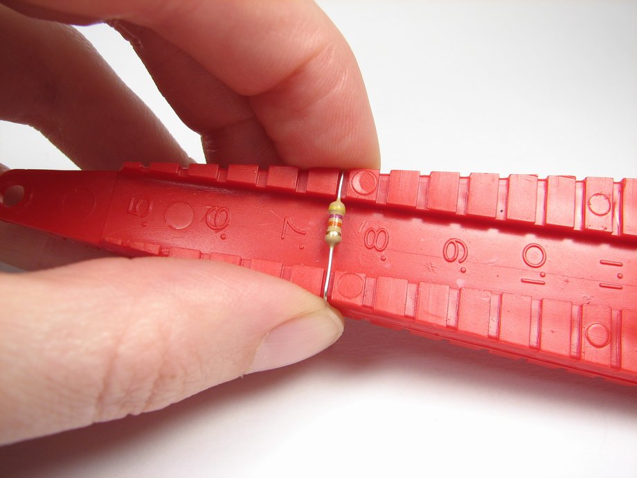
plastic lead former tools to just prepare some 1/8w resistors in advance to the same lead size, stick the leds in the holes evenly spaced, flip the pcb and start soldering.  And I can use the leads I cut from resistor to make jumpers between two 3-hole pads and form power buses where needed.  Or I can just get some solid core network cable, strip the insulation and solder the wire across the pads i want to connect together on the other side. Super fast and easy.

And in the case of first proto board pictured in my previous post, being symmetrical on all sides and covering the whole 160x100mm, it would be easy to connect them together with straight or 90 degree 0.1" connectors.

5 pounds, 7.5 dollars... it's a bit expensive. As mrflibble says, you can get 10 pcs 150x100 for $48, it would cost you 75$ for 10 such protoboards, about 80$ with shipping.. but I can get them to my door in 2 days while i'd wait three-four weeks for itead.
But you don't have to buy them from farnell, you should find the model with a bit of search on ebay.

lead forming tool mentioned:


Offline ArpTopic starter

  • Supporter
  • ****
  • Posts: 107
  • Country: se
    • Henriks bits n pieces
Re: PCB Led board layout for my new bigger UV-LED-box
« Reply #12 on: August 18, 2013, 04:58:10 pm »
I have done two cards with veroboards. Wiring was extremely time consuming. Perhaps I could have done it faster with a better layout.  Took me many hours to finish them :o

My etched board was a piece of cake, excluding the drilling part. Soldering ~50 SMT resistors with a stereoscope, solder paste and a good soldering iron took only a few minutes.
« Last Edit: August 18, 2013, 05:07:02 pm by Arp »
 

Offline ArpTopic starter

  • Supporter
  • ****
  • Posts: 107
  • Country: se
    • Henriks bits n pieces
Re: PCB Led board layout for my new bigger UV-LED-box
« Reply #13 on: September 16, 2013, 08:05:27 pm »
Received the PCB from circuit-mart.com today. All in all the cost of the boards was roughly $75 for 20 pcs 10cm^2, and that included express shipping. I had them in under a week.

Had but to try one, and they seem to work pretty good. Have yet to check the entire batch

Thanks for all the input guys :-+

« Last Edit: September 16, 2013, 08:58:37 pm by Arp »
 

Offline matizen

  • Newbie
  • Posts: 1
  • Country: gb
Re: PCB Led board layout for my new bigger UV-LED-box
« Reply #14 on: May 17, 2023, 05:37:41 pm »
Hi

I am building an experimental luminaire and would really appreciate the gerbers for these PCBs - could you please kindly share?

Thank you in advance!!


Share me

Digg  Facebook  SlashDot  Delicious  Technorati  Twitter  Google  Yahoo
Smf