Hi group,
I promised an update after I have tested the prototype.
I received the partially assembled board assemblies from JLCPCB. This is the first time that I have ordered assembled boards. The process was very smooth. I chose only to have them install parts in their
basic library. You can have them install other parts, but there is a $3.00 per line item charge.

Here is a picture of the assembled board.
SchematicThis is the revised schematic:
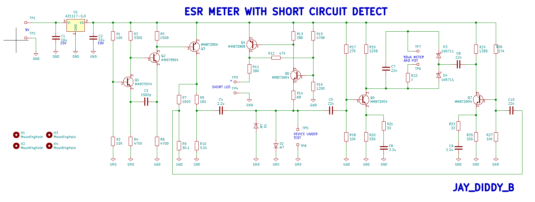
The changes are:
1) The regulator was changed from the 7805 to AZ1117-5. This has a lower dropout voltage, but requires larger capacitors.
2) C4 was added. This is a d.c. blocking capacitor to allow shorted capacitors to be detected.
3) The circuitry Q4 and Q5 was added. The LED will illuminate if the capacitor being tested is less than 25

.
The rest of the circuit is the same as the original version.
Notes: This was redrawn in KICAD version 5.00 there is no connection between the component references in this version and the previous version or the LTspice model.
R22 must be chosen depending on the resistance of the 50uA meter movement. In my case the resistor is around 18k
If you search 5 transistor ESR meter on the internet you get quite a few hits from all around the world. A lot of people have done the right thing and given credit back to the original design presented in this thread. Other people have not. It would be nice if you make a copy or a derivative to credit the original work.
FilesI have attached a zipfile that should contain enough information to open the project in KICAD. Let me know if anything is missing.
I have also attached the LTspice model.
Regards,
Jay_Diddy_B
 picture.PNG
 (1753.64 kB. 1196x903 - viewed 5215 times.)
7 transistor ESR meter with sc detector.asc (7.7 kB - downloaded 471 times.)


