TL;DR: Does the USB CDC protocol support flow control (specifically, the MCU says "hold up", and any writes on the connected PC block)? How does the MCU say "hold up"?
I just ran the USB CDC demo for my LPC Expresso LPC11U37H (an ARM cortex M0+ board fwiw), and I tested what happens when the UART's buffers fill up by adding long sleeps in my application code to simulate a complex operation. Perhaps I was expecting too much, but I was expecting the USB interrupt handlers to notice if the buffers were getting near full, and for them to tell the PC to hold up. Alas, the code I see is vastly simpler; in fact there's no ring buffer to speak of at all, and bytes are dropped.
So, as written above, is what I'm trying to do here even possible with the standard USB CDC protocol? Which endpoint should the "hold up" command be sent along, and what should it look like? Not looking for the complete answer, just some basic pointers would be greatly appreciated!
EDIT: Here's a more concrete version of my question:
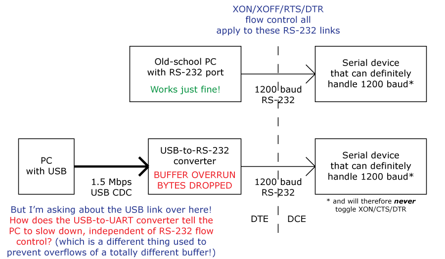
In this hypothetical situation, we have a 1200 baud device that is fast enough to handle whatever a PC throws at it, because the 1200 baud channel is naturally quite limited, and the device can hypothetically handle each line/character as it comes. This means that the RS-232 device here is guaranteed to never require any form of RS-232 flow control. However, once you introduce a USB CDC-based USB-to-UART converter, there is the possibility that the PC could overrun the buffer
in the USB-to-UART converter; which means that this system can now drop bytes. What I'm asking is, how is
this problem handled/prevented? Or is the genuinely a thing that cannot be avoided?
SOLUTION: My LPC should not be echoing USB ACKs for packets that it can't accommodate in its buffer. The PC will retransmit these packets, so the data is not dropped. Actually
implementing this is left as an exercise to the reader (read: I haven't got this working myself yet).
EDIT: Fixed broken image link.


