Author Topic: Help with Opamp's  (Read 1345 times)

0 Members and 1 Guest are viewing this topic.

Offline zx81vgaTopic starter

  • Newbie
  • Posts: 3
  • Country: de
    • Werner's Propeller Page
Help with Opamp's
« on: July 15, 2021, 05:35:39 pm »
Hello Forum,

i’m 58 Years old and live in Nürnberg, Germany and a huge Fan of the EEV-Blog.

I’m a Digital-Fanboy since 1985 and not so Analog.  :(

I made some Projects with the Propeller-Chip (P8X32A).
I created a Virtual-Tape for the ZX81 with the Propeller-Chip (SD-Card, 20x4 LCD, Buttons).

So the Load works well, now i want to Save ZX81 Programs to my Device.

Here ist the Problem, the MIC-Output from the ZX81 has very low Output, see the Red Signal in the Picture below:


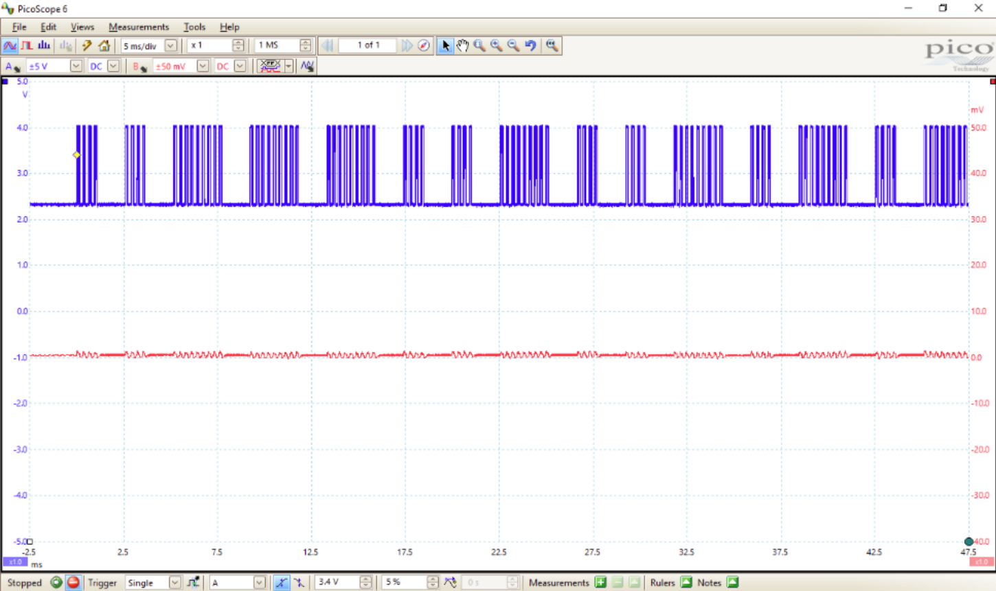
think it’s 1-2 mV PP.

I want to amplify the Voltage to get 5 V Pulses.

I know i need an OpAmp Stage or more.

Is this possible to get the 4/9 Pulses to feed an 74LS14 to TTL-Level?

Clueless about OpAmps. :P

Which OpAmp(s) should i use, a Schematic is also helpfull.

Only 5-12 V are available. (No negative Voltage)

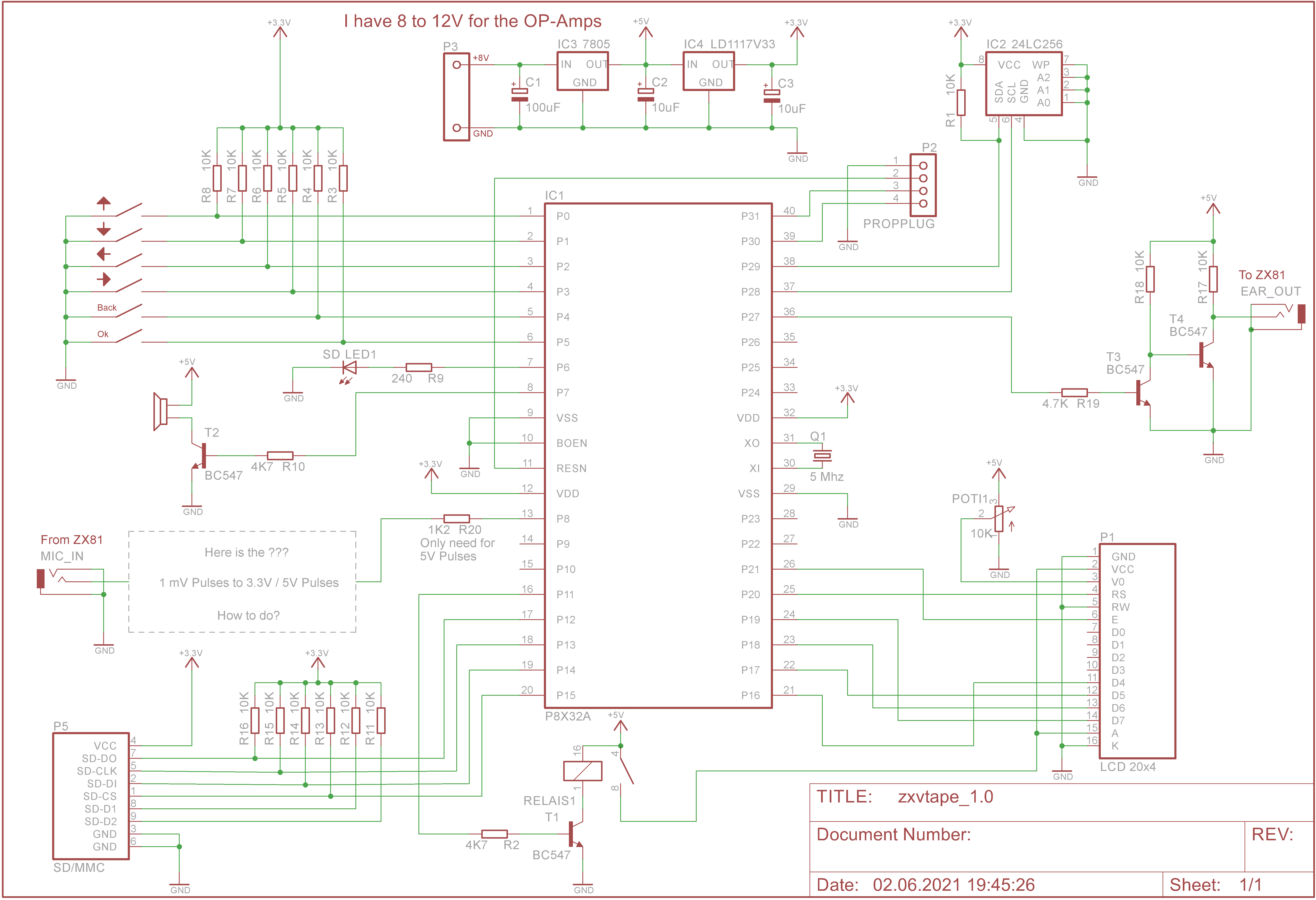
Here a Schematic of ZXVTAPE:


Thanks for the help.

Werner
« Last Edit: July 15, 2021, 08:30:48 pm by zx81vga »
 

Offline RoGeorge

  • Super Contributor
  • ***
  • Posts: 6185
  • Country: ro
Re: Help with Opamp's
« Reply #1 on: July 15, 2021, 06:20:21 pm »
Welcome!   :)
I had a ZX81, too, a few decades ago, it was a lot of fun!

Totally forgot about the MIC signal that is an output to save the programs on a cassette tape recorder, and the signal is very low, indeed.  By this schematic here https://retrocomputing.stackexchange.com/questions/20002/why-does-the-zx81-not-have-user-definable-characters-without-extra-hardware-i-e the divider for audio out is about 1/1000, so it is expected to be at most 5mVpp.

There are plenty of OpAmps that can work at 5V or even lower, and there's no need for a negative voltage to feed them, for example LM358.

Search for "LM358 microphone amplifier" and build one powered between +5V and GND.  For example, this is one returned first at a search, seems OK.


Use +5V for Vcc and copy everything between R1 and C3 exclusive.  You do not need the R1 because that is just to power the electret microphone drawn in the schematic, and you don't need C3 because the digital input from the propeller is between 0 and +5V.  Put the C2 as close as possible to the power pins of the LM358, eventually solder it piggybacking the capsule of the LM358.  The ratio of R5/R4 gives the amplification, here 100.  You can increase the R5 to 1M in case that the signal is still too small.

I didn't tried that schematic, but it looks like it should work.

I have a propeller, too, but I don't remember the model and if there were any analog pins.  Does your propeller has any ADC analog input pins?

Offline capt bullshot

  • Super Contributor
  • ***
  • Posts: 3033
  • Country: de
    • Mostly useless stuff, but nice to have: wunderkis.de
Re: Help with Opamp's
« Reply #2 on: July 15, 2021, 06:32:54 pm »
Welcome!

In your context, an often used "trick" is the unbuffered inverter (74HCU04):

From the datasheet:
https://assets.nexperia.com/documents/data-sheet/74HCU04.pdf
look for linear amplifier, you should find this:


Most probably you'd need more than one stage, just cascade two or three of them.
For the component values, use something in this ballpark: C: 100n, R1: 10k, R2: 1M
Make two or three identical stages, connect them in series and add one or two of the remaining inverters after the last stage. The "linear" stages amplify the mV pulses by maybe 10 per stage, and the final inverter stages should make nice squares waves of the amplified pulses.
The linear amplifier trick works with these unbuffered inverters, not with the regular ones.

« Last Edit: July 15, 2021, 06:34:42 pm by capt bullshot »
Safety devices hinder evolution
 

Offline zx81vgaTopic starter

  • Newbie
  • Posts: 3
  • Country: de
    • Werner's Propeller Page
Re: Help with Opamp's
« Reply #3 on: July 15, 2021, 06:38:21 pm »
@RoGeorge

Thanks for your fast Answer.,

The Propeller 1 has only 32 Digital IO's.
The Propeller 1  run with 3.3 V Supply.

The Propeller 2 is a future Project.  ;D

I think 100 Amplification is not enough?

But i give it a Try...

Thanks

Werner
 

Offline zx81vgaTopic starter

  • Newbie
  • Posts: 3
  • Country: de
    • Werner's Propeller Page
Re: Help with Opamp's
« Reply #4 on: July 15, 2021, 06:49:15 pm »
@capt bullshot

Thanks for your Reply,

i never heard of "unbuffered inverter's",
maybe this is my Solution...

Many Thanks

Werner
 

Offline RoGeorge

  • Super Contributor
  • ***
  • Posts: 6185
  • Country: ro
Re: Help with Opamp's
« Reply #5 on: July 16, 2021, 04:46:21 am »
I think 100 Amplification is not enough?

!!!  If the Propeller chip runs at 3.3V, then power the LM358 at 3.3V (Use Vcc = 3.3V for the OpAmp, and not 5V like I said the first time - I was saying 5V only because I didn't remember Propeller was working with 3.3V).  I don't know if Propeller 1 is 5V tolerant.  In case 3.3V is too little for the opamp you can use 5V and put a series resistor of 1k ... 10kOhm at the input pin of the propeller, the pin that is reading the audio from LM358.  !!!

Depending on the amplitude of the MIC output signal, with A = 100 it might work, or it might not work.
That is why the suggestion to increase the R5 value from 100 kiloOhm to 1 MegaOhm.

Online Zero999

  • Super Contributor
  • ***
  • Posts: 19491
  • Country: gb
  • 0999
Re: Help with Opamp's
« Reply #6 on: July 16, 2021, 09:35:41 am »
The LM358 doesn't have a rail-to-rail output, so when run off 3.3V, the maximum output voltage will be <1.8V.  The solution is to run if off 5V, or use an op-amp, with a rail-to-rail output, such as the MCP602. If you do go for the LM358, run off 5V, it's a good idea to add a 100R current limiting resistor between its output and the ADC input, to limit the current through the internal ESD suppression didoes, if it does output any voltages above 3.3V.
 

Offline RoGeorge

  • Super Contributor
  • ***
  • Posts: 6185
  • Country: ro
Re: Help with Opamp's
« Reply #7 on: July 17, 2021, 08:46:42 am »
I think a LM358 should still work, and if it doesn't work reliable then a pull-up resistor should fix that.
Though, a rail-to-rail output op-amp, like MCP602 or alike, would be preferable indeed.

Online Zero999

  • Super Contributor
  • ***
  • Posts: 19491
  • Country: gb
  • 0999
Re: Help with Opamp's
« Reply #8 on: July 17, 2021, 02:22:43 pm »
I think a LM358 should still work, and if it doesn't work reliable then a pull-up resistor should fix that.
A pull-up resistor won't help, because what you gain in the positive voltage swing, is lost by reduced negative swing. There's no way to increase the voltage swing of the LM358, without increasing the supply voltage.
 

Offline phil from seattle

  • Super Contributor
  • ***
  • Posts: 1029
  • Country: us
Re: Help with Opamp's
« Reply #9 on: July 18, 2021, 12:48:23 am »
Use the LM358 but feed it 8V and set the gain so it doesn't exceed the max output voltage.


Share me

Digg  Facebook  SlashDot  Delicious  Technorati  Twitter  Google  Yahoo
Smf