Recent Posts

Pages: [1] 2 3 4 5 6 ... 10 Next
1
Test Equipment / Re: Racal Dana 1998 blown fuse in BNC connector
« Last post by coppercone2 on Today at 10:50:48 pm »
its just clear heat shrink to prevent t he glass from dispersing if the fuse breaks nasty I think.

you can get teflon heat shrink (most rugged) but it might be hard to shrink on a fuse with out damaging it (high temp required)

Picofuses come from everything, I like the versions that look like 1/4 watt resistors (green)
2
Beginners / Re: good/cheap headphone aplifier/dac?
« Last post by JustMeHere on Today at 10:47:31 pm »
If your laptop supports Bluetooth, then just get a decent pair of ear buds. 
3
Beginners / Help finding PCB design flaw
« Last post by mrburns on Today at 10:44:10 pm »
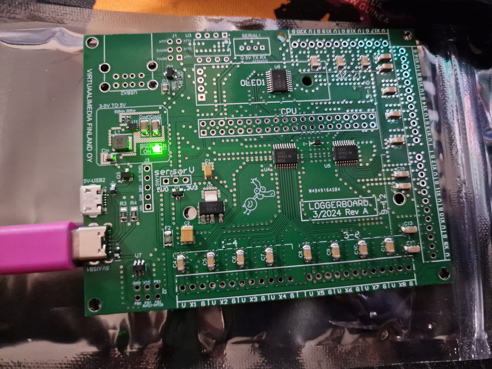
My first PCB design with SMD components pre-assembled in pcbway went south immediately. (Magic smoke...)

The pcb is basically a breakout board for a Pi Zero to connect 20 DHT22 sensors, but with 3-5V to 5V boost converter for external power and selectable 3.3V or 5V sensor voltage.
- It also has level shifters for data lines coming from sensors to gpio.
- Attiny10 smd microcontroller to have full system and sensor reboot possibility.
- Place for dual usb-a connector with power on-off possibility.

I ordered 5 boards from pcbway with smd components and usb-c and micro-usb connectors assembled. I want to solder through hole stuff my self but I did not solder those yet.
I just got the boards. Before powering on the first one I measured that nothing was not shorted and it looked good. Then I connected the usb-c connector to my phones usb charger.
1. First the power on led lit nicely and I was able to measure that the input was 5.125V and after the boost converter it was 4.999V. No problems. (The only thing consuming power at the pcb at this point was the small smd led.)
2. I then proceeded to carefully try to feel out if any component was overheating by just gently touching the top of the components. At this point the smoke came out of the feedback resistor of the boost circuit (Rfbt). (CRCW0402732KFKED CRCW Series 0402 0.063 W 732 kOhm ±1 % ±100 ppm/K SMT Thick Film Chip Resistor).
3. I disconnected the usb power immediately and started searching for shorts but found none.
4. I measured the second pcb for shorts and continuity on power traces.
5. I connected power to the second board thinking the probem with the first could have been a manufacturing flaw. -> Smoke from the input protection diode (D1) between the usb connector and the boost circuit.
6. I have been trying to find the flaw for two days now but cant find one. I already got smoke from third pcb and this time it was the p-mosfet (Q3) after the protection diode before the boost circuit.  |O
All help is appreciated.

Pictures:
https://1drv.ms/f/s!AnfIOtcTpP6Bg4Njyl16cHLvhViyuw?e=eCatYS

Link to circuitmaker project:
https://365.altium.com/files/C33BBF2E-E81A-4FCC-8011-A663D419CE9A

Project files:
https://d3mo.fi/storage/20-sensor-pi-pcb/

What tools is have for debugging:
Fluke multimeters, lab power supply, frequency generator, soldering equipment, internet. :bullshit:

4
Quote
8 bit is 255 steps, duh, but it´s should be more than enough.
T'is what the entertainment world has been using for a good few years .
5
Do I use the right setup?

No. If you want to use decent development tools run the things on a decent development machine and then send the compiled executables to the target. The fad of having to develop on the target is, IMO, a fad that's a bit silly.

Well, you did ask  >:D

Yep, but if the OP is really uncomfortable with setting up a cross-compiler (or in case there isn't one, which is not the case here, but just saying), the closest reasonable approach is to edit your code in whatever programming editor/environment you like and only compile it on the target.

You mean, like this:  https://www.eevblog.com/forum/programming/show-definitions-autocomplete-function-parameters-for-c-(text-editor-over-ssh)/msg5455418/#msg5455418  ?  :P

Yes, pretty much, but not exactly: in the post you mention, this is still cross-compiling, while I suggest an alternative option to just edit the code comfortably on a computer and compile it directly on the target, rather than cross-compile it.
6
I´ve heard the ESPs had some problems with their analog peripherals...

Then again, I have never really used them, so bewarned, search a bit about if that´s the case. I will not deter you, but also won´t encourage you
without doing some search first. Maybe PWM is just fine and will give you even more step ( if they have 16bit timers ).

8 bit is 255 steps, duh, but it´s should be more than enough. Then again, neither LEDs nor human eyes are linear,
so you´ll need the extra steps to produce something pleasing, with relatively not too many steps ( 20 - 25 steps should be anyhow enough ).

Your driver is probably a current driver, but LED brightness is not linear with current. You´d have to linearize the LED power, probably with an
instrument ( there are 40 - 60€ ones, look like multimeters and will probably give you a good enough reading based on your installation also ).
Then you got to logarithmize your data from your readings to match the human eye. Humans are logarithmic creatures.

Example Op Amp for your case seems to be TS321CX5. Single Channel, good at near negative rail.

These should be more than enough for now to be give you a head start.
7
Test Equipment / Re: SDS800X HD Feature/Improvement disscusions
« Last post by eTobey on Today at 10:26:42 pm »
I cant wait...   :popcorn:
8
Beginners / good/cheap headphone aplifier/dac?
« Last post by flaotte on Today at 10:24:34 pm »
I would like to bump sound quality for my computer headphones.
Is there any good circuit for amplifier or even DAC that does not cost a fortune?
Or maybe... is it possible to get a ready to solder KIT?
or should I forget it and get external sound card?

p.s. I use bose QC25 now. They falling apart and will need to be replaced at some point, but it is the most comfortable headphones I ever had. I always work with them on, even without any music playing. Helps me to concentrate.  :bullshit: Any recommendation for replacement?
9
Metrology / Re: HP 3458A on a "Pure Sinewave" UPS
« Last post by EC8010 on Today at 10:17:12 pm »
Mains interference is (fairly) random. Why not explicitly test your transformer/filter with sine waves from a function generator?

For common mode: Short the primary winding, short the secondary winding. Terminate RG58 cable from generator in a through termination. Connect centre BNC pin to shorted primary, outer to chassis. RG58 to oscilloscope, oscilloscope set to terminate input. Centre pin to shorted secondary, outer to chassis.

For differential mode: Terminated signal across unshorted primary. Input of oscilloscope across secondary. Decide whether termination makes more sense.

In both cases, measure spot frequencies between 100kHz and 10MHz. We're talking low RF, here.

But what might a UPS produce that could upset an elderly precision DMM? I wouldn't be in the least surprised to learn that a 3458A has a linear supply using an EI mains transformer. If that's the case, what will upset that transformer is DC. A trapezoid is effectively switched DC and will cause saturation of the transformer's core, leading to excess leakage flux, and that might creep into measurements. The isolating transformer is a high-pass filter, so it might assist. And it might not. A simple oscilloscope trace should tell you what's going on. You don't want to see flat tops on the mains. And yes, I have noted that the thread title includes "Pure sine wave". How pure is pure? I'll bet that a UPS manufacturer's idea of pure is different to mine.

10
Networking & Wireless / Re: HDMI INPUT ON TABLETS
« Last post by ataradov on Today at 10:10:47 pm »
If you are talking about actual tablets that can run an OS, there are probably none. But there are portable monitors like this https://www.amazon.com/10-5inch-Portable-1920x1280P-External-Ultra-Thin/dp/B0C7KPPXTZ/ref=sr_1_1 . This would need an external power supply though.
Pages: [1] 2 3 4 5 6 ... 10 Next