Author Topic: T962 Reflow Oven?  (Read 16480 times)

0 Members and 1 Guest are viewing this topic.

Offline ttt

  • Regular Contributor
  • *
  • Posts: 87
  • Country: us
Re: T962 Reflow Oven?
« Reply #50 on: July 11, 2020, 08:56:55 pm »
So I just finished upgrading my T962A+ with a couple of circulation fans. This was not obvious as the fan motor needs to be outside the chamber of course.

Ingredients:
- A couple of cheap RC DC hobby motors
- Shaft holder is a 50mm M6 all thread with 3.5mm bore.
- Drive shaft is a 2mm Stainless Steel Rod with threads at the end
- flat steel sheet as fan blades (Don't use aluminum, it'll droop).
- Extra hardware to hold it all together

Conclusion after reflowing a few boards: Night and day. Lead free solder melts evenly and consistently on my 300x150mm boards.  And that's with the default controller board.

This was inspired by Jerry Walkers mod: https://youtu.be/9026Odx_jOw?t=752
 
The following users thanked this post: jpanhalt

Online jpanhaltTopic starter

  • Super Contributor
  • ***
  • Posts: 3476
  • Country: us
Re: T962 Reflow Oven?
« Reply #51 on: July 11, 2020, 09:06:13 pm »
Nice job.  I still have very limited experience.  Once Springs comes, I am busy on a small farm.  Improving circulation, not exhaust, seems an obvious way to improve.
 

Offline peter-h

  • Super Contributor
  • ***
  • Posts: 3697
  • Country: gb
  • Doing electronics since the 1960s...
Re: T962 Reflow Oven?
« Reply #52 on: June 22, 2021, 11:17:33 am »
This is just an update in case anybody is looking to buy this oven.

I bought one one Ebay. At £150 one can't argue even if it is crap :) and indeed it is pretty well crap!

Good points:

Mechanically sturdy, the drawer works. Chinese do sturdy metalwork :)
Very cheap!

Bad points:

Airflow is crap. The design is truly dumb. To achieve circulation, they use an external fan to blow outside air into the oven! No domestic oven does that; they all have an internal impeller and they recirculate the internal air. If you set the fan speed anything above the absolute min at which is just about runs, the oven never reaches any soldering temperature, and there are huge differences between the two thermocouples - up to 80C.

Generally shoddy build. Masking tape all over the place inside - smells when hot and has to be replaced with kaptop tape - this issue is documented all over the internet but the mfg obviously doesn't read it :)

I installed the ES Technical controller replacement which was another £150
https://www.estechnical.co.uk/products/reflow-oven-controllers

This is a good product. However I have to say the installation is not trivial. One has to cut in half the existing controller PCB, so just the mains switching portion is left. The procedure involves unsoldering a terminal block, which would be difficult but luckily I have a bandsaw and when I cut the board across I just sawed right through the terminal block and the unwanted part just fell off :) They should have just done everything on one PCB. But it works great. Of the two thermocouples they use just the 1st one, and it seems to be the 2nd one which shows the duff (way too high) temperature.


Using a precision PT100 thermometer and by pulling out the two TCs I proved that both read accurately, within 1-2C, with the right temps displayed on the LCD. So it is just an airflow issue.

Luckily my oven was an older model which does not have the extraction duct on the fan, so I didn't need to do a more difficult mod which involves removing some "automatic" slats.

I think the oven needs a mod with an internal impeller, driven from a little DC motor. I might install that later, probably via the bottom which is accessible (the oven will need taller feet fitted). But it may not be needed if I find that actual measurements on a PCB are ok.

The ES board has a serial output on which it streams various parameters in CSV format, continuously. Not tried this yet.

I will report in due course on how this oven works for soldering.
Z80 Z180 Z280 Z8 S8 8031 8051 H8/300 H8/500 80x86 90S1200 32F417
 

Online jpanhaltTopic starter

  • Super Contributor
  • ***
  • Posts: 3476
  • Country: us
Re: T962 Reflow Oven?
« Reply #53 on: June 22, 2021, 12:05:33 pm »
Bad points:

Airflow is crap. The design is truly dumb. To achieve circulation, they use an external fan to blow outside air into the oven! No domestic oven does that; they all have an internal impeller and they recirculate the internal air. If you set the fan speed anything above the absolute min at which is just about runs, the oven never reaches any soldering temperature, and there are huge differences between the two thermocouples - up to 80C.


I can only agree in part.  Yes, the air flow might be improved; however, I found with my independent TC's  (as described earlier) that temperature control across the oven is better with higher fan speeds.  Each TC can be adjusted to read relatively close to the external TC's.  Attached is the Kester recommended profile for 63/37 solder.   Second attachment is actual profile shown on the T962 screen.  Actual peak was 235°C.  Leaded solder does reflow.

Sorry for the blurred image.  Handheld and close ups do not work well for me.

EDIT: Original control board with United Engineering firmware.
« Last Edit: June 22, 2021, 12:09:28 pm by jpanhalt »
 

Offline peter-h

  • Super Contributor
  • ***
  • Posts: 3697
  • Country: gb
  • Doing electronics since the 1960s...
Re: T962 Reflow Oven?
« Reply #54 on: June 22, 2021, 01:09:54 pm »
I found that with higher fan speeds the oven never reaches the required 220C or so (fairly obviously due to the amount of cold air arriving) and the controller gives up with an error message.
Z80 Z180 Z280 Z8 S8 8031 8051 H8/300 H8/500 80x86 90S1200 32F417
 

Online jpanhaltTopic starter

  • Super Contributor
  • ***
  • Posts: 3476
  • Country: us
Re: T962 Reflow Oven?
« Reply #55 on: June 22, 2021, 02:00:51 pm »
With different firmware and hardware, my conditions may not apply to you.

Here are some data from my testing and comparing temperatures in °C on the T962 screen with TC readings (Fluke):
[plain]
Screen "actual" : 202°
Fluke TC :          199°
Oven TC (L):      200°
Oven TC (R):      202°
Fan speed:         30
Cold Junction:    21.5°

TC settings:
L(gain):      1.0
L(offset):    -5.00
R(gain):      0.82
R(offset):   +0.25
[/plain]

I have vacillated between a minimal fan speed of 30 and 20.  My current setting is 20.  Hope this helps.  BTW, it's "Unified Engineering," not United.

Edit: changed fan speed to minimal fan speed

« Last Edit: June 22, 2021, 02:12:01 pm by jpanhalt »
 

Offline peter-h

  • Super Contributor
  • ***
  • Posts: 3697
  • Country: gb
  • Doing electronics since the 1960s...
Re: T962 Reflow Oven?
« Reply #56 on: June 22, 2021, 02:39:46 pm »
Maybe your "fan30" is my "fan10". These controllers are still applying full mains voltage to the fan, but on a low duty cycle. This is the only way; the fans are not capable of being speed controlled like some DC motor, or a 3 phase brushless AC motor.

I also see that you have done what looks like thermocouple calibration. You have 1.0 on one and 0.82 on the other. That is a dramatic correction. It corresponds to about 40C at 200C. Thermocouples should not need that. They should be accurate to within a few degrees C and usually better. I do this in my day job.

The controller I am using doesn't have any calibration options and it should not need them.
Z80 Z180 Z280 Z8 S8 8031 8051 H8/300 H8/500 80x86 90S1200 32F417
 

Offline peter-h

  • Super Contributor
  • ***
  • Posts: 3697
  • Country: gb
  • Doing electronics since the 1960s...
Re: T962 Reflow Oven?
« Reply #57 on: June 23, 2021, 01:28:46 pm »
Just a quick Q:

I am finding that the actual PCB temp is way more than what the controller is achieving according to its thermocouple sensor.

On the peak (reflow) section I have 220C for 10 secs.

To check the temp, with a PT100 thermometer but which has a greater mass than just a tiny TC, I extended this section to 100 secs, to give it time to stabilise.

I measured over 270C! And of course there was a lot of damage to the PCB... Yet I know the oven sensor is accurate, to 1-2C. It is about 15cm above the PCB. If it was much lower, it would hit the back of the drawer lip when the drawer is pulled out.

I am wondering if the profile settings in these ovens are basically "wishful thinking" and have to be "iteratively hacked" so the 10 secs is very short so as to just reach 230C for a few secs, so it just happens to work right? One would have to use a sample board and a thermocouple on it.

But even the preheat platform portion of the profile (which is 130C) is measured at about 160C.
« Last Edit: June 23, 2021, 04:11:46 pm by peter-h »
Z80 Z180 Z280 Z8 S8 8031 8051 H8/300 H8/500 80x86 90S1200 32F417
 

Offline peter-h

  • Super Contributor
  • ***
  • Posts: 3697
  • Country: gb
  • Doing electronics since the 1960s...
Re: T962 Reflow Oven?
« Reply #58 on: June 24, 2021, 07:25:49 am »
Another test today, this time with a thermocouple (TC) thermometer, with a TC similar to the built-in ones.

On a piece of PCB-like material, the temp seen was 70C higher.

That is obviously completely useless. Clearly the built-in sensors are not picking up the effect of the IR heating.

I am wondering whether a solution must involve attaching a piece of dark material, say black anodised aluminium, to the sensor(s) used by the controller?
Z80 Z180 Z280 Z8 S8 8031 8051 H8/300 H8/500 80x86 90S1200 32F417
 

Offline peter-h

  • Super Contributor
  • ***
  • Posts: 3697
  • Country: gb
  • Doing electronics since the 1960s...
Re: T962 Reflow Oven?
« Reply #59 on: June 25, 2021, 08:14:58 am »
I have concluded this oven is completely useless as it is, so I am installing a fan inside.

There are two versions of this oven for sale. One, which is the Puhui one, has an exhaust duct on the back. Obviously the fan in that one runs in the opposite direction, so the fumes can be extracted. But that one also suffers from an even worse temperature control, because there is close to zero airflow inside. That one has auto-opening slats, and the ES Tech replacement controller kit comes with a piece of louvred metal to replace these slats, plus they ask to turn the fan around so it runs like in the old model (but then fume extraction doesn't work). The other is the one which is all over Ebay and is a counterfeit "T962", and that has no exhaust duct, and the fan draws air into the oven.

This is the Puhui one with the duct: https://www.te168.com/infrared-reflow-oven-t-962-products/


This is the counterfeit one, which is practically every T962 on Ebay UK e.g. e.g. https://www.ebay.co.uk/itm/123687959494


I don't think they differ internally as regards the sensor positioning, so the temperature distribution is likely to be equally useless in both.

Experiments show that the colour of the PCB dramatically changes the temperature at its surface. Radiation alone is thus no good.

One solution might be to mount the thermocouple used by the controller (whichever controller - the original or a retrofit) onto a piece of PCB material which lays next to the PCB. That would involve a length of TC cable flopping around inside the oven and potentially displacing any components which at that point are just sitting on solder paste. I have in fact done that with #2 thermocouple (the ES controller uses only the #1) and have it hanging out of the side of the oven, so it can be fed back through the gap around the front of the drawer, to measure whatever temperature you want to measure.

So I am installing a little impeller inside. A motor outside and a 2cm diameter model boat propeller inside. Will post pics when done.

I can't understand how people can sell this POS... The one way I can see it - as shipped - working and delivering anywhere near the right temp at the PCB surface is by tweaking the profile temps to be much lower than the actual numbers desired. In fact it I think it "works" for most people because running the preheat platform at say 170C instead of 130C doesn't actually damage anything (and it doesn't reach the 170C until near its end anyway) and then running the 230C bit at say 270C also doesn't damage anything because in the 10 secs or so duration of that section the PCB doesn't reach much more than 230C anyway! So it works by luck.

One does need an exhaust duct otherwise every time you use the oven, it will stink out the whole room (or whole house, if at home) and it continues to smell badly for many hours afterwards. I have replaced the masking take with kapton tape, btw...
« Last Edit: June 29, 2021, 10:14:00 am by peter-h »
Z80 Z180 Z280 Z8 S8 8031 8051 H8/300 H8/500 80x86 90S1200 32F417
 

Offline peter-h

  • Super Contributor
  • ***
  • Posts: 3697
  • Country: gb
  • Doing electronics since the 1960s...
Re: T962 Reflow Oven?
« Reply #60 on: July 07, 2021, 02:04:41 pm »
Update:

I tried various ways of installing an internal fan. The tricky thing is that whatever you do has to work at 230C or more... This is the final version. The big brass cylinder has two ball bearings in its ends


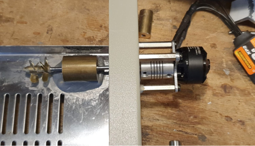
It would have worked much better with a bigger propeller, so one needs to mount the shaft as high up in the drawer front as possible. This mod is very noisy but who cares...

But it didn't fully fix the issues, which are basically

- the mainly IR (no convection) heating produces an extremely uneven temp distribution, with 220C controller setpoint (and feedback) producing easily 290C on the PCB (the standard hack seems to be to reduce the 220C setpoint in the profile!) and even the 130C setpoint producing 170C.

- if you turn up the fan a bit more, you just get cold air drawn in, which cools the sensing thermistor much more than it cools the board

- the IR tubes are much too close to the PCB, so a spot under one gets perhaps 30C hotter than elsewhere.

So the only way to make this cheap oven work at all usefully if you care about the temperature to which you cook your components is to bring out the sensing thermocouple (the ES replacement controller uses just one sensor; no idea about the factory fitted one) on a lead and attach it to the PCB being soldered! And as you would expect, that works pretty well. Dramatically improves things - at the point where the sensor is touching the PCB. The second thermocouple is being used to measure whatever else; I used it to keep an eye on the bottom temperature which goes no higher than 150C.

But one still has variations around the PCB. With the combination of sensing the PCB temperature in the middle of the PCB, and the above model boat air stirrer, it is almost usable.

Another variable is the fan speed. This oven requires fume extraction otherwise you stink out the whole place! So the fan has to extract air, not blow it in. I reversed mine, since the oven I got (UK Ebay) didn't have the extraction duct. I set it to just 5%, and 10% is pretty similar, with the above model boat propeller mod running to keep the air mixed. 10% gives better fume extraction, obviously. I settled on 8%. This oven has a huge hole in the bottom through which the fan draws in cold air; this is incidentally necessary to avoid the bottom of the board getting too hot. I am seeing 150C max, as stated above, which is OK. If you run the fan too fast, the heating system will be unable to reach the setpoint (say 220C).

I spent way more time messing with this thing than was worth it, but at least I now have a compact oven - much smaller than the ones which actually work out of the box (and cost a lot more, like 1-2k).

Since I have a second sensor I have been running tests between board centre and board edges. Due to temp variations due to poor air mixing and highly localised heating from the IR tubes which are very close to the PCB, you can't do big boards in this oven. Much smaller than the drawer size, and I reckon 12x12cm is the max which will work. However, it may be that a board big enough to cover the whole drawer bottom will also work, because it will reduce the cooling airflow around the PCB edges.

Probably the best modification for this oven is a large, say 10cm dia, slow running fan, hung from above. I have seen a photo where somebody did that. It's not easy, due to a lack of space for the motor, which would need to be a "pancake" type motor. Also you would need to strip out the whole upper insulation layer to get access, which would be messy as hell.

There are so many things wrong with this oven that anything it going to be hard work, unless you are happy with variations of some 30C across the PCB. I think I have got it down to the 10-20C range, which is not too bad.

I am now working on a means of placing the sensor on the upper PCB surface, using some sort of spring loaded probe attached to the edge of the drawer. The obvious way is to bring the wire in from underneath, through the slots in the drawer bottom, but that needs the PCB to have a hole somewhere in it through which the sensor can come up, and then you bend it over so the TC junction sits on the upper surface. But that way it is easy to short circuit the thermocouple wires, and even touching one of them on the drawer metal produces a way-off reading (as one would expect).

Another thing I will try is using a sheet of aluminium mesh above the PCB, suspended just under the IR tubes, to even out the heating.

Reading some of the many threads online about T962 oven mods, it makes me smile to read all the accounts of where people burnt up various components. They obviously had no idea at all what temperature their PCB was actually reaching...

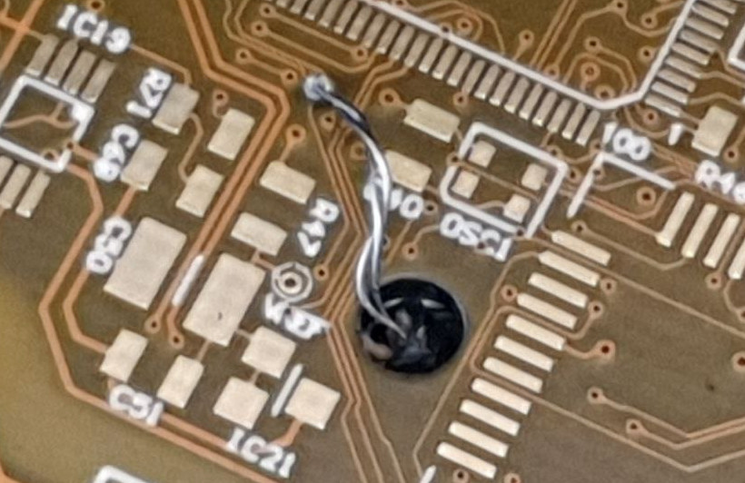
This shows the TC sensor coming up from underneath, and touching the PCB upper surface. It is important to expose at least 1cm of the fine wire to the air above the PCB, but not have any of it electrically touching the drawer bottom


I've just done a run and everything is within 10C. The peak temps at 220C setpoint were 224 and 211 in the centre and edge of this 10x10cm board.
« Last Edit: July 07, 2021, 04:28:54 pm by peter-h »
Z80 Z180 Z280 Z8 S8 8031 8051 H8/300 H8/500 80x86 90S1200 32F417
 

Offline peter-h

  • Super Contributor
  • ***
  • Posts: 3697
  • Country: gb
  • Doing electronics since the 1960s...
Re: T962 Reflow Oven?
« Reply #61 on: July 09, 2021, 08:22:13 am »
One correction: ref the above pic, one should untwist the thermocouple wires, so the tip is the only junction.

Z80 Z180 Z280 Z8 S8 8031 8051 H8/300 H8/500 80x86 90S1200 32F417
 

Offline Miti

  • Super Contributor
  • ***
  • Posts: 1324
  • Country: ca
Re: T962 Reflow Oven?
« Reply #62 on: July 21, 2021, 06:24:13 pm »
I agree that T962 is a crappy oven. I bought a used one for $120 CAD and I did all the modifications that circulates on the internet. Well, at least the Kapton tape, the cold junction, the FW and the grounding. Moreover, I installed some sturdy standoffs to raise it up from the desk, before it catches fire.
I have a temperature gradient of 10 to 20 C between the left and the right side. Also, there’s quite a difference between the temperatures indicated by its TCs and two low mass TCs attached to the board. I wanted to replace the two fixed TCs with two flexible ones that I can attach to the boards when I reflow, but  after spending so much time trying to make something out of it, I lost my interest. I went back to the toaster oven and assembled few perfect boards. No controller, no burned boards or components, all manual and visually watching the temperature.
Fear does not stop death, it stops life.
 

Offline phil from seattle

  • Super Contributor
  • ***
  • Posts: 1029
  • Country: us
Re: T962 Reflow Oven?
« Reply #63 on: July 22, 2021, 03:02:36 am »
I agree that T962 is a crappy oven. I bought a used one for $120 CAD and I did all the modifications that circulates on the internet. Well, at least the Kapton tape, the cold junction, the FW and the grounding. Moreover, I installed some sturdy standoffs to raise it up from the desk, before it catches fire.
I have a temperature gradient of 10 to 20 C between the left and the right side. Also, there’s quite a difference between the temperatures indicated by its TCs and two low mass TCs attached to the board. I wanted to replace the two fixed TCs with two flexible ones that I can attach to the boards when I reflow, but  after spending so much time trying to make something out of it, I lost my interest. I went back to the toaster oven and assembled few perfect boards. No controller, no burned boards or components, all manual and visually watching the temperature.
This!  Every time I think about getting a "real" reflow oven, I remind myself that just eyeballing the board temp in my $10 Black and Decker convection oven has never failed me.  Last week I did a 160 component 100x100mm board and it came out perfect. There is a cold-ish spot in the middle that I have to work around but I've never had to cook it at the top reflow temp for longer than the datasheet profiles
 

Online jpanhaltTopic starter

  • Super Contributor
  • ***
  • Posts: 3476
  • Country: us
Re: T962 Reflow Oven?
« Reply #64 on: July 22, 2021, 09:58:13 am »
When I was looking for a reflow oven (which is why I started this thread), I also was considering a toaster oven option.  I ordered the controller from Rocket Scream in Malaysia (https://www.rocketscream.com/blog/product/tiny-reflow-controller-v2/ ).  A short time later I came across an anxious seller for the T-962 (new, in box, $100) and bought it.

I haven't seen that controller mentioned here yet and think others might find it interesting.  The seller was quite prompt in shipping, but DHL was slow as can be.  I think it went to Germany (Frankfurt) before coming to the US.  The build is very nice, and it worked in a test rig.  It may be worth mentioning that the seller was using it with a toaster oven to manufacture his products until apparently recently, when he got a Phuhui T-937M.  He had problems with that similar to T-962 problems (See: comments on his site).
 

Offline peter-h

  • Super Contributor
  • ***
  • Posts: 3697
  • Country: gb
  • Doing electronics since the 1960s...
Re: T962 Reflow Oven?
« Reply #65 on: July 25, 2021, 12:03:39 pm »
I doubt the controller is the main issue with these ovens. It is the temperature measurement which is rubbish. You cannot use IR (i.e. radiation) emitters, sense the temperature some 2cm above the PCB with a thin thermocouple, and expect the PCB to be anywhere near right - except by luck.

I posted the mods I did above. I did two other mods:

I replaced the brushless model plane motor with a Chinese fake of a smooth running Maxon motor, to reduce the vibration
https://www.ebay.co.uk/itm/252386889509


I replaced the thermocouples (which were the same type of TC wire as originally used - grass fibre insulated) with a much thinner PTFE insulated TC wire
https://www.ebay.co.uk/itm/383806095552

which as you can see is small enough to poke up through a PCB hole from underneath


The result is dramatic, especially from using the thin wire. The measured PCB surface temp now follows the setpoint well. On the standard profile, at the 130C platform the board reaches 140C (basically the ES controller overshoots a bit) and on the brief 220C platform it reaches 225C.

The propeller modification now makes very little difference, which is quite funny since I spent so much time on it :)
Z80 Z180 Z280 Z8 S8 8031 8051 H8/300 H8/500 80x86 90S1200 32F417
 

Offline peter-h

  • Super Contributor
  • ***
  • Posts: 3697
  • Country: gb
  • Doing electronics since the 1960s...
Re: T962 Reflow Oven?
« Reply #66 on: July 30, 2021, 09:12:03 am »
I am getting good results by placing the measuring sensor on a piece of PCB, next to the PCB being soldered. That way one is not risking nudging some components when trying to place the sensor.
Z80 Z180 Z280 Z8 S8 8031 8051 H8/300 H8/500 80x86 90S1200 32F417
 

Offline Southerner

  • Regular Contributor
  • *
  • Posts: 116
  • Country: us
Reflow Oven. Where is the LPC2134 Firmware Hex file?
« Reply #67 on: November 04, 2021, 05:41:37 am »
I was trying to find what I need to do the flash for the LPC2134 cpu in the T962 reflow oven that I have but have never tried to use.  I can find the github repo for it (but it is a few years old) at:
https://github.com/UnifiedEngineering/T-962-improvements

Also this page:
https://github.com/UnifiedEngineering/T-962-improvements/wiki/Flashing-the-LPC21xx-controller
supposedly tells me how to flash it.  It tells me to go to:
https://github.com/UnifiedEngineering/T-962-improvements/releases

to get the hex file but there is no hex file there that I could find.  It does not really tell me how to make the hex file either.  The wiki is here:
https://github.com/UnifiedEngineering/T-962-improvements/wiki

A hackaday page here:
https://hackaday.com/2014/11/27/improving-the-t-962-reflow-oven/
has some info but does not tell me how to create that hex file that does not appear to exist in the code (the zip file) or at the release page.  I suspect that I run make or makefile but am surprised that the hex file is not already there.  Or am I just missing it?

I am a Windows user and running Windows 7 so I was not sure how to create that Hex file that sounds like it should already be there but I did not see it.

Thank you for your help.
 

Offline Kean

  • Supporter
  • ****
  • Posts: 2091
  • Country: au
  • Embedded systems & IT consultant
    • Kean Electronics
Re: Reflow Oven. Where is the LPC2134 Firmware Hex file?
« Reply #68 on: November 04, 2021, 06:00:37 am »
https://github.com/UnifiedEngineering/T-962-improvements/releases

to get the hex file but there is no hex file there that I could find.

Click on Assets to expand the list and you'll see a link to download the hex file
https://github.com/UnifiedEngineering/T-962-improvements/releases/download/v0.5.2/T-962-controller.hex
 
The following users thanked this post: Southerner

Online jpanhaltTopic starter

  • Super Contributor
  • ***
  • Posts: 3476
  • Country: us
Re: T962 Reflow Oven?
« Reply #69 on: November 04, 2021, 09:29:19 am »
I used Flash Magic and an ordinary Windows PC to do the flashing with an FTDI serial cable: TTL-232R-3V3. 
 

Offline Southerner

  • Regular Contributor
  • *
  • Posts: 116
  • Country: us
Re: Reflow Oven. Where is the LPC2134 Firmware Hex file?
« Reply #70 on: November 05, 2021, 07:25:27 am »
Click on Assets to expand the list and you'll see a link to download the hex file
https://github.com/UnifiedEngineering/T-962-improvements/releases/download/v0.5.2/T-962-controller.hex
I posted the question to the github page but the reply came back to look in https://github.com/UnifiedEngineering/T-962-improvements/releases which was the link I had mentioned not being able to find the file.  Later a friend told me I had to expand the Assets box to see the file.  That was not clear before.  Thank you all for the help.
 

Offline Southerner

  • Regular Contributor
  • *
  • Posts: 116
  • Country: us
Re: T962 Reflow Oven?
« Reply #71 on: November 05, 2021, 07:58:18 am »
- if you turn up the fan a bit more, you just get cold air drawn in, which cools the sensing thermistor much more than it cools the board

Another variable is the fan speed. This oven requires fume extraction otherwise you stink out the whole place! So the fan has to extract air, not blow it in. I reversed mine, since the oven I got (UK Ebay) didn't have the extraction duct. I set it to just 5%, and 10% is pretty similar, with the above model boat propeller mod running to keep the air mixed. 10% gives better fume extraction, obviously. I settled on 8%. This oven has a huge hole in the bottom through which the fan draws in cold air; this is incidentally necessary to avoid the bottom of the board getting too hot. I am seeing 150C max, as stated above, which is OK. If you run the fan too fast, the heating system will be unable to reach the setpoint (say 220C).


Since I have a second sensor I have been running tests between board centre and board edges. Due to temp variations due to poor air mixing and highly localised heating from the IR tubes which are very close to the PCB, you can't do big boards in this oven. Much smaller than the drawer size, and I reckon 12x12cm is the max which will work. However, it may be that a board big enough to cover the whole drawer bottom will also work, because it will reduce the cooling airflow around the PCB edges.

You mention that a slower fan would be desirable. What about this slow speed motor
similar to the one you used but only 13rpm:
https://www.ebay.com/itm/122698927305

Also what model boat motor prop did you use?

If not,  then what about cutting a vent in the side and using a tiny cage fan to push in air? 
Or would that be too much circulation?  My concern with a mod like yours is keeping the
propeller and shaft out of the way and that is why I ask about using a tiny cage fan
(if one can be found) so that it is not in the heat bay and not close to it.

Thank you.
 

Offline Southerner

  • Regular Contributor
  • *
  • Posts: 116
  • Country: us
Re: Which mods for T962 Reflow Oven?
« Reply #72 on: November 05, 2021, 08:01:46 am »
I have looked through the github page and a couple hackaday pages about T962 mods but I do not see even on the github wiki page any suggestions for which mods to do and which ones would be nice or which ones are not worth the effort.  Granted replacing the duct tape with kapton tape and flashing the firmware and probably the cold temp probe I would assume would be the mods that should be done.  Are there others that should be done? Which ones are not worth the effort or accomplish very little?

Thank you.
 

Online jpanhaltTopic starter

  • Super Contributor
  • ***
  • Posts: 3476
  • Country: us
Re: T962 Reflow Oven?
« Reply #73 on: November 05, 2021, 08:14:56 am »
The tape, flash, and cold junction are the three mods I did.  It seems the vast majority of users has stuck to those too and seem happy with them.   If you want to turn your Yugo into a Lexus, you are free to try, but they both still work for getting groceries.       
 

Offline EE-digger

  • Frequent Contributor
  • **
  • Posts: 348
  • Country: us
Re: T962 Reflow Oven?
« Reply #74 on: November 06, 2021, 02:00:57 pm »
I've only had the T-962 for three days and also did the tape, flash and cold junction.

Since I had to get a small job done, I had to create a pretty drastic profile to melt just tin-lead solder.

After spending hours with this unit, I measured and noticed a number of things.  One which is a killer for uniformity is that the quartz elements are much brighter at the left end than at the right.  Too lazy to measure but I would estimate that the right side looks as if it were getting 50- 60% of the power.

This has to be due to crappy tube construction with non-uniform wire diameter, perhaps stretched during forming (although that IS a stretch indeed).

I'd like to hear other comments on the tubes.  Are yours this uneven?

And as another poster mentioned, the tubes are much too close to the board.  I also picked up a Black and Decker toaster oven for $35 a week ago and that thing runs rings around the T-962, with my hand as the PID controller.  The distance to the board is nice (and adjustable) and the tubes are highly uniform from end to end.

While the T-962 is definitely cute and space saving, I don't believe that it is useful for much with the tubes I have. 

And, raising the board any distance other than to break contact with the floor is just an invitation for french fried substrates.

« Last Edit: November 06, 2021, 02:03:47 pm by EE-digger »


Share me

Digg  Facebook  SlashDot  Delicious  Technorati  Twitter  Google  Yahoo
Smf