Author Topic: Buffer for Kelvin Varley Divider  (Read 8953 times)

0 Members and 1 Guest are viewing this topic.

Offline CrossphasedTopic starter

  • Regular Contributor
  • *
  • Posts: 127
  • Country: us
Buffer for Kelvin Varley Divider
« on: May 08, 2019, 05:09:56 am »
Hello friends,

I have a Julie Research Labs Kelvin Varley Divider, and I'm trying to make it usable as a precision voltage source.


When I first received the unit it wasnt working optimally, on certain dial settings the readings would be "jumpy" and not stable. No amount of turning the knobs cleaned the switches enough to work properly. This past weekend I gave the switches a thorough cleaning with contact cleaner and De-oxit, now the divider is working much better. There still is a small amount of loading error though, that I'm hoping to address with a properly designed buffer.

Here's what I've observed with the loading error-
Starting with an aged and stable AD587 (which outputs slightly over 10V) as the voltage source to the divider, and a DMM with 10G input impedance to read the output. Then adjusted the knobs until the DMM reads exactly 10.00000V.
Next adjusted the primary dial from 9->0, 1 volt at a time. Here's the readings:
8.99995
7.99992
6.99990
5.99988
4.99986
3.99984
2.99982
1.99981
0.99980

So I lose ~200uV over the range of the first dial. I'd like to improve this. Also I'd like a higher output current than the divider can provide. Examining the selection of low bias current opamps, I found the ADA4530. Its not cheap at 25 bucks, but it seems to fit my needs: 20 femtoamps @ 25C bias current, different offset voltages for different common mode voltage. I was hoping to get some pointers on how I might design a buffer to to correct the offset voltage for different input voltages.

To start I was thinking something kind of like this, please let me know if I've made any mistakes:

 would this configuration be appropriate to correct for offset voltages? Or perhaps using a DAC instead of 5V as the source to the pot? Or would it make sense to implement some sort of autozero function? Reading the datasheet the input must be carefully guarded to get the low bias current, I'm not sure if having switches connected to the non inverting input would be a bad idea for leakage currents?

I was trying to think of ways to reduce any bias current drawn from the divider, and thought there must be some way to provide part of the bias current from the output. Would something like this work?


Looking through various app notes, I saw this interesting circuit, which is supposed to have near infinite input impedance as the output voltage approaches the input voltage:

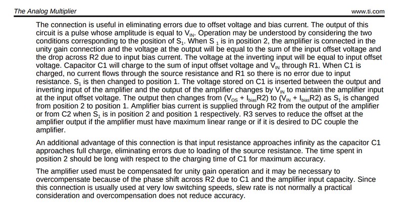


Any thoughts you guys have? Thanks so much!!  :-+

Edit: I should also mention I've attempted making a buffer already. I tried both the LTC2057, & the AD8638. They both gave nearly identical results.  So starting with an output from the divider that reads 10.00000 on the meter, then inputting that to buffer, then reading buffer output with meter, here's the numbers I got:
9.99985
8.99979
7.99977
6.99975
5.99972
4.99970
3.99968
2.99966
1.99964
0.99962
« Last Edit: May 08, 2019, 06:54:41 am by Crossphased »
 

Offline maginnovision

  • Super Contributor
  • ***
  • Posts: 1963
  • Country: us
Re: Buffer for Kelvin Varley Divider
« Reply #1 on: May 08, 2019, 05:55:37 am »
What's the specified linearity for the divider?
 

Offline CrossphasedTopic starter

  • Regular Contributor
  • *
  • Posts: 127
  • Country: us
Re: Buffer for Kelvin Varley Divider
« Reply #2 on: May 08, 2019, 06:48:00 am »
From Tins website, it looks like 1 ppm:
https://xdevs.com/doc/JRL/Julie_Research_Labs_VDR1067_VDR307_Kelvin_Varley_Voltage_Divider_Operator_Manual.pdf

So at 10V, that should be 10uV error
« Last Edit: May 08, 2019, 06:55:24 am by Crossphased »
 

Offline Kleinstein

  • Super Contributor
  • ***
  • Posts: 14172
  • Country: de
Re: Buffer for Kelvin Varley Divider
« Reply #3 on: May 08, 2019, 09:27:10 am »
The ADA4530 is a super low bias amplifier, but with quite some noise and voltage offset.
Assuming a source impedance of some 50-100 K a more suitable buffer would be something like a precision amplifier, so more like an AZ OP like LTC2057 or maybe AD8628 with supply bootstrapping.

The AD8628 has less bias and lower current noise, but is only 5 V so would likely need bootstrapping of the supply. A bootstrapped supply also improved linearity.

It a balance to find between noise and bias current.
« Last Edit: May 08, 2019, 09:30:13 am by Kleinstein »
 
The following users thanked this post: TiN, hwj-d

Offline Echo88

  • Frequent Contributor
  • **
  • Posts: 826
  • Country: de
Re: Buffer for Kelvin Varley Divider
« Reply #4 on: May 08, 2019, 10:55:24 am »
Very interesting topic in itself; sadly i never built one. Good thing it already has been discussed already: https://www.eevblog.com/forum/projects/very-low-bias-current-op-amp-to-buffer-a-kelvin-varley-divider/25/
You could also just use the buffer from AN86 Page 9 or pick a suitable AZ-OP-Amp from my excel-list in the mentioned thread, if youre feeling not ready to use a bootstrapped power-supply yet.
 

Offline The Soulman

  • Frequent Contributor
  • **
  • Posts: 949
  • Country: nl
  • The sky is the limit!
Re: Buffer for Kelvin Varley Divider
« Reply #5 on: May 08, 2019, 11:08:48 am »
What dmm are you using and does it read zero when shorting the input?
The numbers you've posted doesn't look like its loading down the kvd to me, also 10 giga Ohm input impedance already is a lot,
and difficult to improve on without adding to much noise and (more) dc-offset.
 

Offline Conrad Hoffman

  • Super Contributor
  • ***
  • Posts: 1930
  • Country: us
    • The Messy Basement
Re: Buffer for Kelvin Varley Divider
« Reply #6 on: May 08, 2019, 12:08:58 pm »
Those dividers are rarely off by more than 1-2 ppm. You have to be careful with grounding between the source, divider and meter. Jim Williams had a buffer in one of his app notes for LT. A 10 meg meter should be quite sufficient. Watch out for thermal errors. Use untinned copper wire (bell wire). I use wire pulled from old phone cables. Watch out for the bananas used with the meter, as those can be pretty horrible.
 

Offline Dr. Frank

  • Super Contributor
  • ***
  • Posts: 2382
  • Country: de
Re: Buffer for Kelvin Varley Divider
« Reply #7 on: May 08, 2019, 12:49:53 pm »
This KV has 100k impedance, so 10 pA of bias current will create about 0.1ppm error at about every setting.

Please specify, which bench DMM you're using.  This >10 GOhm specification for your DMM is in-appropriate, bias current is the key paramter.
The usual Keysight DMMs have max. 20pA, and < 2ppm INL,  and therefore should not create such big linearity errors.
All readings must be done in the fixed 10V range, and offset at zero setting has to be subtracted upfront.

If all these hints are already implemented, then I really wonder, whether the KV is damaged, or single resistors have drifted too much.. is it possible to trim the first decade in this instrument?

For output buffering, fA opamps are the wrong choice, due to their high offsets, (and due to the unnecessarily low bias currents.)

Instead you need a chopper /zero drift opamp with relatively low bias current in the pA range, the LTC 2057 for example has typ. 30pA  but max. 200pA, which is too high.

Better use others, with higher noise, but < 20pA bias current. LTC2054 could be an alternative, but max bias is not specified properly.
The older ones, like LTC 1052 have typ. 1pA, max. 30pA @ 25°C.

Frank
 
The following users thanked this post: msliva, hwj-d

Offline TiN

  • Super Contributor
  • ***
  • Posts: 4543
  • Country: ua
    • xDevs.com
Re: Buffer for Kelvin Varley Divider
« Reply #8 on: May 08, 2019, 02:55:15 pm »
ADA4522 is also worth to consider.

Quote
is it possible to trim the first decade in this instrument?

First 3 decades of these JRL KVDs are in oil tanks. Might be quite tricky to trim.


Photo credit goes to China metrology enthusiasts.
YouTube | Metrology IRC Chat room | Let's share T&M documentation? Upload! No upload limits for firmwares, photos, files.
 

Offline Kleinstein

  • Super Contributor
  • ***
  • Posts: 14172
  • Country: de
Re: Buffer for Kelvin Varley Divider
« Reply #9 on: May 08, 2019, 03:07:21 pm »
The ADA4522 is even higher bias than the LTC2057. It's more like a cheaper alternative and might need compensation of the bias current. At the pA level one would need to check the bias currents anyway, as there can be additional current from the protection and filter parts and board. The next step to some compensation is not that large.

The LTC1052 is a good low bias option. Another low bias one is AD8551.
 

Offline guenthert

  • Frequent Contributor
  • **
  • Posts: 712
  • Country: de
Re: Buffer for Kelvin Varley Divider
« Reply #10 on: May 08, 2019, 03:56:31 pm »
[..]
There still is a small amount of loading error though, that I'm hoping to address with a properly designed buffer.
[..]
Is there truly an error due to load?  You might want to determine the bias current of your DMM (at those voltages), it might be negligible.

To get the best performance, those deviders are used w/o load ('potentiometer method'), see https://doc.xdevs.com/doc/Fluke/appnotes/nf_ncsl02.pdf for an extreme example.  No buffer needed, i.e. no offset correction needed.
 

Offline tggzzz

  • Super Contributor
  • ***
  • Posts: 19468
  • Country: gb
  • Numbers, not adjectives
    • Having fun doing more, with less
Re: Buffer for Kelvin Varley Divider
« Reply #11 on: May 08, 2019, 04:00:03 pm »
This KV has 100k impedance

Input impedance, of course. The output impedance varies with the dial setting.

I couldn't be bothered to calculate it, so I crudely measured my VDR106/7. With the input open (arguably invalid but sufficient to prove the point), 0000000->3.3ohms, 0000001->6ohms, 1000000->10kohms, 5000000->50kohms, 900000->10kohms.

From memory, measuring my VDR106/7 with an old and uncalibrated Solartron 7081 in ratio mode, showed a max difference between the dial and display of ~2.5ppm.
There are lies, damned lies, statistics - and ADC/DAC specs.
Glider pilot's aphorism: "there is no substitute for span". Retort: "There is a substitute: skill+imagination. But you can buy span".
Having fun doing more, with less
 

Offline maat

  • Regular Contributor
  • *
  • Posts: 144
  • Country: de
Re: Buffer for Kelvin Varley Divider
« Reply #12 on: May 08, 2019, 10:33:26 pm »
I used an LTC1052 + BUF634 to buffer my 720A. I used a bootstraped supply for the LTC1052 to have it swing +- 10 V.

If people are interested I can check for my design and simulation files and upload them.
 

Offline CrossphasedTopic starter

  • Regular Contributor
  • *
  • Posts: 127
  • Country: us
Re: Buffer for Kelvin Varley Divider
« Reply #13 on: May 09, 2019, 02:08:39 am »
The ADA4530 is a super low bias amplifier, but with quite some noise and voltage offset.
Assuming a source impedance of some 50-100 K a more suitable buffer would be something like a precision amplifier, so more like an AZ OP like LTC2057 or maybe AD8628 with supply bootstrapping.

The AD8628 has less bias and lower current noise, but is only 5 V so would likely need bootstrapping of the supply. A bootstrapped supply also improved linearity.

It a balance to find between noise and bias current.

Thank you very much for that Kleinstein. How do you feel about the AD8638? Its supposed to have lower bias current, but also slightly higher offset. Over the weekend I put together a quick socketed buffer on a breadboard so I could try different OPAs. Unfortunately it performed slightly worse than just using the DMM directly. I tried using AD8638 & LTC2057. Maybe I'll give it another shot with a real board instead of breadboard. Does bootstrapping also help lower bias current? For instance if the negative supply is only a volt or so less than the signal, instead of at ground potential, will the opamp pull less bias current? I haven't done a bootstrapped supply before, I'll look up some examples and return with some ideas. Thanks very much!
 

Offline CrossphasedTopic starter

  • Regular Contributor
  • *
  • Posts: 127
  • Country: us
Re: Buffer for Kelvin Varley Divider
« Reply #14 on: May 09, 2019, 02:10:04 am »
What dmm are you using and does it read zero when shorting the input?
The numbers you've posted doesn't look like its loading down the kvd to me, also 10 giga Ohm input impedance already is a lot,
and difficult to improve on without adding to much noise and (more) dc-offset.

Hello, yes the DMM reads zero when shorted. It is SDM3065, by Siglent. Also I have the autozero feature turned on
 

Offline CrossphasedTopic starter

  • Regular Contributor
  • *
  • Posts: 127
  • Country: us
Re: Buffer for Kelvin Varley Divider
« Reply #15 on: May 09, 2019, 02:13:58 am »
Those dividers are rarely off by more than 1-2 ppm. You have to be careful with grounding between the source, divider and meter. Jim Williams had a buffer in one of his app notes for LT. A 10 meg meter should be quite sufficient. Watch out for thermal errors. Use untinned copper wire (bell wire). I use wire pulled from old phone cables. Watch out for the bananas used with the meter, as those can be pretty horrible.

Thank you Conrad. Yes I could improve on the connections, I'll do that. I'm not using low emf cables, perhaps I should acquire some. I dont see how to avoid bananas at the dmm though? For the connection to the KVD, I'm using silvered teflon wire, crimped to a ring terminal. Both it and the lug at the KVD have been treated to Deoxit. What would be your preferred advice for connecting between the KVD and the banana jacks at the DMM? Thanks very much
 

Offline CrossphasedTopic starter

  • Regular Contributor
  • *
  • Posts: 127
  • Country: us
Re: Buffer for Kelvin Varley Divider
« Reply #16 on: May 09, 2019, 02:29:38 am »
This KV has 100k impedance, so 10 pA of bias current will create about 0.1ppm error at about every setting.

Please specify, which bench DMM you're using.  This >10 GOhm specification for your DMM is in-appropriate, bias current is the key paramter.
The usual Keysight DMMs have max. 20pA, and < 2ppm INL,  and therefore should not create such big linearity errors.
All readings must be done in the fixed 10V range, and offset at zero setting has to be subtracted upfront.

If all these hints are already implemented, then I really wonder, whether the KV is damaged, or single resistors have drifted too much.. is it possible to trim the first decade in this instrument?

For output buffering, fA opamps are the wrong choice, due to their high offsets, (and due to the unnecessarily low bias currents.)

Instead you need a chopper /zero drift opamp with relatively low bias current in the pA range, the LTC 2057 for example has typ. 30pA  but max. 200pA, which is too high.

Better use others, with higher noise, but < 20pA bias current. LTC2054 could be an alternative, but max bias is not specified properly.
The older ones, like LTC 1052 have typ. 1pA, max. 30pA @ 25°C.

Frank

Thank you for that Dr Frank,
The meter I'm using is Siglent SDM3065, 6.5 digit meter. I just looked up the datasheet and it specs a 50 pA "offset current". It doesnt have a 10V range, instead a 20, but it was on that range for all measurements. Also it has an autozero feature which I enabled.  Thank you very much for your suggestions, I'll check out the LTC2054 & 1052. Here's link for meter datasheet, the spec is under heading "Measuring Method and other Characteristics "
http://www.siglentamerica.com/USA_website_2014/Documents/DataSheet/SDM3065X_DataSheet.pdf
 

Offline CrossphasedTopic starter

  • Regular Contributor
  • *
  • Posts: 127
  • Country: us
Re: Buffer for Kelvin Varley Divider
« Reply #17 on: May 09, 2019, 02:31:17 am »
I used an LTC1052 + BUF634 to buffer my 720A. I used a bootstraped supply for the LTC1052 to have it swing +- 10 V.

If people are interested I can check for my design and simulation files and upload them.

Yes I would love to see your design if possible. I havent bootstrapped an op amp supply before so I would love to see how you did it. Thanks
 

Offline 3roomlab

  • Frequent Contributor
  • **
  • Posts: 825
  • Country: 00
Re: Buffer for Kelvin Varley Divider
« Reply #18 on: May 09, 2019, 04:27:14 am »
ok I see something I dont fully understand
in figure 6 of the DSOL11.pdf

X = solder-copper joint

does it mean a thermoelectric compensation similar to this? just a solder jumper?
but that would mean copper - solder - copper
so what is solder - copper?

« Last Edit: May 09, 2019, 05:41:02 am by 3roomlab »
 

Offline CrossphasedTopic starter

  • Regular Contributor
  • *
  • Posts: 127
  • Country: us
Re: Buffer for Kelvin Varley Divider
« Reply #19 on: May 09, 2019, 05:19:34 am »
Did a little reading about bootstrapping, much easier than I would have expected. Read the article here:
https://www.analog.com/media/en/technical-documentation/application-notes/AN-1593.pdf

Here is what I came up with for 5V supply op amp, and would adjust values for substitute op amps:


Or could use opamps instead of Fets to provide the supplies. From what I understood from the article, opamps like to have their maximum voltage swing available to them, and this improves linearity.
 

Offline CrossphasedTopic starter

  • Regular Contributor
  • *
  • Posts: 127
  • Country: us
Re: Buffer for Kelvin Varley Divider
« Reply #20 on: May 09, 2019, 05:22:50 am »
Better use others, with higher noise, but < 20pA bias current. LTC2054 could be an alternative, but max bias is not specified properly.
The older ones, like LTC 1052 have typ. 1pA, max. 30pA @ 25°C.

Frank

I just checked the LTC2054 datasheet and I see what you mean! Typical bias current of 1pA, with a max of 3000pA!!
 

Offline CrossphasedTopic starter

  • Regular Contributor
  • *
  • Posts: 127
  • Country: us
Re: Buffer for Kelvin Varley Divider
« Reply #21 on: May 09, 2019, 05:34:19 am »
Also, after Tin showed a picture of the inside I figured I should contribute some as well:


All decades have a pair of switches in parallel-
Switch contacts before cleaning- tarnished silver:

the rotating contact is a number of silvered "leaf springs" to keep force on the contacts


Interesting trimming scheme for the oil tanked resistors. Little solder blobs were added to the resistance wire to fine tune the resistance:


Here some of the coating had come off the blob:


Interesting fuse I had not seen before:
« Last Edit: May 09, 2019, 05:35:56 am by Crossphased »
 

Offline Kleinstein

  • Super Contributor
  • ***
  • Posts: 14172
  • Country: de
Re: Buffer for Kelvin Varley Divider
« Reply #22 on: May 09, 2019, 05:44:04 am »
Did a little reading about bootstrapping, much easier than I would have expected. Read the article here:
https://www.analog.com/media/en/technical-documentation/application-notes/AN-1593.pdf

Here is what I came up with for 5V supply op amp, and would adjust values for substitute op amps:


Or could use opamps instead of Fets to provide the supplies. From what I understood from the article, opamps like to have their maximum voltage swing available to them, and this improves linearity.
For the bootstrapping I would use Zener diodes (maybe LEDs) instead of R13/R14 and BJTs instead of the FETs. BJTs are more predictable (no large threshold variations).  The shown circuit only does partial bootstrapping and give quite some uncertainty in the voltage.
 

Offline MiDi

  • Frequent Contributor
  • **
  • Posts: 600
  • Country: ua
Re: Buffer for Kelvin Varley Divider
« Reply #23 on: May 09, 2019, 06:32:24 am »
ok I see something I dont fully understand
in figure 6 of the DSOL11.pdf

X = solder-copper joint

does it mean a thermoelectric compensation similar to this? just a solder jumper?
but that would mean copper - solder - copper
so what is solder - copper?


Near to black magic  >:D

An ideal junction itself cannot generate t-emf.
A "junction"/jumper as shown can only generate t-emf when there is a temperature difference between both ends.

The principle of the  Seebeck effect is described in detail e.g. on Wikipedia.
Bit of black magic is revealed in Keithleys Low level measurement Handbook p. 116.
« Last Edit: May 09, 2019, 06:36:15 am by MiDi »
 
The following users thanked this post: 3roomlab

Offline maat

  • Regular Contributor
  • *
  • Posts: 144
  • Country: de
Re: Buffer for Kelvin Varley Divider
« Reply #24 on: May 09, 2019, 07:39:26 am »
This is the schematic of my buffer. I needed to brush it up a little to match the new symbols in KiCAD 5.1. I will need to update the PCB as well, then I will put it all on Github. Probably tomorrow or so.


The idea is, that the zener diodes will bias the op amp supply around the output voltage. The supply will always be about 6.2 V - 0.7 V (one diode drop due to the transistors) = 5.5 V above and below the output. This ensures good performance of the op amp, which is spec'ed at +-5V.  This will require +- 18V supply rails to make sure we will not rail at 10 V (10 V + 6.2 V = 16.2V). The bootstraping has two positve side effects. For one, it increases the output voltage range. Second it increases the CMRR which would otherwise introduce an error. Since the the minimum of the op amp is 120 dB (1 ppm), this would degrade the Fluke 720A. In this design it is not neccessary to check the op amp. The common mode voltage stays the same throughout the whole range. You might want to select the op amp for input bias current though.

The PCB I did fits into one of those RND aluminum enclosures: https://www.distrelec.de/en/metal-enclosure-64x58x35mm-aluminium-alloy-ip65-rnd-components-rnd-455-00367/p/30064588 . I will post some pictures later.

EDIT: Fixed the circuit. The external sample and hold capacitors should be connected to the negative opamp supply
« Last Edit: May 10, 2019, 09:03:41 pm by maat »
 
The following users thanked this post: Echo88, 3roomlab, mycroft, hwj-d, Crossphased, KNE


Share me

Digg  Facebook  SlashDot  Delicious  Technorati  Twitter  Google  Yahoo
Smf