Alright, small update. Setup is live now.
2 liters of water filled into cooling loop, fans installed, wiring mounted and fixed.
First test, 200W cooling with fixed CC (two power supplies, HP 6652A and HP6653A for rescue). This dropped temperature in chamber below +6°C.
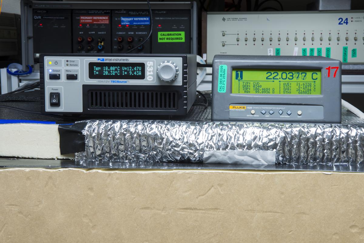
Measurement is taken by calibrated Fluke 1529 Chub-E4 thermometer + Omega RTDCAP-100 Pt100 sensor.
Next I've connected actual PID temperature controller, Arroyo 5310 (100W capable, 10A/12V unit) to 3 peltier elements (1 module) while second module with remaining 3 TECs set to constant 5W cooling by HP power supply (to avoid heatleak from outside). Arroyo TECsource controller has own temperature sensor, which is YSI 44006 precision thermistor in this case.
Usual RPi3 + Python app with
xDevs.com teckit open-source app was used to run a temperature sweep:

Settings for the run are below:
[testset]
mode                = none     ; Execute resistance delta measurement if delta3 or delta4 (H1-2182A), dsb_v for DSB-nV
all_test_disable    = false      ; Run bogus data if true
sv_start            = 17.400     ; Chamber start temperature
sv_end              = 17.400     ; Chamber end temperature
peak_temp           = 35.000     ; Top soak temperature
delay_start         = 0          ; Delay before any operation start, seconds
slope               = 8          ; Hours, Time for slope (symmetric positive/negative) ramp
time_start          = 2          ; Hours, Initial hold temperature time, before positive slope starts
time_dwell          = 1          ; Hours, Dwell temperature duration time at peak-start/2 temperatures
time_hold           = 8          ; Hours, Hold temperature duration time once reached peak_temp
time_end            = 2          ; Hours, Final temperature duration once rampdown finished
slope_shape         = lymex_step ; Advanced shape type, lymex_step = soak time_start in middle of the ramps
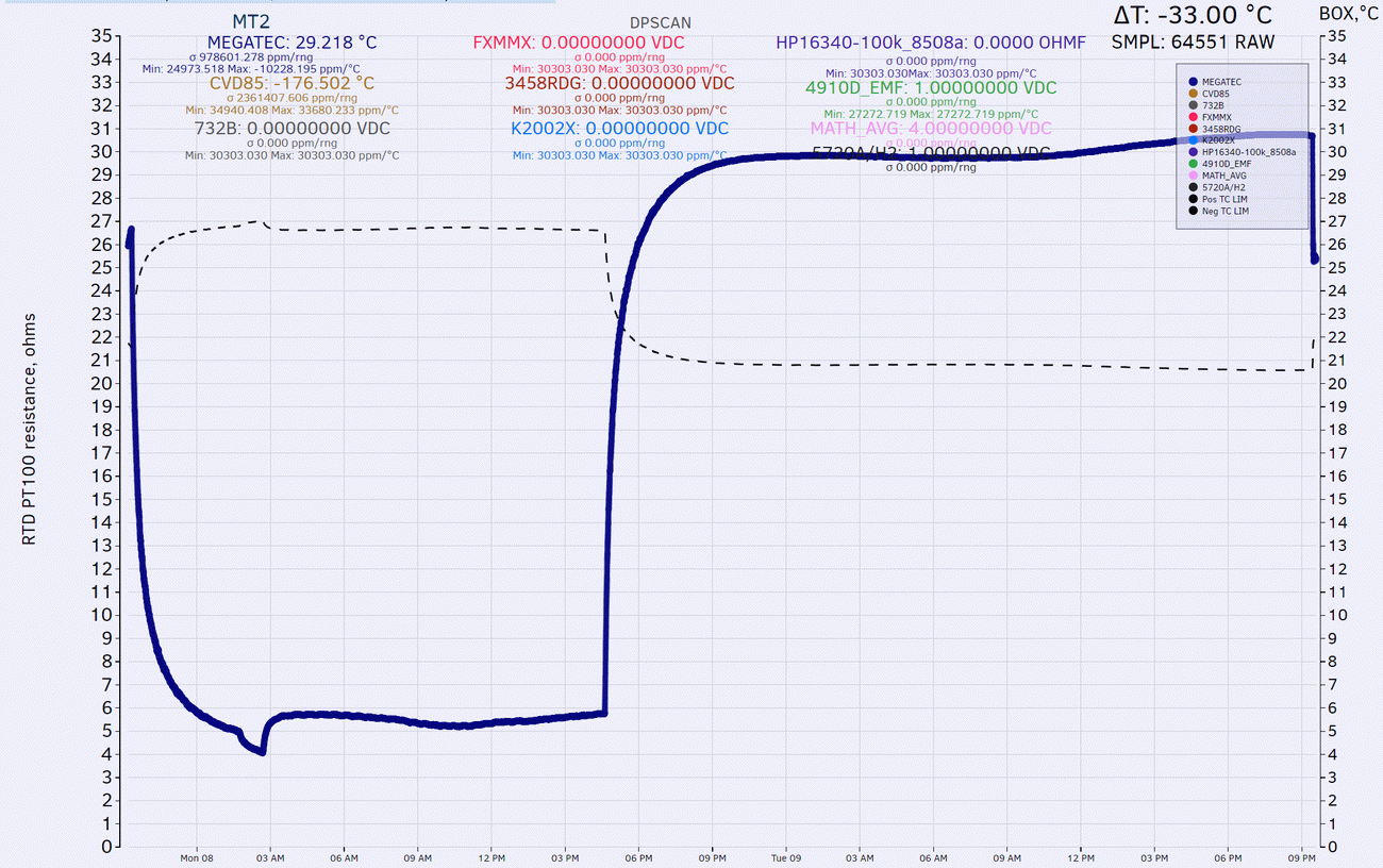
This will take about 30 hours to perform full sweep, from +17.4°C to +35.0 °C and back.
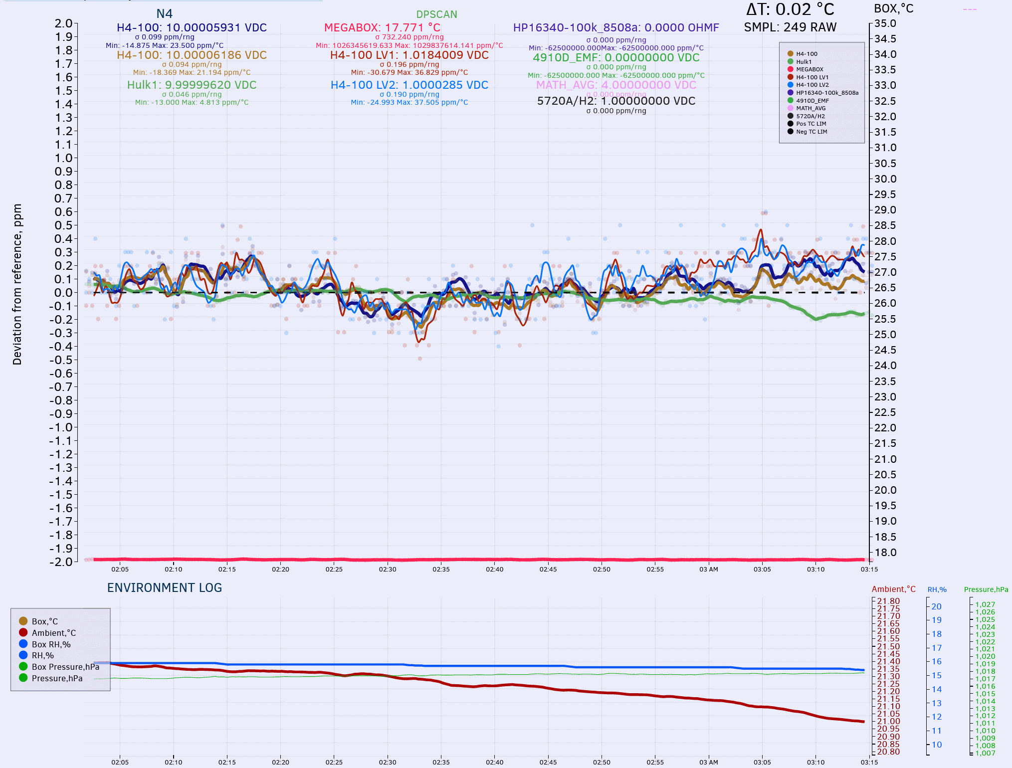
To make it more fun, I've put small low-power DC Voltage reference device inside the chamber and connected it's output to usual 3458A's and 34420A.
Measurement is taken by calibrated Fluke 1529 Chub-E4 thermometer + Omega RTDCAP-100 Pt100 sensor. You can see a sensor with blue tape at the body of the DUT.
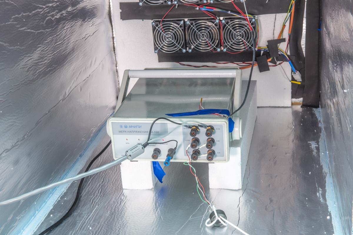
This reference is MNIPI N4-100 zener-based device, capable generating +10.000, +1.000 and +1.018 VDC. It is manufactured in 2006 in Belarus, and cost only $1700 USD MSRP so rather budget device (comparing to usual Fluke 732 stuff that is around $10k). N4-100's annual drift specified at unimpressive 4 ppm/year, despite being designed around Linear LTZ1000A super-zener chip.
It has option for custom 10 cell NiMH 24V battery pack but natively powered by mains, rated for 220VAC 50Hz. I don't have battery for it, so it is powered from my Chroma 61604 programmable AC source.
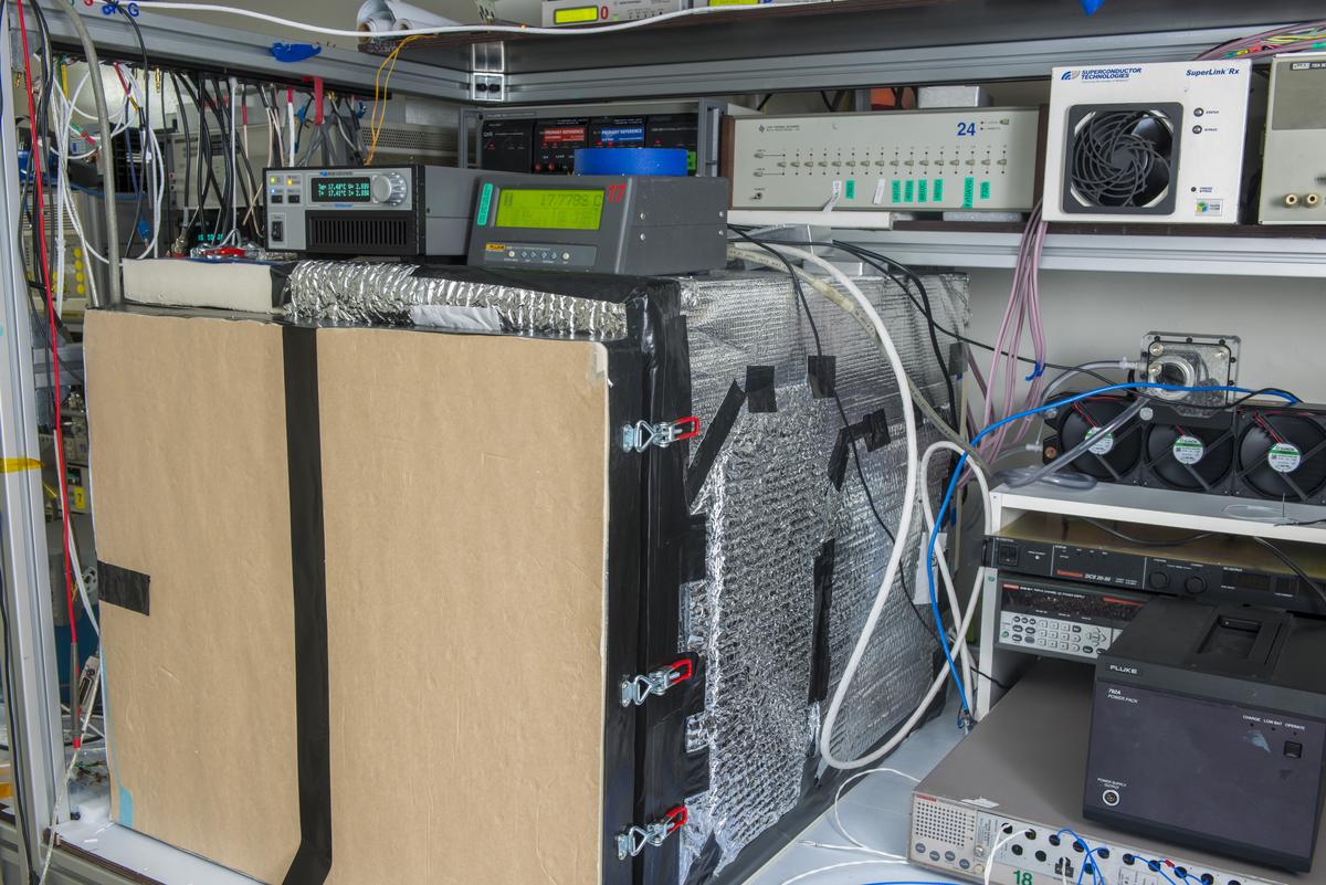
Overall view during benchmark:
Live data (clickable for interactive plot, updated every 5 minutes)