Author Topic: DIY Large thermal chamber for metrology T&M testing  (Read 26683 times)

0 Members and 1 Guest are viewing this topic.

Offline TiNTopic starter

  • Super Contributor
  • ***
  • Posts: 4543
  • Country: ua
    • xDevs.com
DIY Large thermal chamber for metrology T&M testing
« on: February 21, 2021, 06:59:56 am »
Previous DIY TEC chamber, revision 2018

Over last 6 years multiple small size insulated thermal chambers were build for xDevs.com's projects.

Peltier heat pump was used as active element to provide both cooling and heating capability.

Previous design from 2018-2020 years successfully used for various LTZ1000A voltage reference and small resistance (such as Fluke 742A) standards temperature tests. It was using 40W single-stage TEC element, closed-loop watercooling pump+HX and copper heatsink as thermal exchanger.
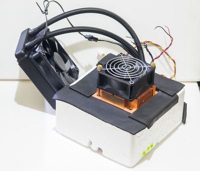
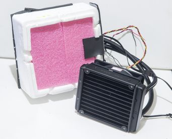
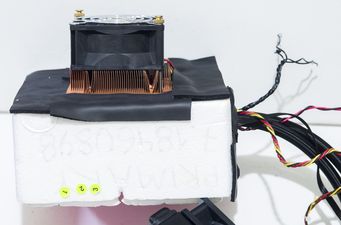
80 mm fan installed on thermal chamber to actively mix air within insulated chamber. This helped to obtain uniformity better than 0.2 °C when passive or <5W active devices are used in chamber as DUT.

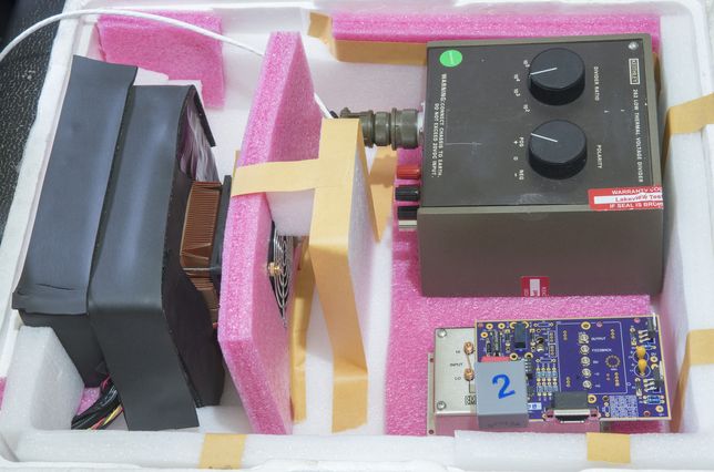
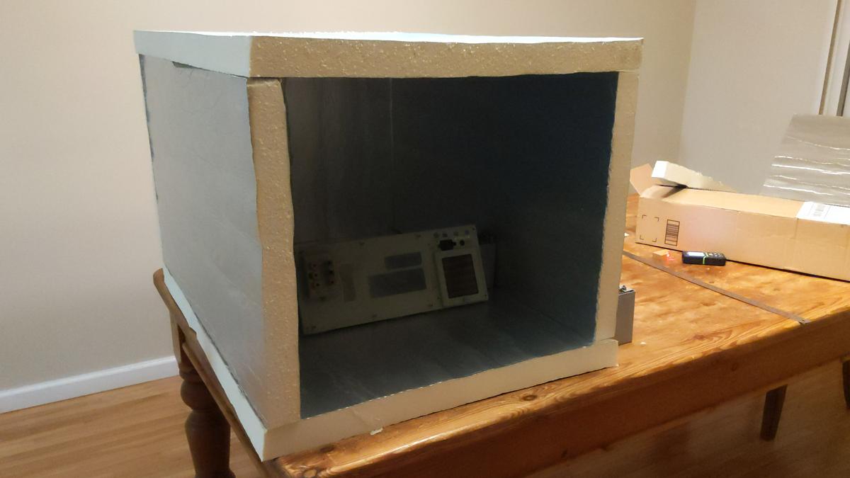
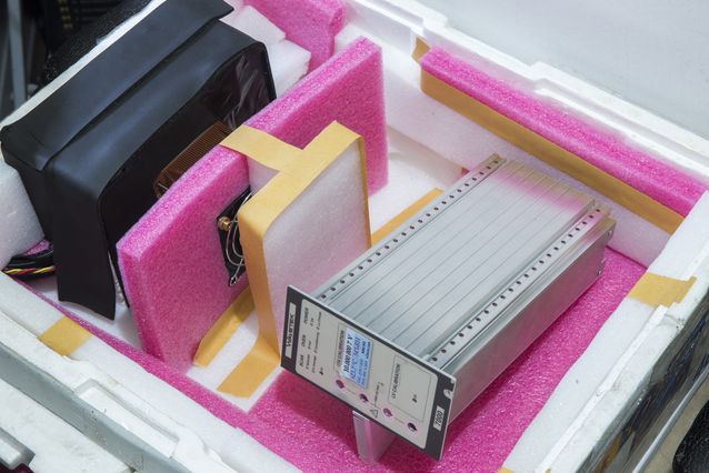
Components layout in the larger Styrofoam box for better thermal ambient insulation shown on photos below.
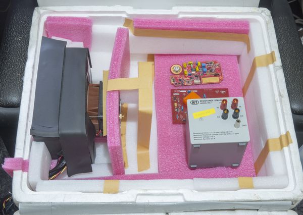
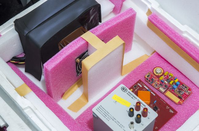

Device under test examples, such as Wavetek 7000 DC voltage reference and Keithley 262 + EM A10 nanovolt amplifier were tested using this chamber.


This chamber also tested with Arroyo TECPak 585 to perform multiple hour sweep with slow temperature ramp. Temperature and data acquisition was controlled by xDevs.com's teckit open-source application.
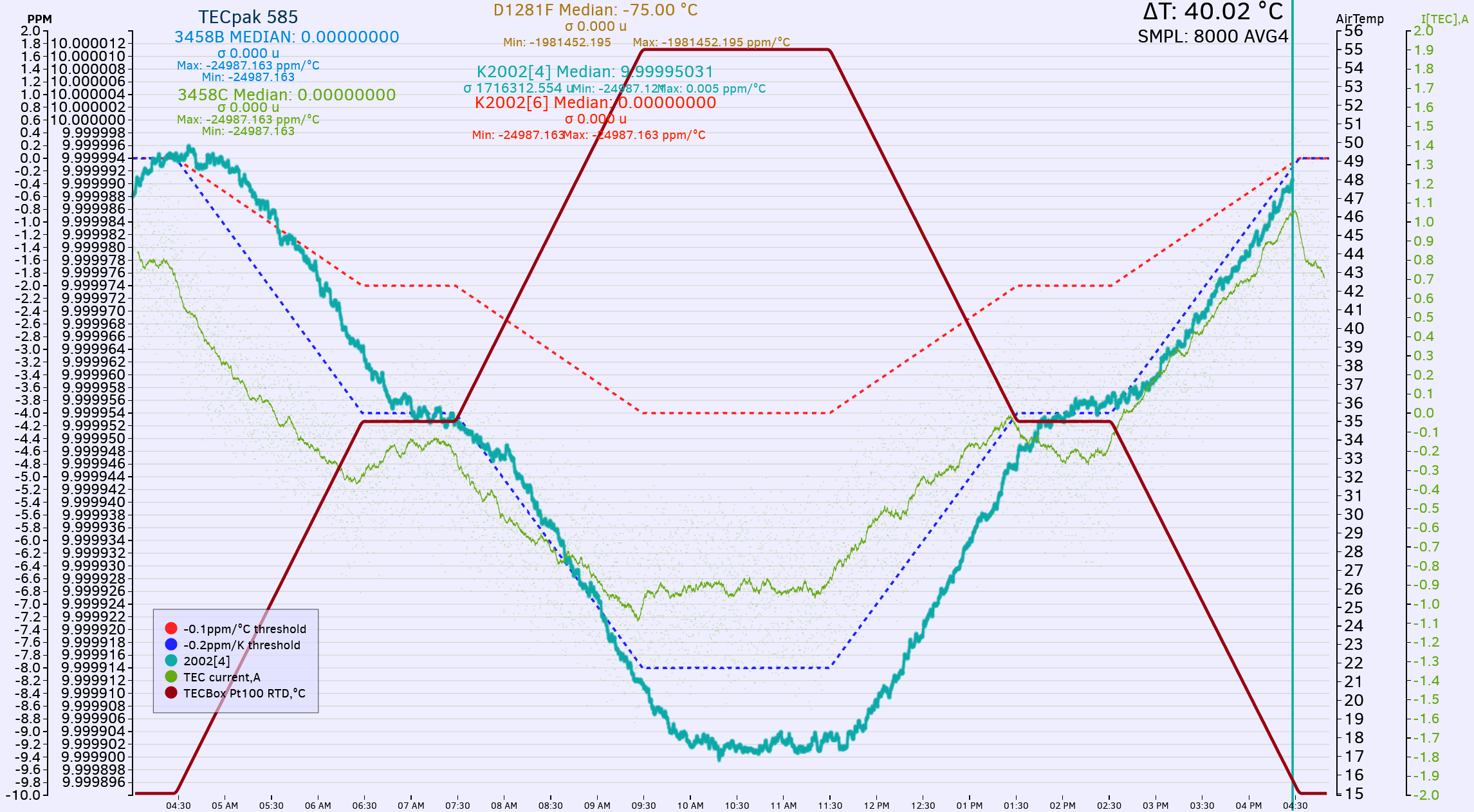


First plot shows controlled temperature ramp from +15.0 °C to +55 °C with intermediate soak time at half-scale, +35 °C. Changing temperature by 40 °C allow us to evaluate temperature coefficient (stability) of IanJ's PDVS2 mini with good resolution and confidence. In this case voltage dropped from 9.999994 VDC to 9.999902 VDC.

Overall time for this ramp was 12 hours, with ramp speeds 0.125 °C/minute. Now lets zoom in and look into middle step flat section:
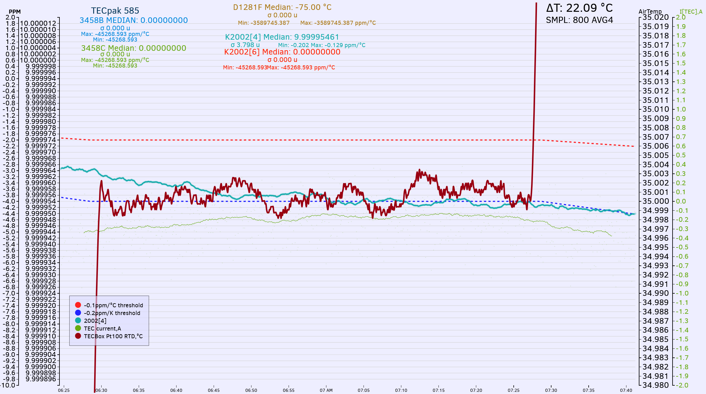


Temperature axis rescaled to much finer resolution here, at 0.001 °C per division. Arroyo TECPak provided nice and stable control, with variations of temperature readout less than +/- 0.003 °C during step time 1 hour.

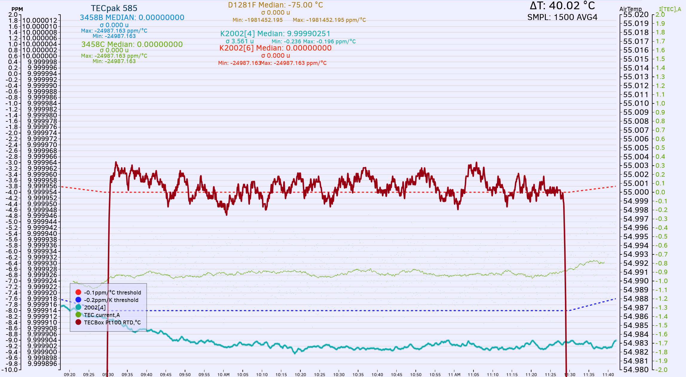
Next plot shows 2 hour step at peak +55 °C temperature. Again, no problems or overshoots, while maintaining +/-0.004 °C temperature stability.


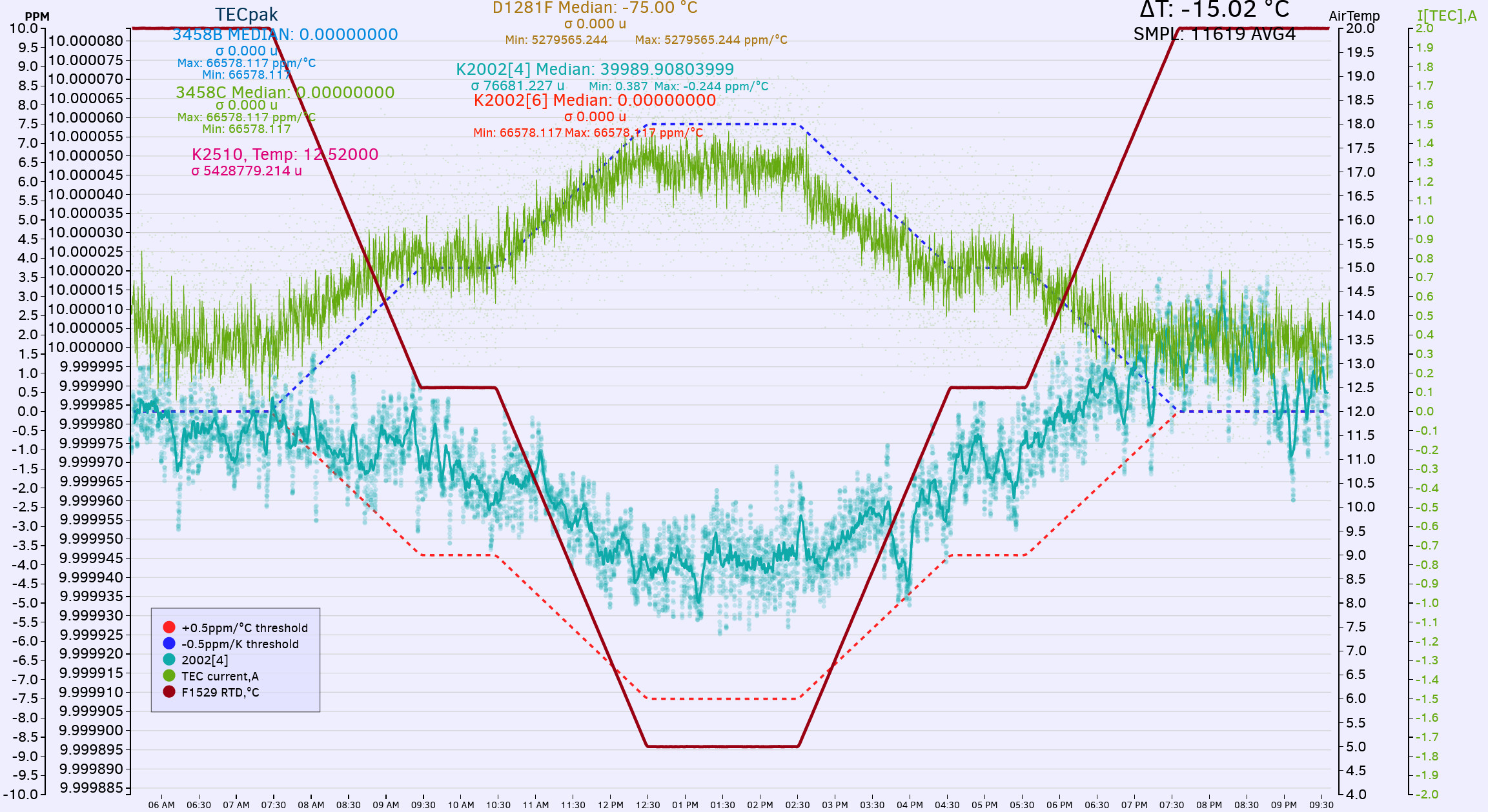
Opposite test with going sub-ambient temperatures, with ramp from +20 °C to +5 °C during 15 hour test.


New MEGA TEC chamber, revision 2021

But I always wanted to have ability of testing larger devices, such as full size 19" DMM (Keysight 3458A, Fluke 8508A and alike). Ideally chamber should also support even bigger and heavier devices, such as multi-function calibrator Fluke 5720A or Datron 4808.

However testing such active instruments is not practical or possible with low power 40W Peltier TEC. This is problem for next monster chamber project aimed to solve.

After checking available space on bench and targeted use cases next feature set was established as target:

* Big enough to fit 5720A+5725A and 3458A or multiple 732A
* 850 x 600 x 500 mm inner volume
* High power TEC module assembly to allow fast control, to support max 900W active load inside chamber
* Desired temperature range from 0 °C to +60 °C
* Temperature uniformity better than 0.1 °C
* Temperature stability better than 0.05 °C with heat load <50 W
* Temperature stability better than 0.1 °C with heat load 500 W
* Watercooling loop for TECs to allow uniform 50-100mm isolation from ambient
* Ambient influence less than 0.01 °C/°C
* Possibility for humidity control?
* Possibility for pressure control?
* Easy removable front door\lid to allow DUT management
* Material BOM cost less than $500 USD

Dow Super TUFF-R R-13 foam faced board was used as a starting point to provide robust thermal insulation. Two sheets were acquired from local Home Depot store

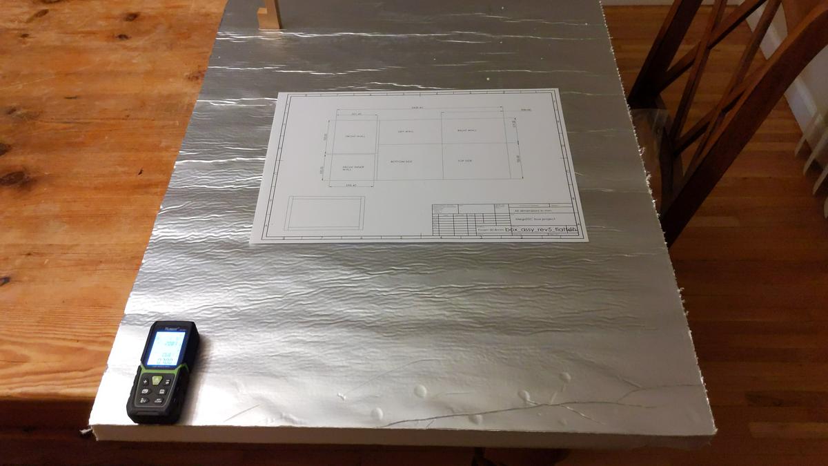
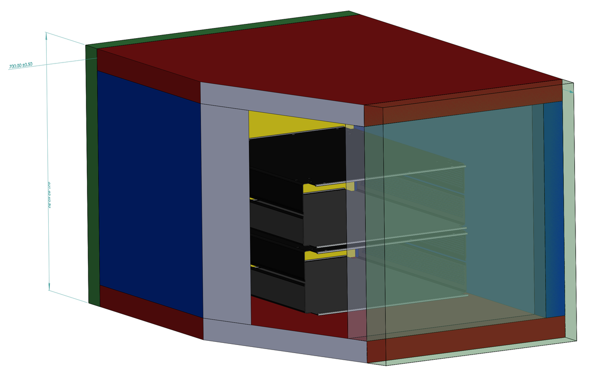
Simple CAD was sketched together with dimensions in mind to fit all parts on a 1.25 sheets.


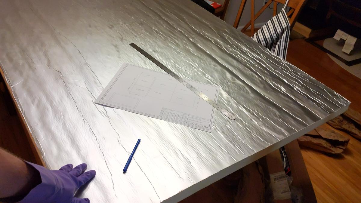
How let's cut board to pieces and start layout


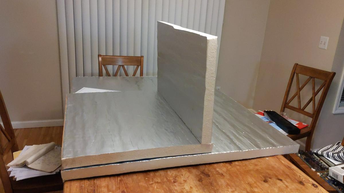
We can use random 8½-digit DMM (Advantest R6581T) to demonstrate available room in chamber.
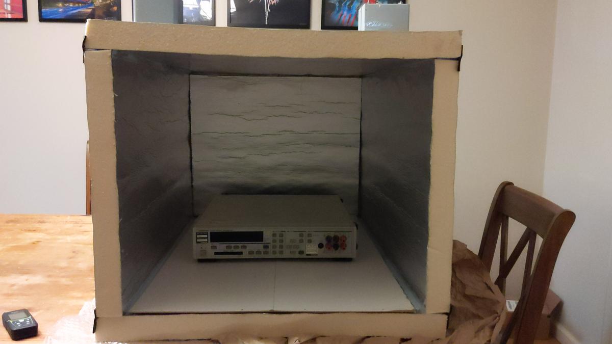


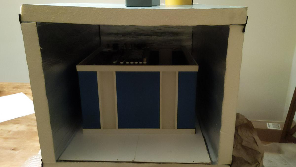
Even bigger devices, such as ESI 242D resistance system could fit in chamber. Sideways only  :-DD

However main goal to fit 5720A+5725A+3458A is met.


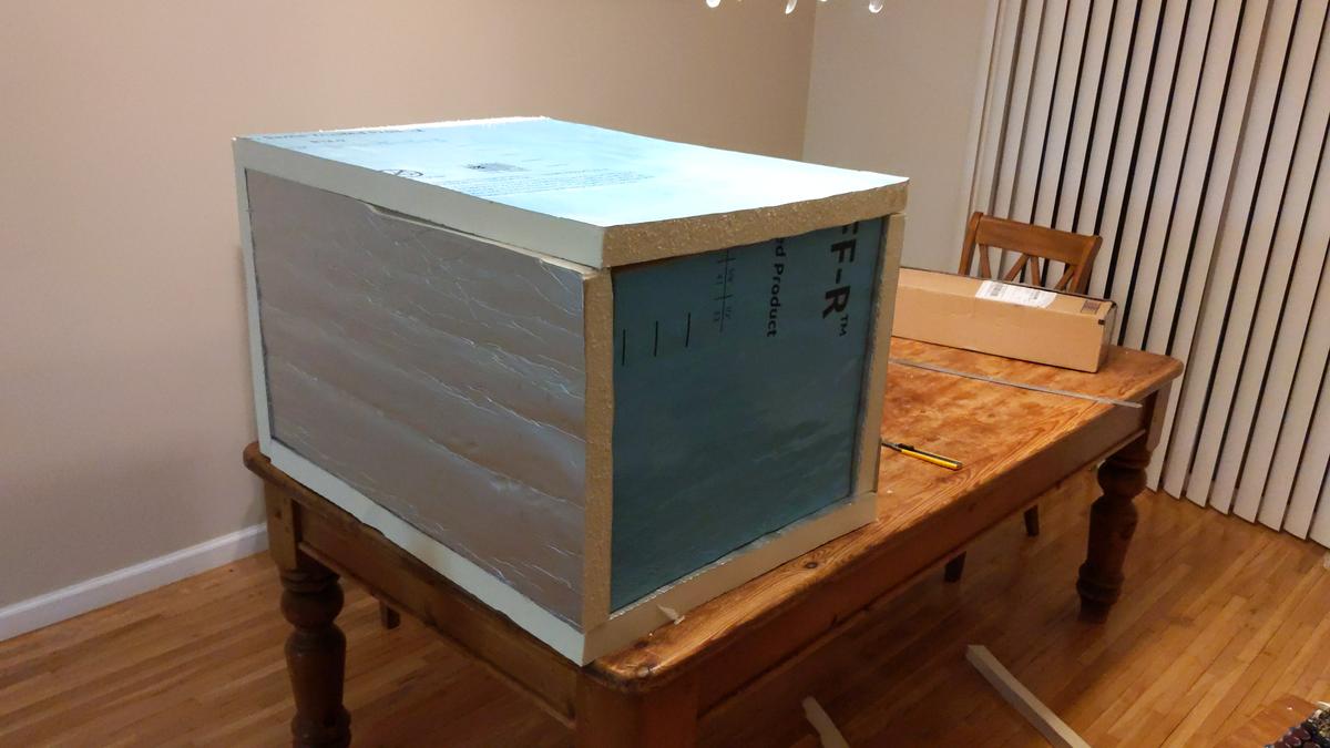
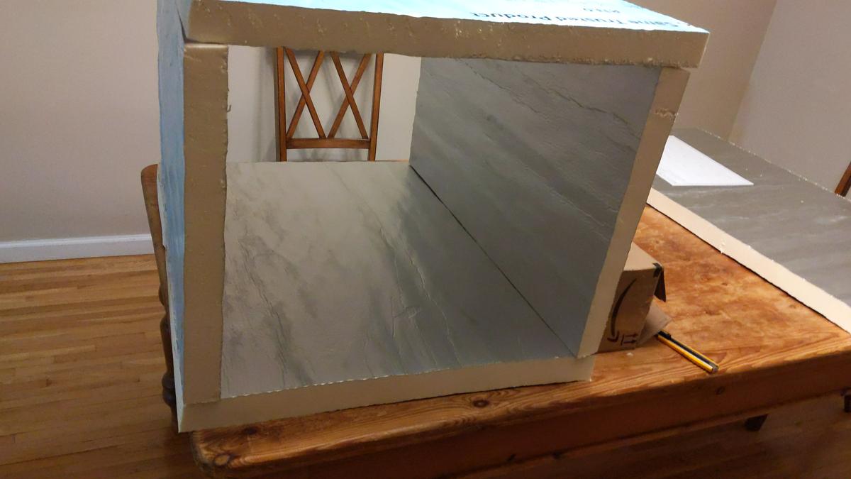
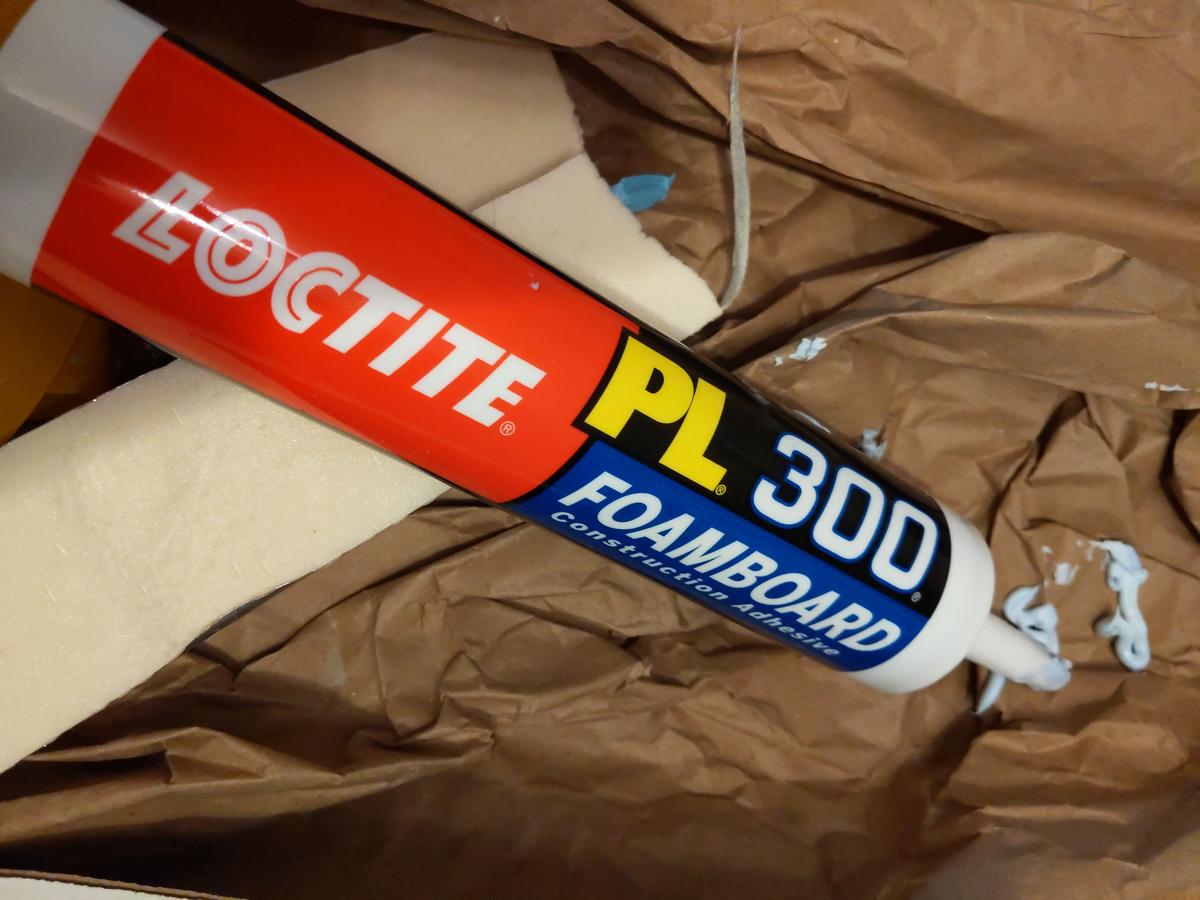
Looking pretty good, time to glue the edges on all walls and attach them to base sheet. Special Loctite PL300 latex-based foam-board glue was used to ensure good adhesion to foam wall. Full curing time of this glue is 7 days.

It is designed to be operated in temperature range from -17.7 to +77 °C. This is good enough for our design target.
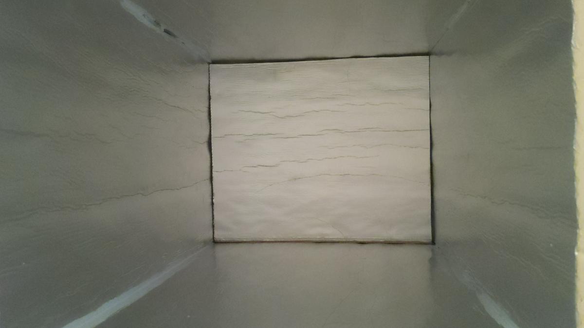
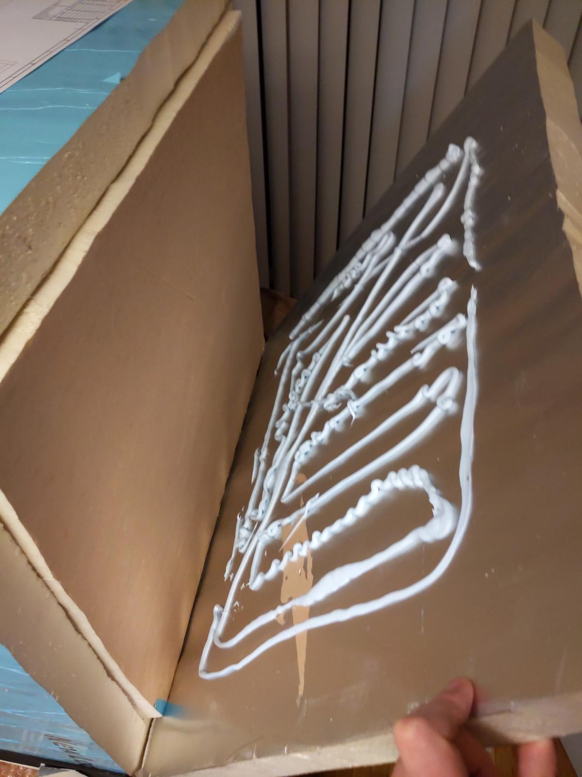
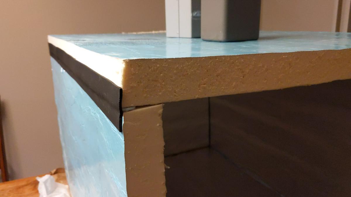


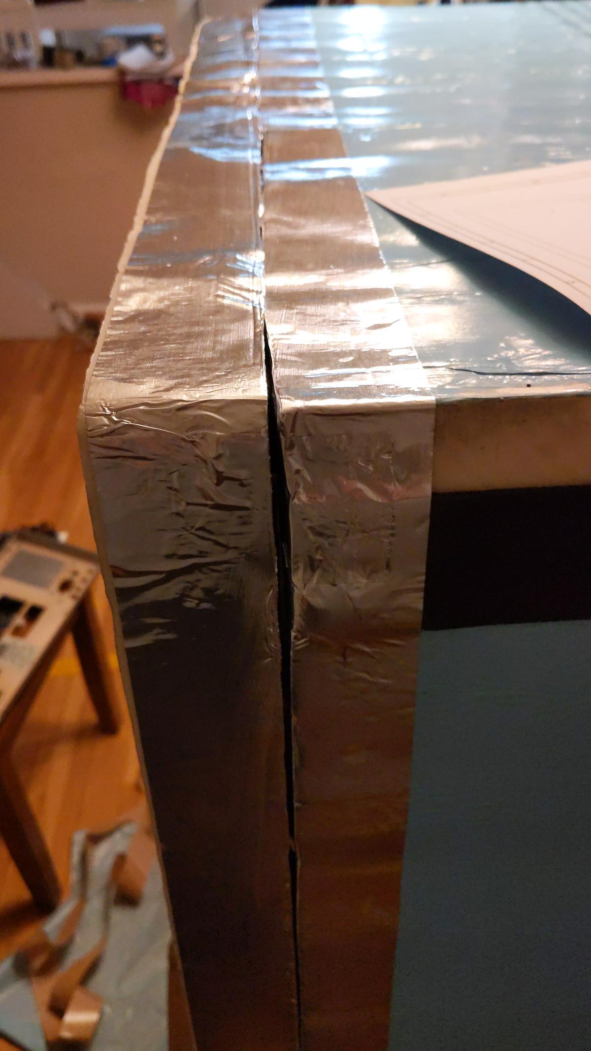
Foam is relatively easy to deform, so to improve reliability and better practical use edges faced with aluminum thin foil. In final use there will be also sealing gasket around the front and rear lids to ensure air-tight seal during chamber operation.
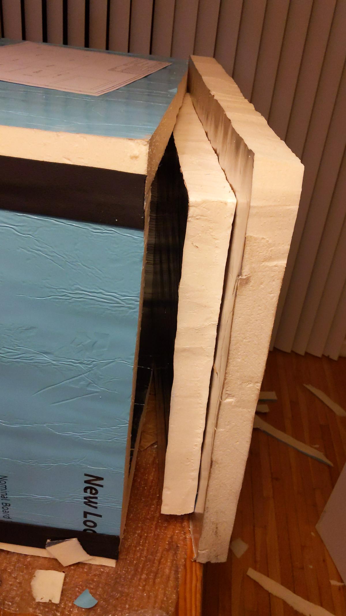
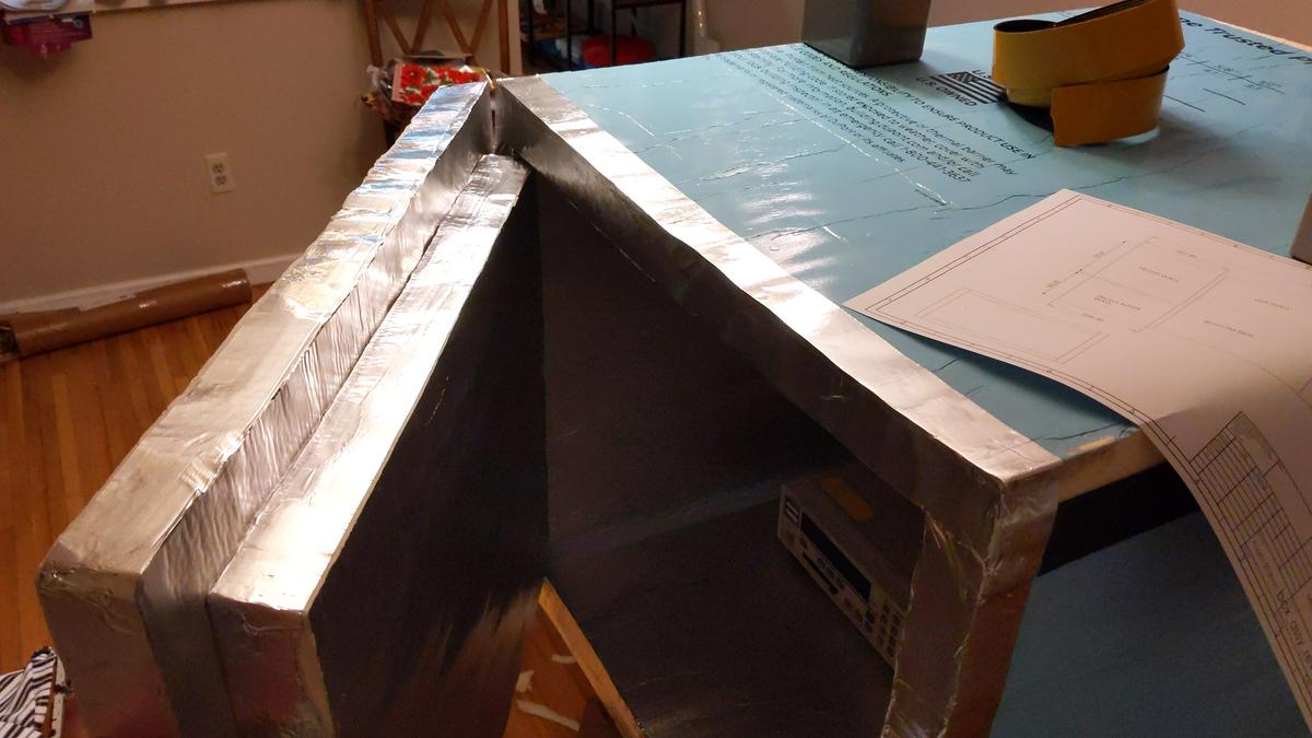


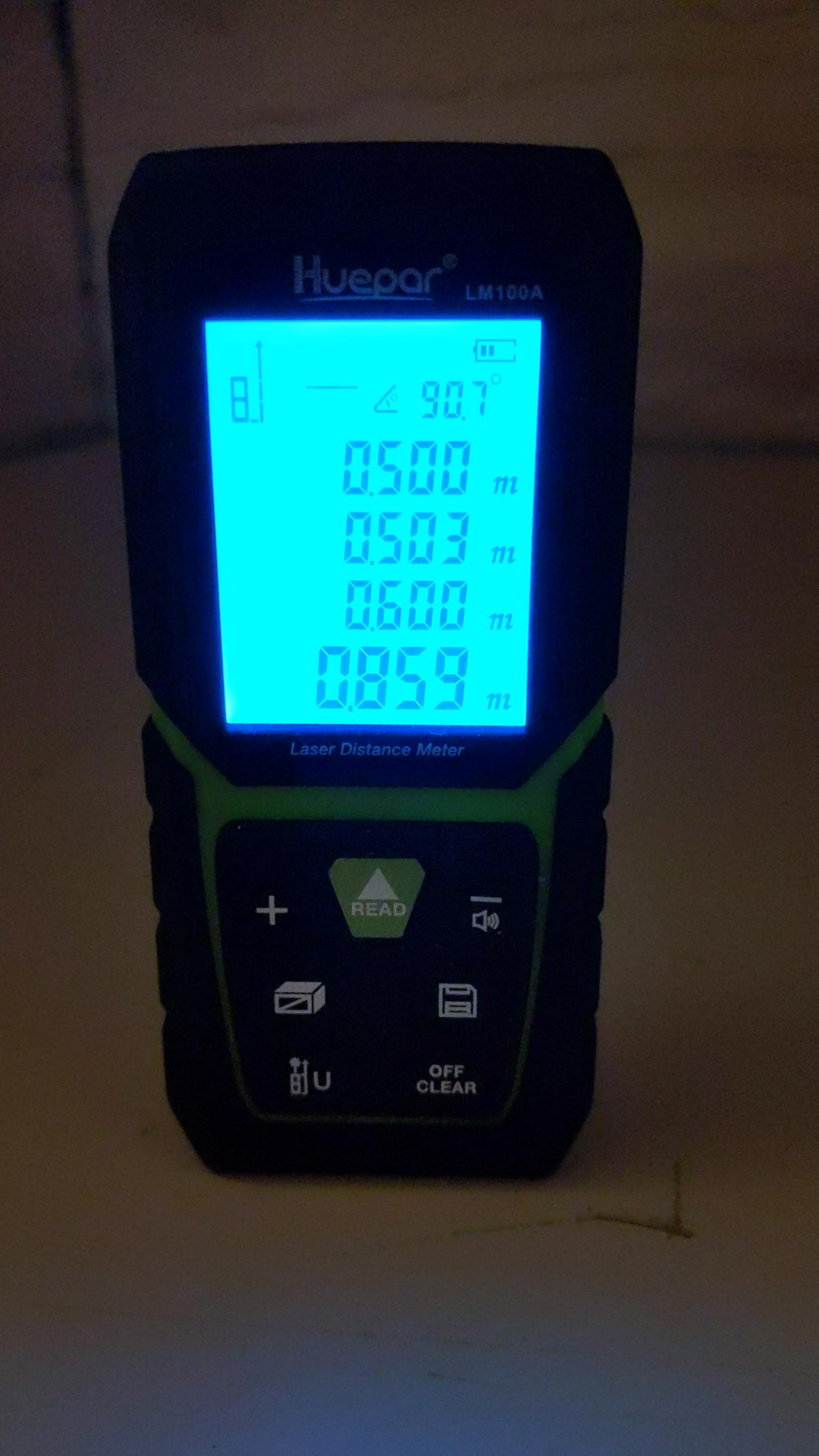
Inner dimension requirements are also met:


<h3>First test</h3>

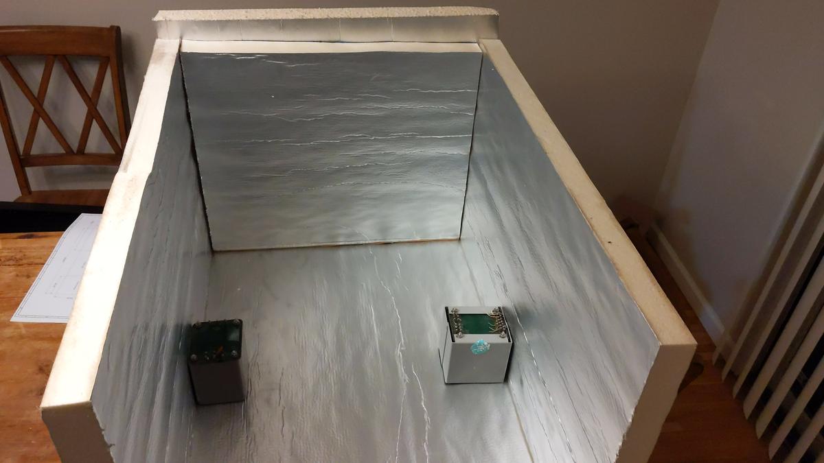
As chamber is curing, I've put old electronics and decided to run a 132 hour sweep from +38°C to +5°C and back with help of only 40W TEC module. This will give initial idea if such large chamber concept on the right track.
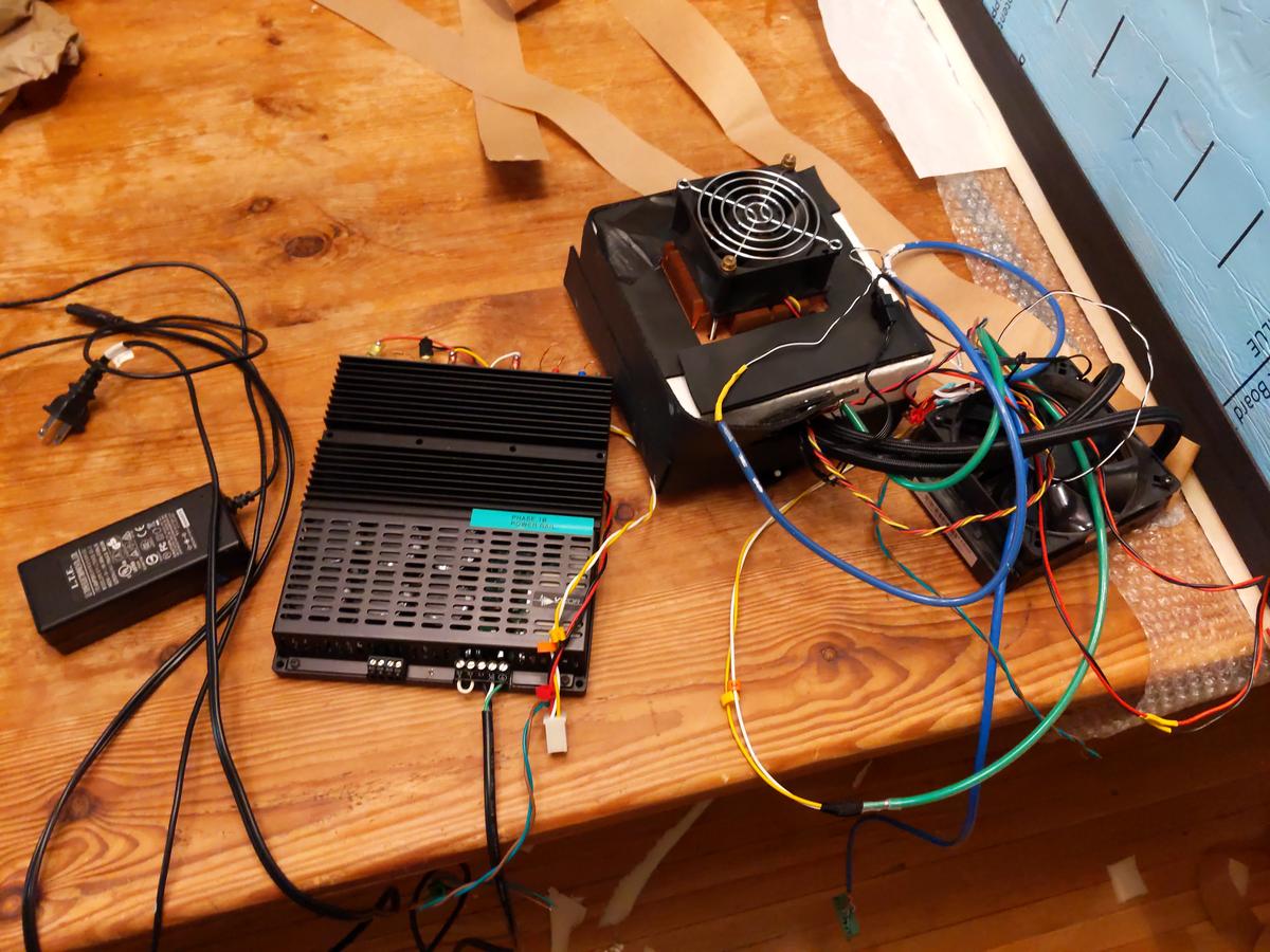


Vicor AC-DC supply provides +12V for watercooling pump/radiator fan and +6V for inner chamber mixing air fan.
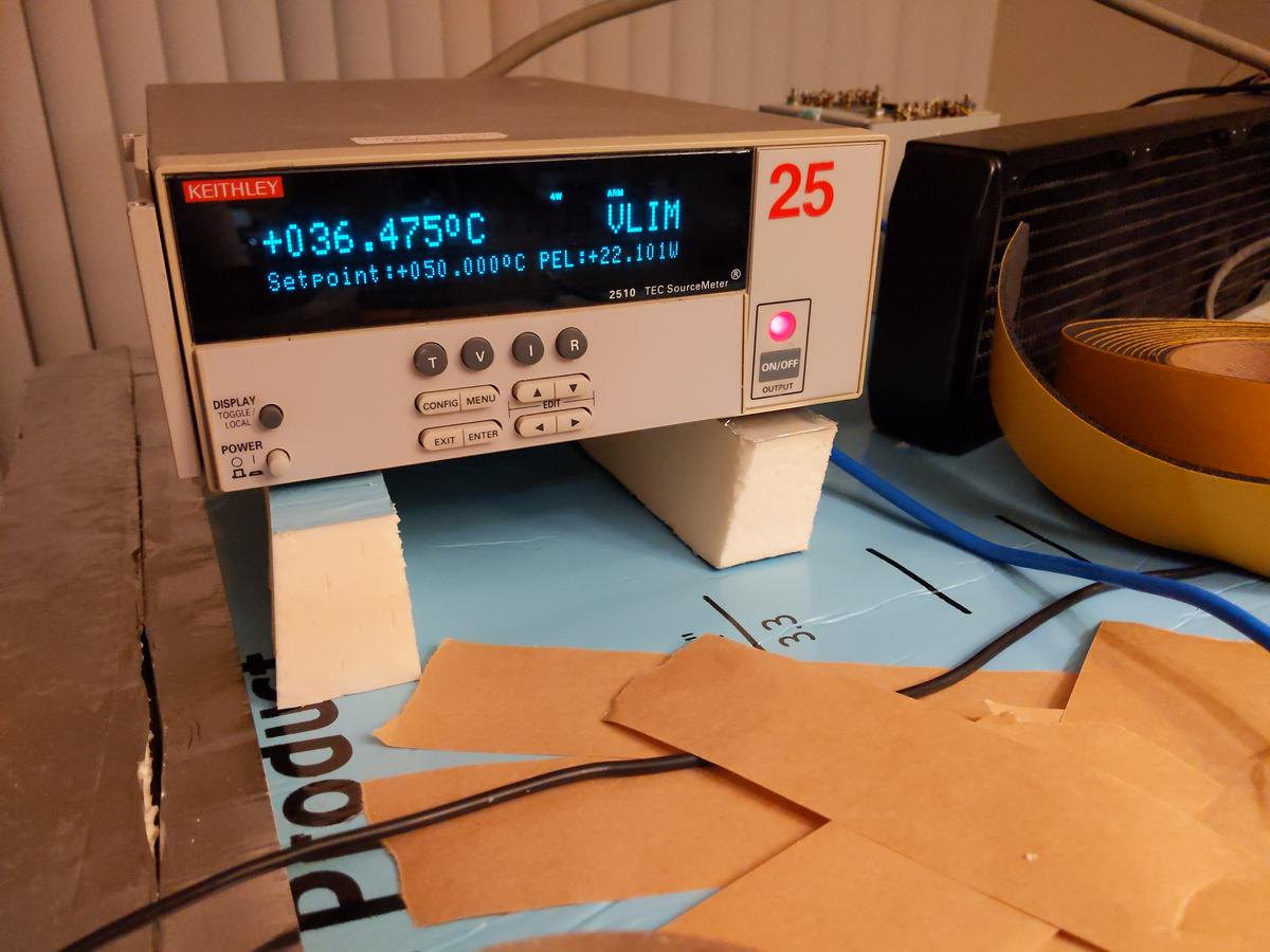


Good old Keithley 2510 TEC SMU was used as temperature PID-controller.
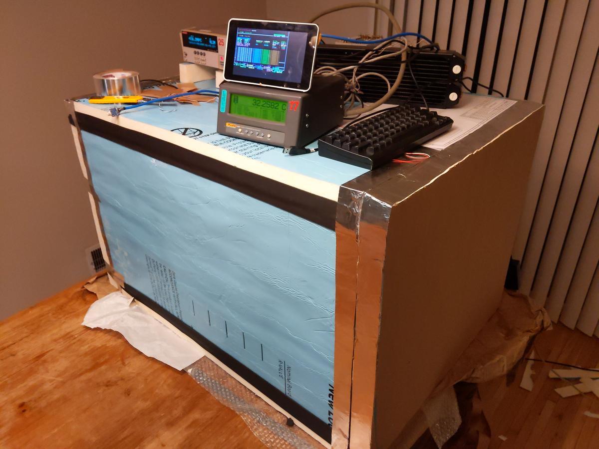


Additional measurement was also taken with calibrated Fluke 1529 Chub-E4 + Omega RTDCAP PT100 sensor.
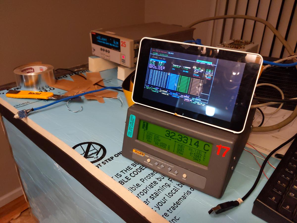


Raspberry Pi 3 used to run teckit application and store measurement results into DSV-file.

To be continued...
« Last Edit: February 21, 2021, 07:11:57 am by TiN »
YouTube | Metrology IRC Chat room | Let's share T&M documentation? Upload! No upload limits for firmwares, photos, files.
 

Offline Vgkid

  • Super Contributor
  • ***
  • Posts: 2710
  • Country: us
Re: DIY Large thermal chamber for metrology T&M testing
« Reply #1 on: February 21, 2021, 09:12:42 am »
I look forward to seeing this build.
If you own any North Hills Electronics gear, message me. L&N Fan
 

Offline nfmax

  • Super Contributor
  • ***
  • Posts: 1560
  • Country: gb
Re: DIY Large thermal chamber for metrology T&M testing
« Reply #2 on: February 21, 2021, 09:18:07 am »
If you are using large equipment in such a chamber, you should support it on a grid or wire shelf off the base, so the internal fan can circulate air over all surfaces, including the equipment bottom panel.
 
The following users thanked this post: TiN

Offline Kleinstein

  • Super Contributor
  • ***
  • Posts: 14197
  • Country: de
Re: DIY Large thermal chamber for metrology T&M testing
« Reply #3 on: February 21, 2021, 10:10:54 am »
For the base I would consider a aluminium plate. This helps to get a uniform temperature also under the instrument and it could help to mount supply cables (likely some 110 V outlets). Heat transfer via cables could than first go to the relatively large plate.

High powert thermoelectric cooling comes at the price of quite some thermal path to the outside, even of the full power is not needed. The thermal conductivity of the TEC elements is relatively high. Less powerful cooling would allow for better isolation. 

One could consider a modular form so that one could reduce the number of TEC elements depending on the power requitements. Another option may be to use a kind of 2 stage operation for the rare cases were one needs low temperature at relatively high power  - up to the point of using ice cubes to cool the outside of the TECs in this case. This way one could use less TEC elements, which would help normal use with lower power.

If more power is needed for heating, just additional pure heaters may be easier than additional TECs. So the TEC part would mainly need to be designed for cooling - heating would likely be sufficient anyway and if no it is easy to add extra heaters. 
 

Offline TiNTopic starter

  • Super Contributor
  • ***
  • Posts: 4543
  • Country: ua
    • xDevs.com
Re: DIY Large thermal chamber for metrology T&M testing
« Reply #4 on: February 21, 2021, 04:10:23 pm »
Quote
High powert thermoelectric cooling comes at the price of quite some thermal path to the outside, even of the full power is not needed

Can you explain a bit more? Only heat interface between outer world and inner volume are wires and two silicon pipes with coolant for TEC HX. TEC module will be mounted on the rear lid which is 101.6 mm thick (two layers of foam board).

All tubing inside and TEC "hot side" will be insulated in armaflex foam as well.
YouTube | Metrology IRC Chat room | Let's share T&M documentation? Upload! No upload limits for firmwares, photos, files.
 

Offline Kleinstein

  • Super Contributor
  • ***
  • Posts: 14197
  • Country: de
Re: DIY Large thermal chamber for metrology T&M testing
« Reply #5 on: February 21, 2021, 05:27:53 pm »
The TEC module itself has thermal conduction between the sides. In the usual model for a TEC there is this thermal conduction, the peltier effect proportional to the current and the resistive loss given by resistance times current squared. The internal thermal conduction is what limits the maximum temperature difference. So one can quite easy calculate the internal thermal conduduction as maximum power (at zero temperature difference) divided by maximum temperature difference.  With a typical max. temperature difference of a little below 50 K and some 500 W of intendent max power this would be some 10 W/K, which is a pretty strong thermal coupling.
 

Offline TiNTopic starter

  • Super Contributor
  • ***
  • Posts: 4543
  • Country: ua
    • xDevs.com
Re: DIY Large thermal chamber for metrology T&M testing
« Reply #6 on: February 21, 2021, 06:10:57 pm »
Yes, but wouldn't it be compensated by temperature regulation loop?
So whatever heat/cold lost due to transfer between sides of TEC would be compensated by controller.  :-//
YouTube | Metrology IRC Chat room | Let's share T&M documentation? Upload! No upload limits for firmwares, photos, files.
 

Offline Kleinstein

  • Super Contributor
  • ***
  • Posts: 14197
  • Country: de
Re: DIY Large thermal chamber for metrology T&M testing
« Reply #7 on: February 21, 2021, 06:26:03 pm »
The controller would still act against the heat loss, but the regulator has only a limited faktor to suppress external heat flow (e.g. some 0.01K/K as the target).
External disturbance can also effect the outside of the TEC and this way get a relatively fast path to the inside. With fewer TEC modules the controller would have a chance to get better suppression of external temperature variations, as it would see less disturbance in the heat flow.

One can in principle measure the temperature of the hot side and include this in the regulation. This way one could compensate much of the heat going this path in a feed forward manner instead of the regulator. This could to a large part compensate the extra heat path. However not many ready made conterlers include this function - it would not be a big deal with a DIY controller.

Less TEC elements would also save on the costs.
 

Offline Vtile

  • Super Contributor
  • ***
  • Posts: 1144
  • Country: fi
  • Ingineer
Re: DIY Large thermal chamber for metrology T&M testing
« Reply #8 on: February 21, 2021, 07:20:39 pm »
Pssst. 200 L box freezer....
 
The following users thanked this post: SilverSolder, DC1MC

Offline TiNTopic starter

  • Super Contributor
  • ***
  • Posts: 4543
  • Country: ua
    • xDevs.com
Re: DIY Large thermal chamber for metrology T&M testing
« Reply #9 on: February 21, 2021, 07:22:35 pm »
Outside of the TEC? Whole TEC assembly with cooling waterblock are inside of the chamber.

Either way, here's first plot, still using 40W watercooled TEC from old setup.


While result is mediocre versus desired spec, it is actually better than I have expected.
Distance between remote RTD sensor and control RTD is about 50cm inside chamber.

Major drawback of large volume is slooow response, so that will be investigated in future once I get more powerful TEC setup and angry fans to mix air faster.

Also visible how ambient air temperature variation due to central heating cycles about 1°C cause control temperature inside chamber change ~0.1°C. So we need better insulation :)
« Last Edit: February 21, 2021, 07:38:15 pm by TiN »
YouTube | Metrology IRC Chat room | Let's share T&M documentation? Upload! No upload limits for firmwares, photos, files.
 

Offline Anders Petersson

  • Regular Contributor
  • *
  • Posts: 122
  • Country: se
Re: DIY Large thermal chamber for metrology T&M testing
« Reply #10 on: February 21, 2021, 07:42:31 pm »
Very interesting project.
I'd like to know more how you decide on how many TECs and which models to use, and how you plan to distribute the heating/cooling effect evenly throughout such a large volume.

My own attempt uses a complex design with an inner and an outer chamber for max temperature uniformity. I've only done initial testing yet, with mixed results.
 
The following users thanked this post: lowimpedance, TiN, Kean

Offline nfmax

  • Super Contributor
  • ***
  • Posts: 1560
  • Country: gb
Re: DIY Large thermal chamber for metrology T&M testing
« Reply #11 on: February 21, 2021, 07:46:02 pm »
A useful reference for this sort of thing is the 'missing' chapter 20 on thermal control, from Philip Hobbs's book:

ftp://ftp.wiley.com/public/sci_tech_med/electro-optical/thermal.pdf
 

Offline TiNTopic starter

  • Super Contributor
  • ***
  • Posts: 4543
  • Country: ua
    • xDevs.com
Re: DIY Large thermal chamber for metrology T&M testing
« Reply #12 on: February 21, 2021, 07:53:09 pm »
Anders Petersson
If you can share your results, perhaps would be interesting to relate. In smaller volumes it is much easier to obtain uniformity, than large ones, especially with active heat sources inside.
So far I plan to use row of high speed fans that can cycle all inner air volume within few seconds.

I've bought 3xTEC cheap module to experiment:


This is next step :)
« Last Edit: February 21, 2021, 07:57:42 pm by TiN »
YouTube | Metrology IRC Chat room | Let's share T&M documentation? Upload! No upload limits for firmwares, photos, files.
 

Offline Kleinstein

  • Super Contributor
  • ***
  • Posts: 14197
  • Country: de
Re: DIY Large thermal chamber for metrology T&M testing
« Reply #13 on: February 21, 2021, 07:59:53 pm »
This looks like an interesting design - a bit like a wind tunel.

To decide one the number of TECs needed, the cooling part should be relevant (extra heating is easy and could use simple resistors instead of TECs). Based on DUT power and heat losses / isolation one can estmate the required power and required number of TECs.  At 1/2 the maximum temperature difference one may get something like 1/4 to nominal power. So don't get fooled by the nominal power rating - this is for zero difference. For best efficiency the current would be reduced and thus an even smaller power. This may not be econimic, but I would still plan with some 20% below nominal current, as heat sink qualitiy is less than perfect and the last bit of current mainly helps at high temperaure difference.

This also shows that cooling the ouside (especially for peak power needs) or at least a very efficient heat sink really helps. Reduce the temperature difference from some 25 K to 5 K would allow something like 4 times the cooling power per element or getting away with 1/4 the elements.
 

Offline Anders Petersson

  • Regular Contributor
  • *
  • Posts: 122
  • Country: se
Re: DIY Large thermal chamber for metrology T&M testing
« Reply #14 on: February 21, 2021, 08:22:44 pm »
TiN, so far I only tested the lowest temperature I could reach with 500W spread over 12 TECs and I was disappointed. I'll share in a separate thread when I have more results.

In my case, I suspect that the fan motor adds significant heating to the chamber. That might not be a problem in your scenario, but do include the fans in your heat flows budget calculation. The design pictured uses a single 180mm fan with the reasoning that a large fan is more efficient than small ones. But the narrow air channels of the design (see attachment) probably restricts the flow since I see poor air flow with anything less than full fan speed. I think this is due to the low static pressure rating of this type of fan.
I'm now looking into driving the fan with a motor outside the chamber, via a custom shaft. The problem has been aligning the moving parts with enough precision to avoid lots of vibration.
 

Offline Anders Petersson

  • Regular Contributor
  • *
  • Posts: 122
  • Country: se
Re: DIY Large thermal chamber for metrology T&M testing
« Reply #15 on: February 21, 2021, 08:30:24 pm »
TiN, your 3x TEC module looks fit for the purpose, though I'm not sure you can cool as cold as you want. (Unless you do as I and use ice water as coolant.)

What I'm doing is to connect the water blocks in parallel instead of in series, using T connections to a wider tube. The idea is to restrict the flow less and avoid cooling the next water block with water heated from the previous one. I don't know yet what difference this makes -- I will measure water temperature to learn more.
 

Offline TiNTopic starter

  • Super Contributor
  • ***
  • Posts: 4543
  • Country: ua
    • xDevs.com
Re: DIY Large thermal chamber for metrology T&M testing
« Reply #16 on: February 21, 2021, 08:32:49 pm »
I'd expect thermal gradients on your metal plates are much bigger issue than a fan airflow.
Usual approach is to maximize surface area for heat exchangers, so there is more air in contact with cold surfaces.

In this project I don't do much science and math to calculate all details, it's more hands-on "let's build something and see how bad it is" instead of careful modelling of heatflow and physics. After all this is all hobby project, not a business application.
YouTube | Metrology IRC Chat room | Let's share T&M documentation? Upload! No upload limits for firmwares, photos, files.
 

Offline jbb

  • Super Contributor
  • ***
  • Posts: 1143
  • Country: nz
Re: DIY Large thermal chamber for metrology T&M testing
« Reply #17 on: February 21, 2021, 11:39:34 pm »
You know, if someone’s feeling particularly cunning it is possible to make heat pipes without internal wicks, which will only conduct heat up. That can make a thermal diode, so theoretically half the Peltier elements could sit on the ‘cathode’ of a thermal diode and only provide cooling as required.

(Note, water is often used as a working fluid in the heat pipes so temperature needs to remain above 0 deg C.)
 

Offline TiNTopic starter

  • Super Contributor
  • ***
  • Posts: 4543
  • Country: ua
    • xDevs.com
Re: DIY Large thermal chamber for metrology T&M testing
« Reply #18 on: February 22, 2021, 03:12:45 am »
Sounds complicated... I do not have access to metal working shop / machining / lathe etc to mess with stuff like heatpipes.

Received Edwards E2M8 vacuum pump for future pressure chamber experiments. I expected it to be somewhat smaller, but its quite a hefty 24 kg monster.
Gotta learn a bit about vacuum gear and buy more accessory like oil mist filter, KF25 flange adapters, pressure valve ports, solenoid valves, etc.. But that's a story for another time, not a current priority for thermal chamber work.

YouTube | Metrology IRC Chat room | Let's share T&M documentation? Upload! No upload limits for firmwares, photos, files.
 

Offline jbb

  • Super Contributor
  • ***
  • Posts: 1143
  • Country: nz
Re: DIY Large thermal chamber for metrology T&M testing
« Reply #19 on: February 22, 2021, 05:48:43 am »
Sounds complicated...

Received Edwards E2M8 vacuum pump ... buy more accessory like oil mist filter, KF25 flange adapters, pressure valve ports, solenoid valves, etc...

:D
 

Offline Kean

  • Supporter
  • ****
  • Posts: 2092
  • Country: au
  • Embedded systems & IT consultant
    • Kean Electronics
Re: DIY Large thermal chamber for metrology T&M testing
« Reply #20 on: February 22, 2021, 07:01:30 am »
Also visible how ambient air temperature variation due to central heating cycles about 1°C cause control temperature inside chamber change ~0.1°C. So we need better insulation :)

In an earlier post you showed a photo of your chamber door with metal tape connecting the outside air to the inside...  :-//
 

Offline Kleinstein

  • Super Contributor
  • ***
  • Posts: 14197
  • Country: de
Re: DIY Large thermal chamber for metrology T&M testing
« Reply #21 on: February 22, 2021, 08:15:21 am »
One may not need better insulation. With TEC elements the main heat path from outside to inside is likely through the TECs anyway.

Better tuned PID parameter (especially more gain - an initial test usually uses a reduced gain to avoid oscillation) can do a lot. For the heat through the TECs feed forward compensation can do a lot - something like a factor of 5 to  100 compensation. How good this works depends on controller (e.g. if it includes linearization and provisions for the 2 nd sensor and feed forward at all).


The following users thanked this post: Kean

Offline Anders Petersson

  • Regular Contributor
  • *
  • Posts: 122
  • Country: se
Re: DIY Large thermal chamber for metrology T&M testing
« Reply #22 on: February 22, 2021, 01:26:41 pm »
Kleinstein has a point with the heat path through the TECs, but assuming the TECs are operating, their heat loss is already included in the efficiency number, no?

Trying to calculate the influence of the large box that TiN has:

Outer surface of box with inner volume 850 x 600 x 500 mm and wall thickness 50 mm = 2 * (900*650 + 900*550 + 650*550) mm2 = 2.875 m2

I'm not sure how to convert the R-13 rating of the "Super TUFF-R" material to W/mK (watt per meter kelvin) but Google says that styrofoam is 0.033 W/mK.

Plugging in these values in https://www.engineeringtoolbox.com/conductive-heat-transfer-d_428.html and assuming a 20 K temperature difference ("delta-T"), I calculate a heat loss of 37.9 W. This is a simplified number that doesn't account for the shape of the box or additional leakage along joints and cables.

This number is very small compared to the goal to "support max 900W active load inside chamber" but I doubt that's a realistic goal it you wish to achieve a large delta-T:

At 20 K delta-T, the heat pumping capacity (Qc) of a common TEC1-12706 is 35W at 4.5A. (https://peltiermodules.com/peltier.datasheet/TEC1-12706.pdf)
For TEC1-12715, the capacity is 100W, but this takes 13A. (https://peltiermodules.com/peltier.datasheet/TEC1-12715.pdf)

You will then need one TEC1-12706 at its max effective power to maintain a 20 K delta-T in the chamber without any heat-generating DUT.

While the box heat loss is linear with delta-T to the room, the TEC delta-T is in relation to the coolant water, so this also assumes the radiator is 100% efficient in cooling the water. A single TEC1-12706 should consume about 52 W, so the radiator needs to dissipate 52+35 W ~= 90 W in this case.

A DUT that generates the same amount of heat, 35 W, would require a second TEC that adds another 90 W to be dissipated by the radiator. I would love to see some W/mK numbers for computer radiators! Then we can calculate the coolant temperature.

This is only my understanding of the physics involved, please correct me!

PS. I'm focused on cooling the chamber. Heating is easier, as Kleinstein wrote.
 

Offline Kleinstein

  • Super Contributor
  • ***
  • Posts: 14197
  • Country: de
Re: DIY Large thermal chamber for metrology T&M testing
« Reply #23 on: February 22, 2021, 02:05:46 pm »
The internal heat conduction is part of the efficiency number in the data-sheets. It is the main effect to reduce the power with temperature effect. So one can directly get the number from the curves. For the TEC1-12706 this would be some 0.8 W/K for a single element. So 2 or 3 such elments would be a heat path about as strong as the rest of the box.

A point usually not included in the datasheets is the thermal contract. Here data-sheet usually assume perfect contact and thus unrealistic numbers.  Having additional thermal resistance increses the actual temperature difference over the TEC when cooling. This leads to a reduced current for best cooling a little. Unless one really needs the full temperature difference it is anyway better to reduce the current a little to improve the efficiency. So instead of the theoretisch maximum of some 6.4 A in the TEC1-12706 datasheet one should reduce the current a little, e.g. more like 5 A. A higher current would mainly add power loss and may even reduce the real worl cooling power.

The calculation looks OK. The resistance seems to be quite temperature dependent. This may lead to slightly lower power consumption with lower average temperature - so maybe the 52 W number maybe slightly high, but not really much. The main conclusion stays the same: the hot side sees a lot of power  - some 40% efficiency for 20 K difference sounds plausible.
With this numbers a 600 W power source inside does not sound plausible with peltier cooling alone.
 

Offline MK

  • Regular Contributor
  • *
  • Posts: 234
  • Country: gb
Re: DIY Large thermal chamber for metrology T&M testing
« Reply #24 on: February 22, 2021, 02:33:27 pm »
Dont forget to allow for the significant loss of available pumping capacity at higher delta T. Some years ago we required a cooled PMT at 5C in a potentially 50C ambient (worst case), we could only pump ~4 Watts of heat out of the insulated PMT enclosure for ~50Watts input power. it was a theoretical 60W peltier, but unless we went to water cooled cold plate we could not put in more than 50W with the largest heatsink we could fit in the case, without the heatpumping capacity going down again.
« Last Edit: February 22, 2021, 02:38:02 pm by MK »


Share me

Digg  Facebook  SlashDot  Delicious  Technorati  Twitter  Google  Yahoo
Smf