Author Topic: DIY Large thermal chamber for metrology T&M testing  (Read 26565 times)

0 Members and 1 Guest are viewing this topic.

Offline TiNTopic starter

  • Super Contributor
  • ***
  • Posts: 4543
  • Country: ua
    • xDevs.com
DIY Large thermal chamber for metrology T&M testing
« on: February 21, 2021, 06:59:56 am »
Previous DIY TEC chamber, revision 2018

Over last 6 years multiple small size insulated thermal chambers were build for xDevs.com's projects.

Peltier heat pump was used as active element to provide both cooling and heating capability.

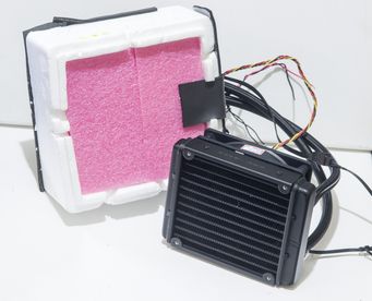
Previous design from 2018-2020 years successfully used for various LTZ1000A voltage reference and small resistance (such as Fluke 742A) standards temperature tests. It was using 40W single-stage TEC element, closed-loop watercooling pump+HX and copper heatsink as thermal exchanger.


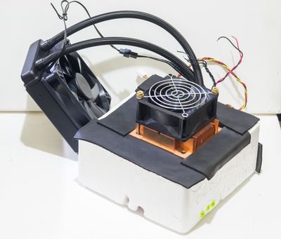
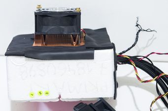
80 mm fan installed on thermal chamber to actively mix air within insulated chamber. This helped to obtain uniformity better than 0.2 °C when passive or <5W active devices are used in chamber as DUT.

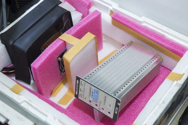
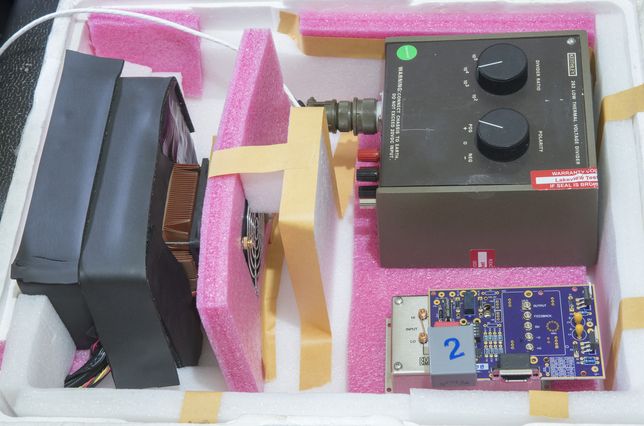
Components layout in the larger Styrofoam box for better thermal ambient insulation shown on photos below.


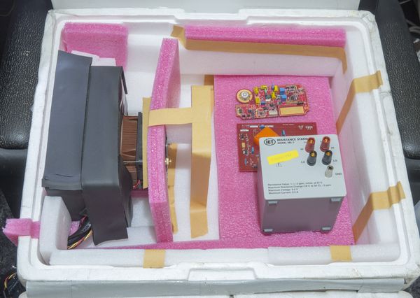
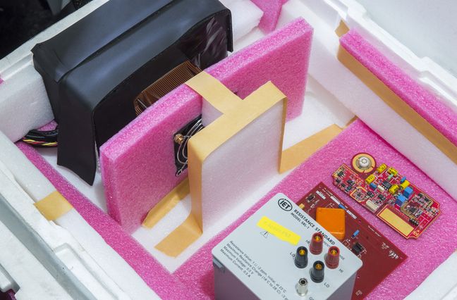
Device under test examples, such as Wavetek 7000 DC voltage reference and Keithley 262 + EM A10 nanovolt amplifier were tested using this chamber.


This chamber also tested with Arroyo TECPak 585 to perform multiple hour sweep with slow temperature ramp. Temperature and data acquisition was controlled by xDevs.com's teckit open-source application.


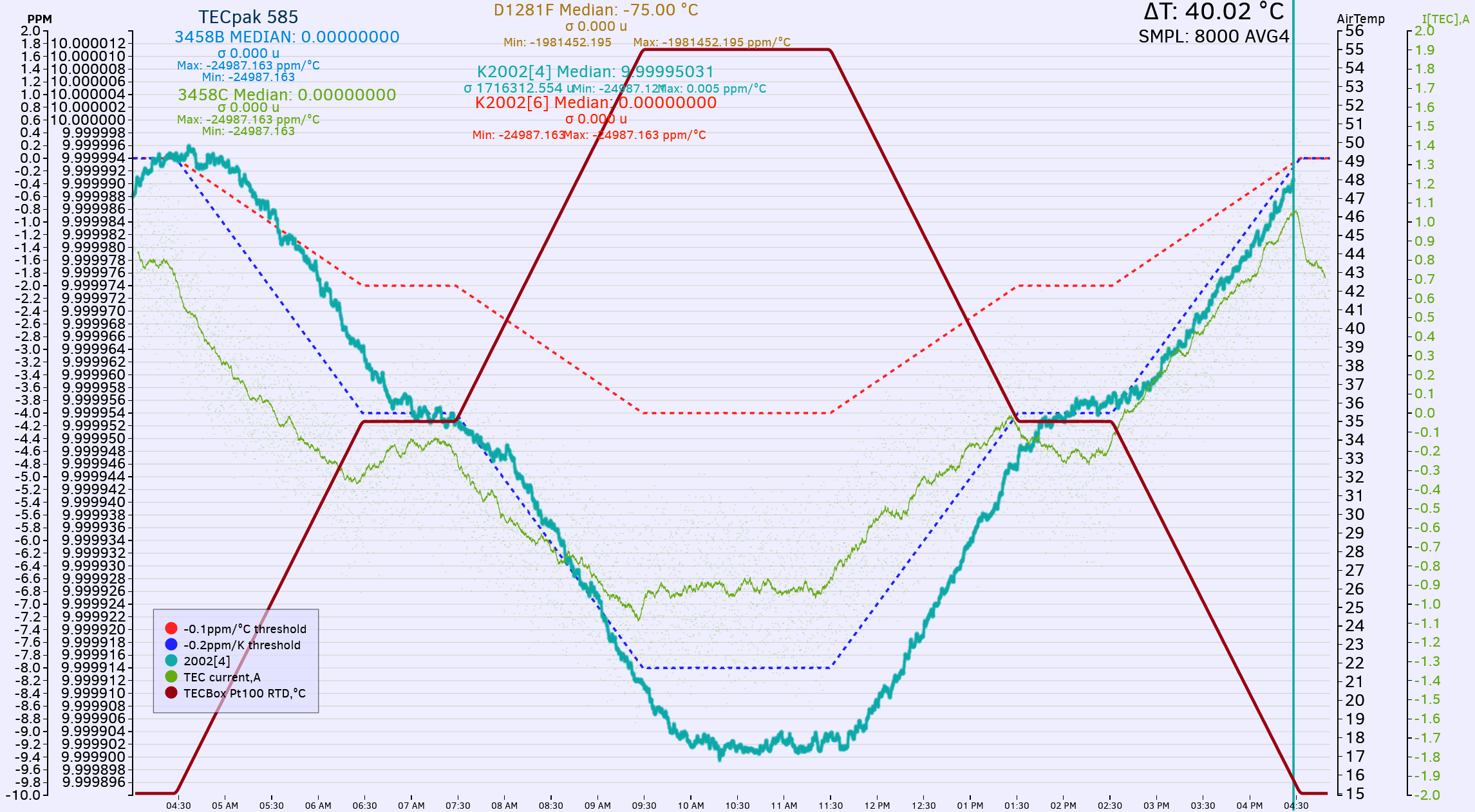
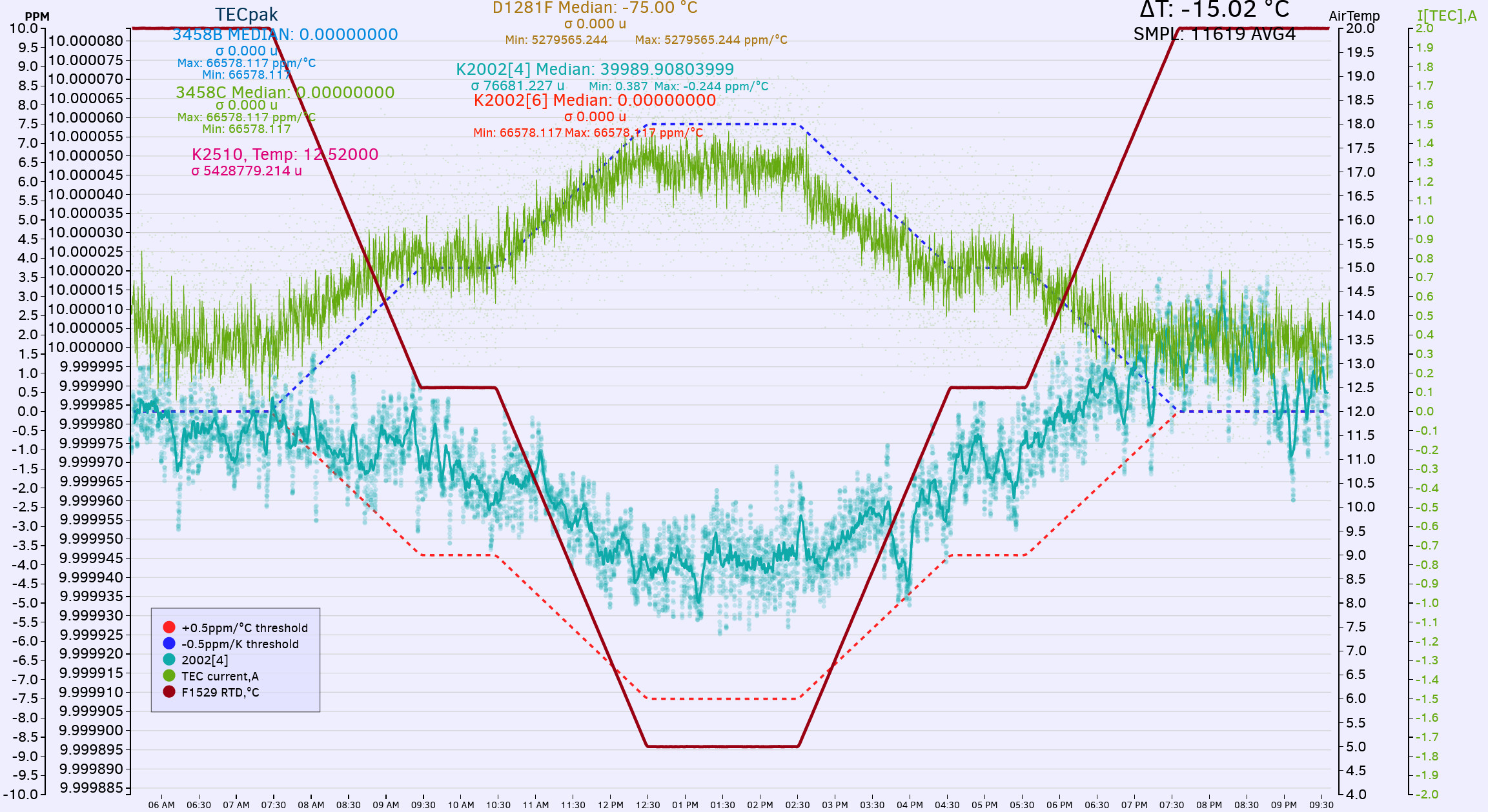
First plot shows controlled temperature ramp from +15.0 °C to +55 °C with intermediate soak time at half-scale, +35 °C. Changing temperature by 40 °C allow us to evaluate temperature coefficient (stability) of IanJ's PDVS2 mini with good resolution and confidence. In this case voltage dropped from 9.999994 VDC to 9.999902 VDC.

Overall time for this ramp was 12 hours, with ramp speeds 0.125 °C/minute. Now lets zoom in and look into middle step flat section:


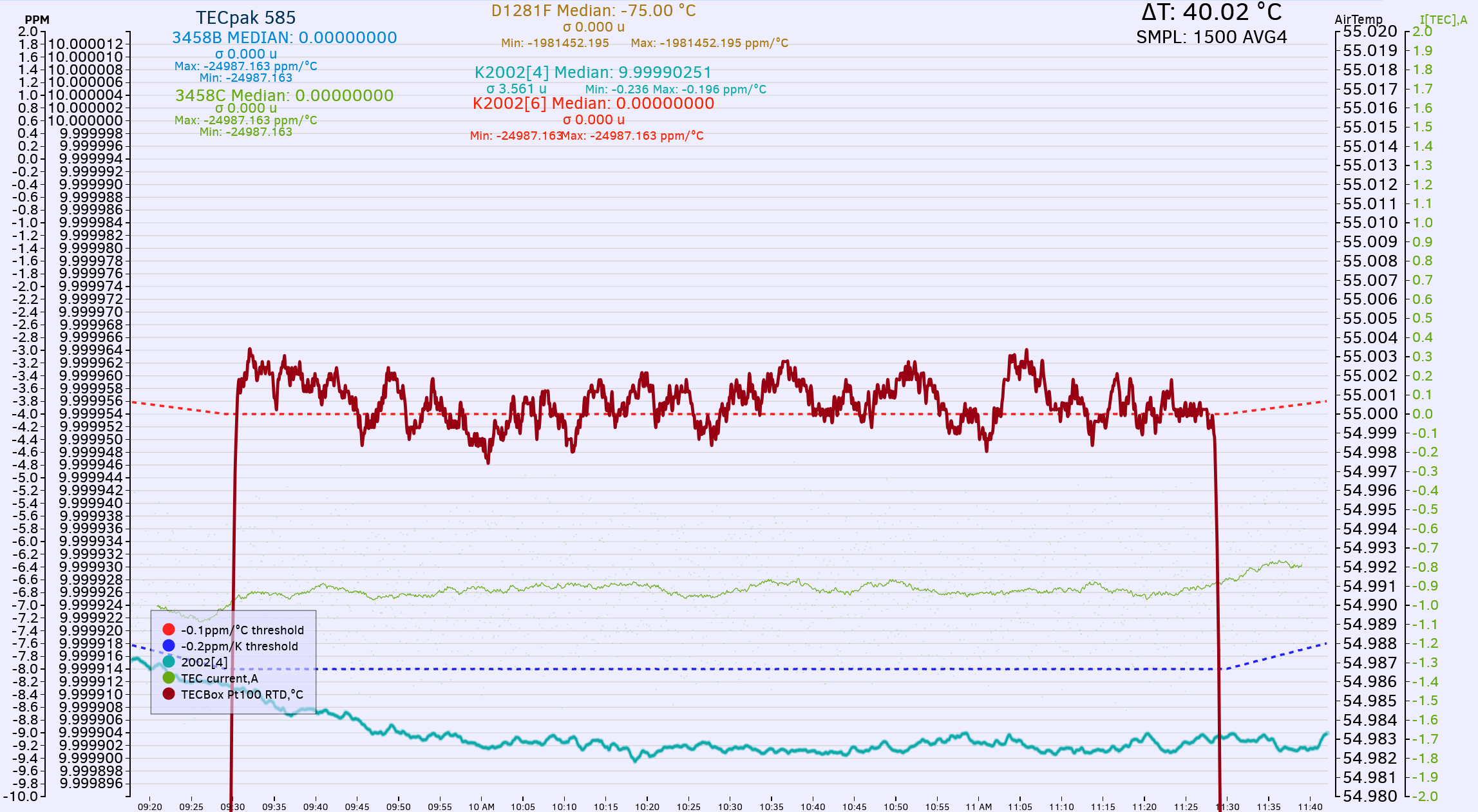
Temperature axis rescaled to much finer resolution here, at 0.001 °C per division. Arroyo TECPak provided nice and stable control, with variations of temperature readout less than +/- 0.003 °C during step time 1 hour.

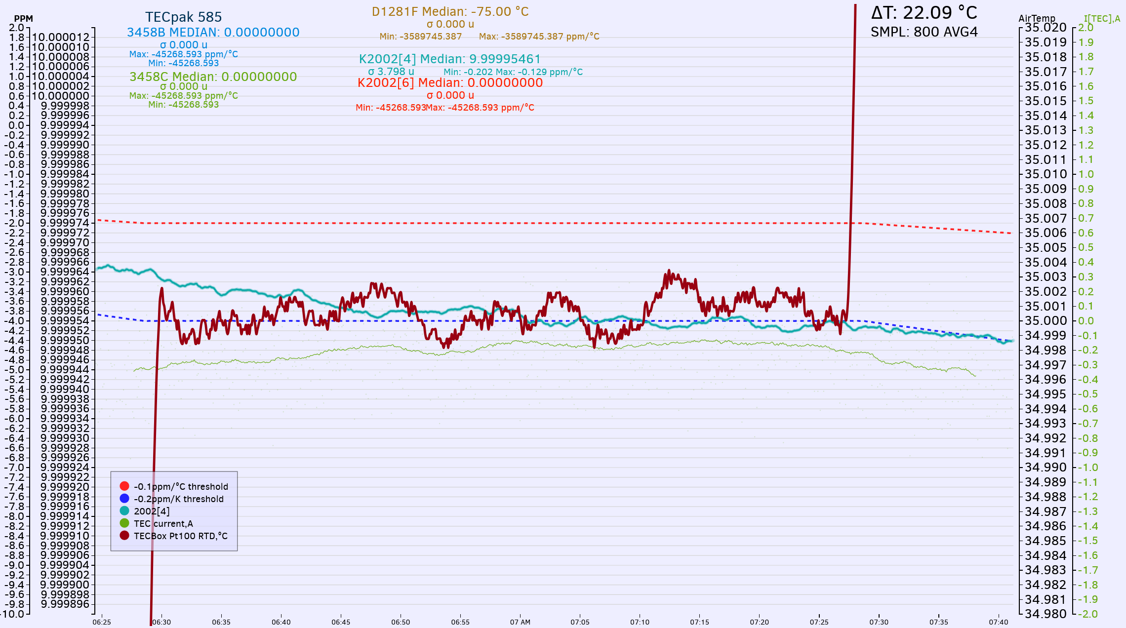
Next plot shows 2 hour step at peak +55 °C temperature. Again, no problems or overshoots, while maintaining +/-0.004 °C temperature stability.


Opposite test with going sub-ambient temperatures, with ramp from +20 °C to +5 °C during 15 hour test.


New MEGA TEC chamber, revision 2021

But I always wanted to have ability of testing larger devices, such as full size 19" DMM (Keysight 3458A, Fluke 8508A and alike). Ideally chamber should also support even bigger and heavier devices, such as multi-function calibrator Fluke 5720A or Datron 4808.

However testing such active instruments is not practical or possible with low power 40W Peltier TEC. This is problem for next monster chamber project aimed to solve.

After checking available space on bench and targeted use cases next feature set was established as target:

* Big enough to fit 5720A+5725A and 3458A or multiple 732A
* 850 x 600 x 500 mm inner volume
* High power TEC module assembly to allow fast control, to support max 900W active load inside chamber
* Desired temperature range from 0 °C to +60 °C
* Temperature uniformity better than 0.1 °C
* Temperature stability better than 0.05 °C with heat load <50 W
* Temperature stability better than 0.1 °C with heat load 500 W
* Watercooling loop for TECs to allow uniform 50-100mm isolation from ambient
* Ambient influence less than 0.01 °C/°C
* Possibility for humidity control?
* Possibility for pressure control?
* Easy removable front door\lid to allow DUT management
* Material BOM cost less than $500 USD

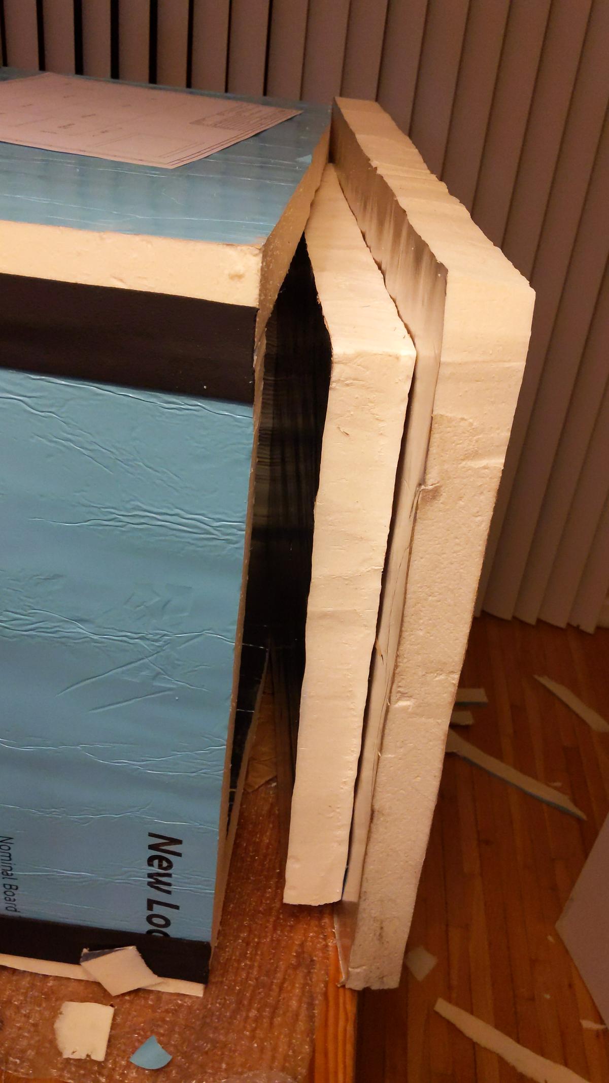
Dow Super TUFF-R R-13 foam faced board was used as a starting point to provide robust thermal insulation. Two sheets were acquired from local
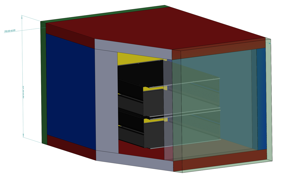
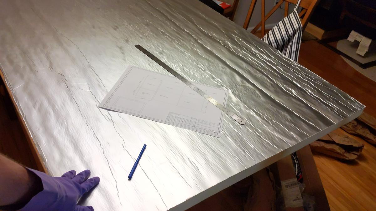
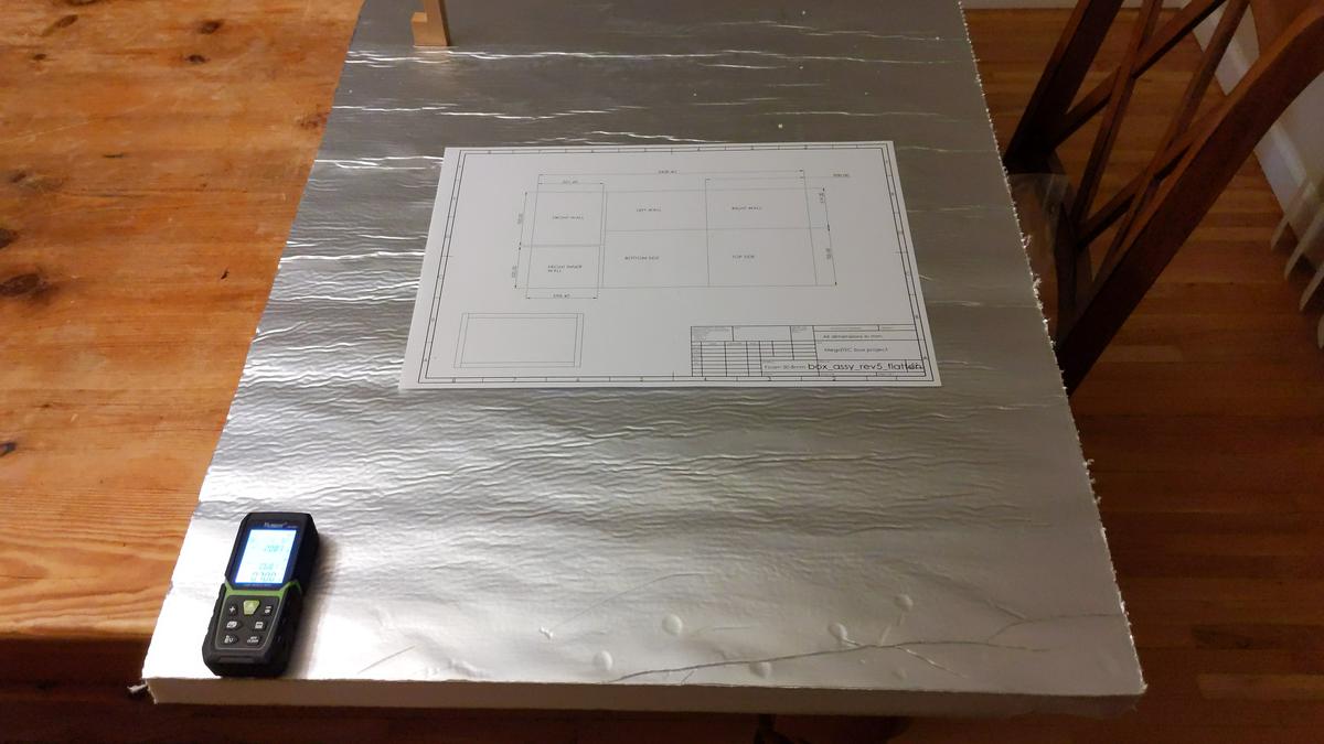
 Home Depot store

Simple CAD was sketched together with dimensions in mind to fit all parts on a 1.25 sheets.


How let's cut board to pieces and start layout


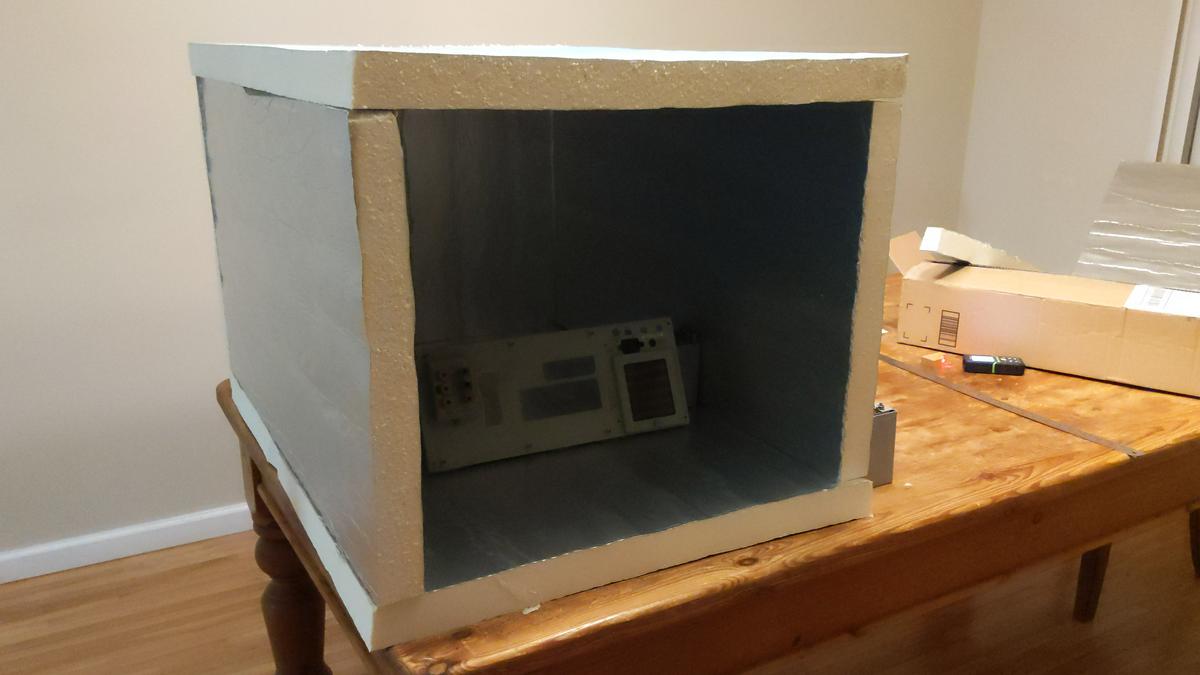
We can use random 8½-digit DMM (Advantest R6581T) to demonstrate available room in chamber.


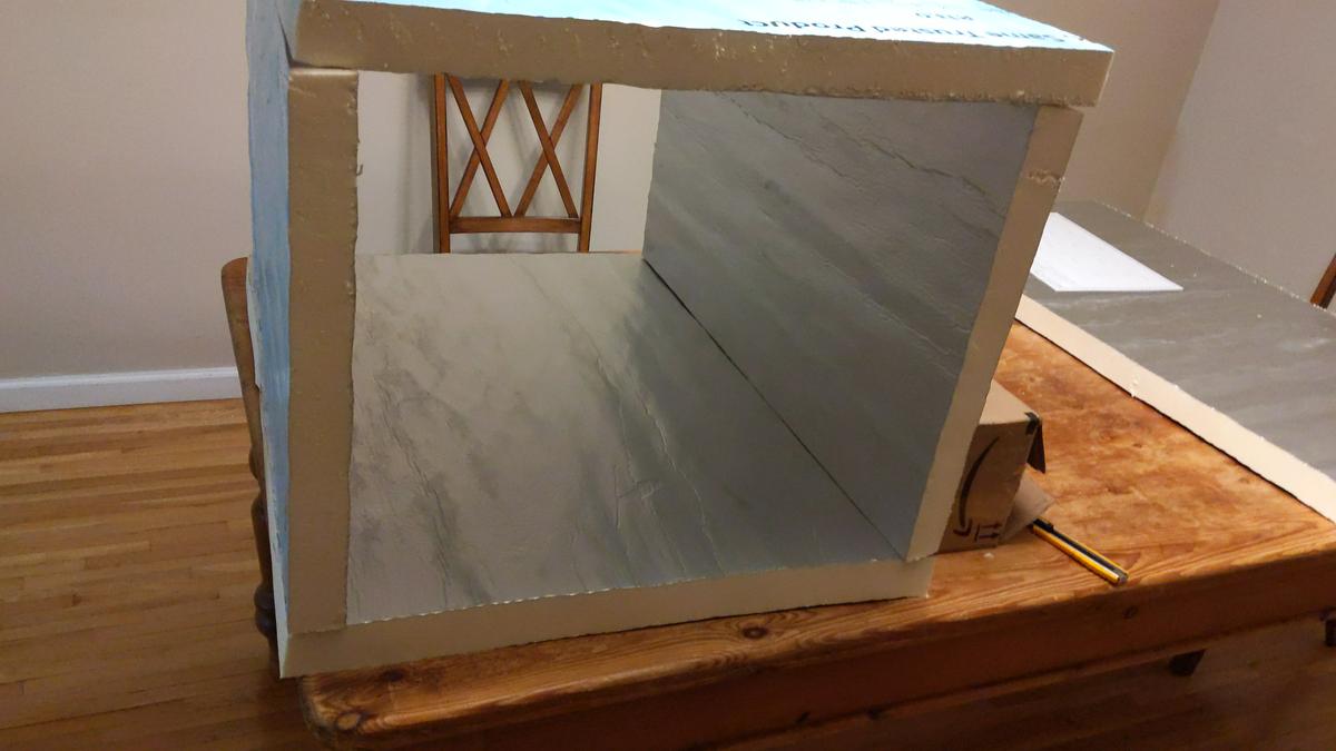
Even bigger devices, such as ESI 242D resistance system could fit in chamber. Sideways only  :-DD

However main goal to fit 5720A+5725A+3458A is met.


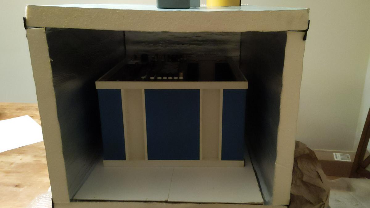
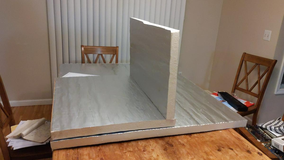
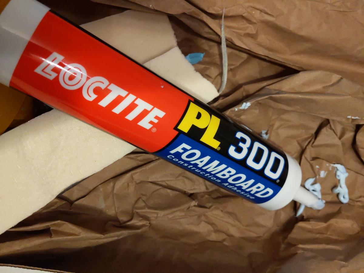
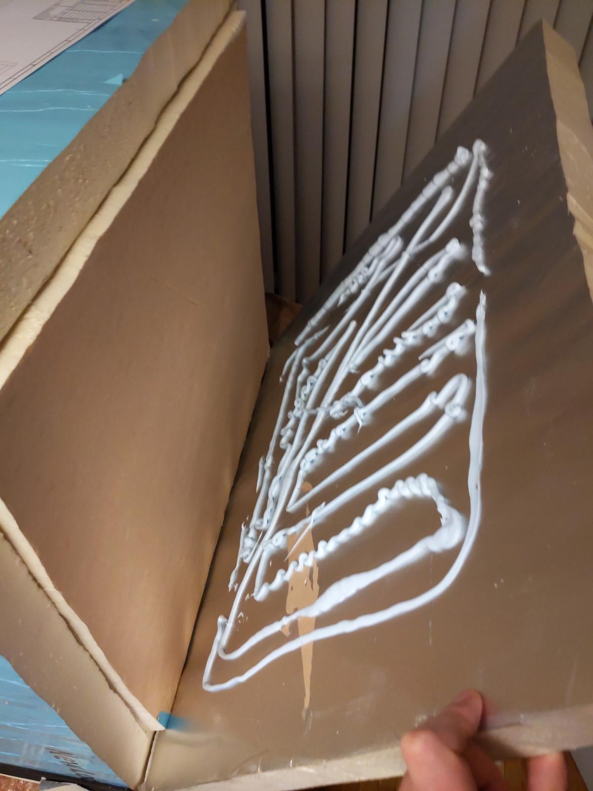
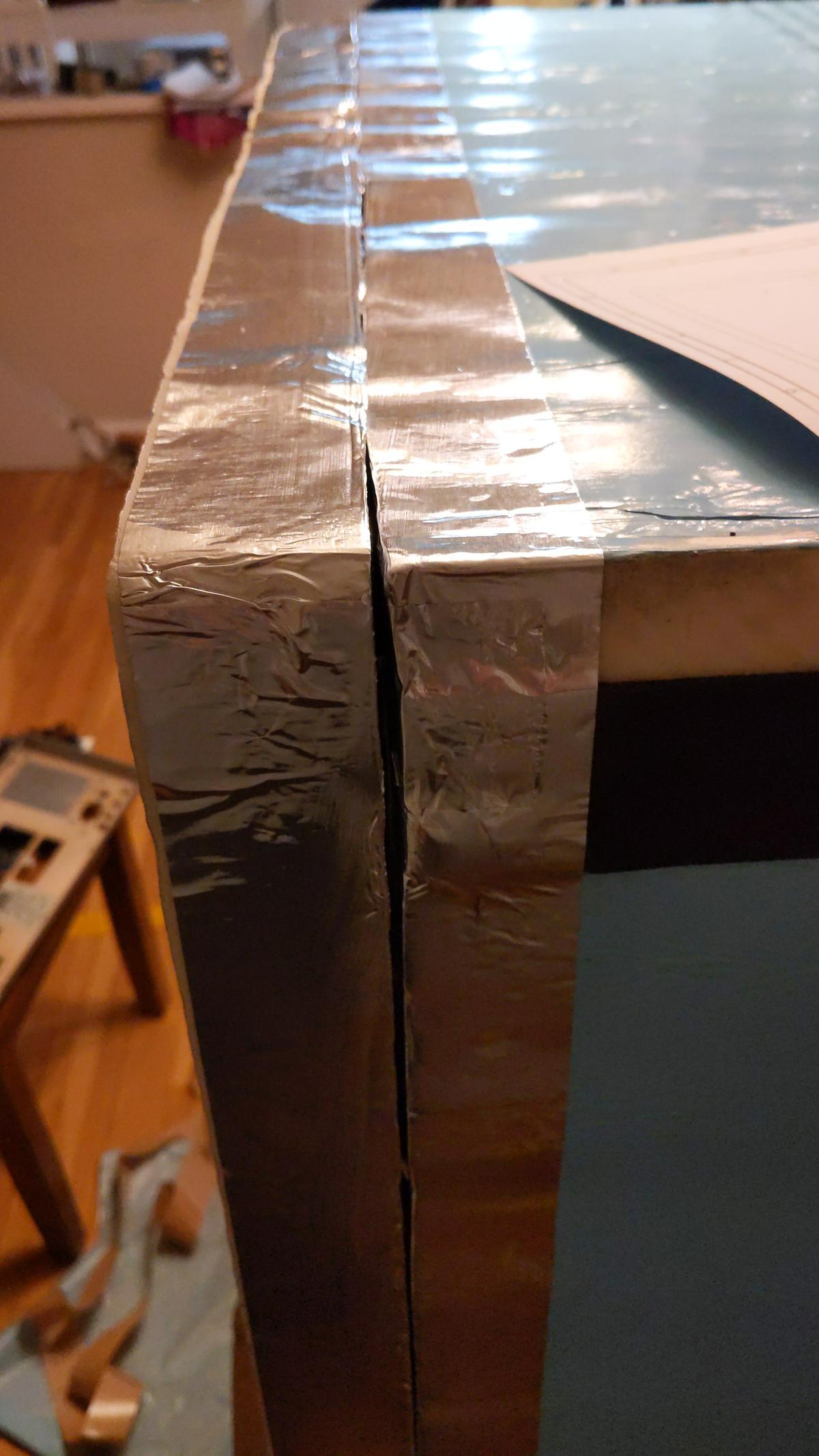
Looking pretty good, time to glue the edges on all walls and attach them to base sheet. Special Loctite PL300 latex-based foam-board glue was used to ensure good adhesion to foam wall. Full curing time of this glue is 7 days.

It is designed to be operated in temperature range from -17.7 to +77 °C. This is good enough for our design target.


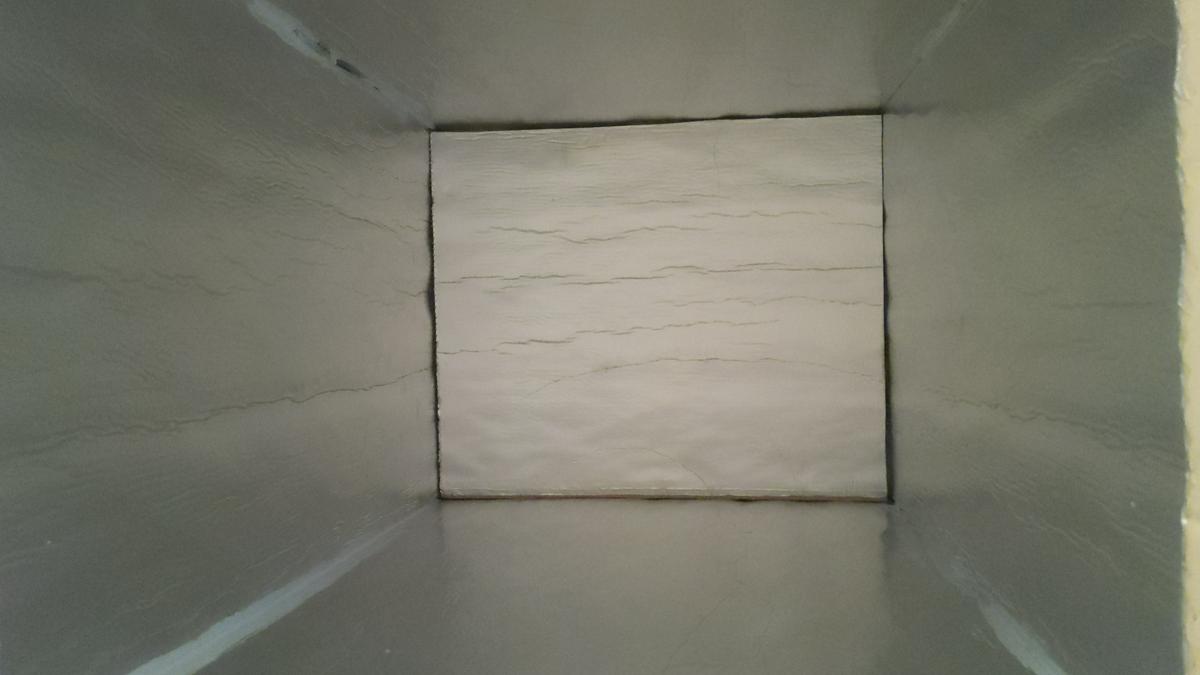
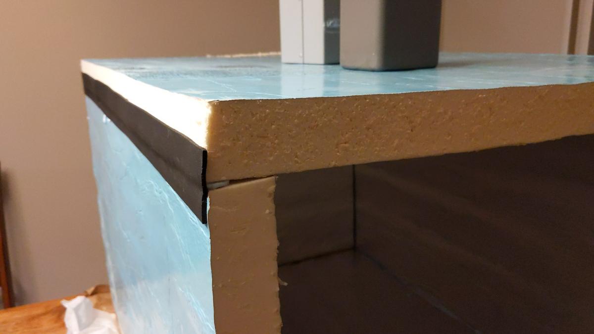
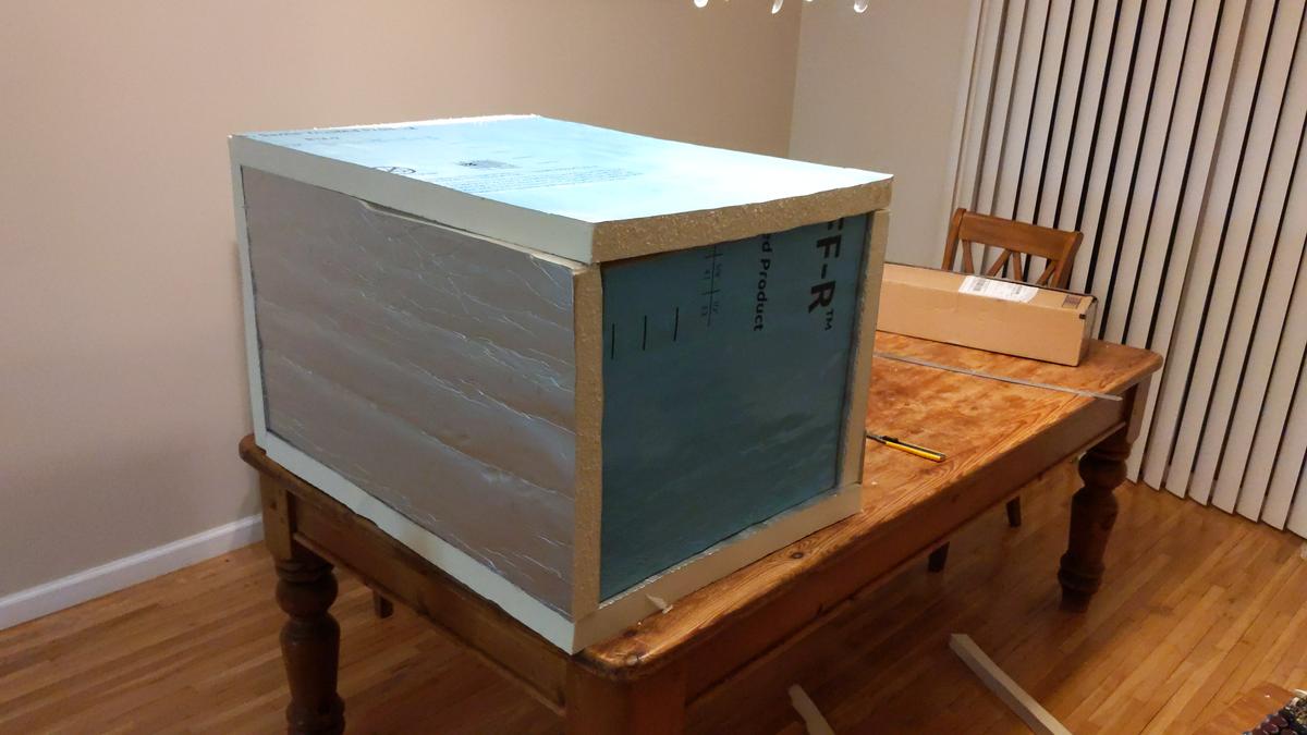
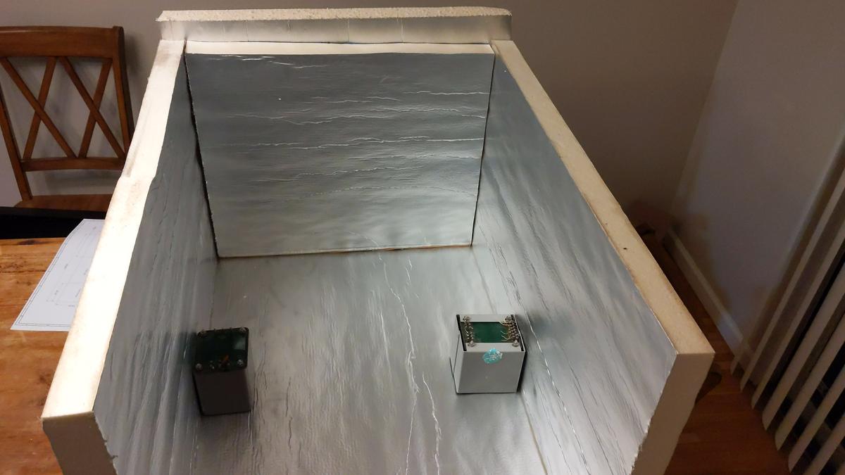
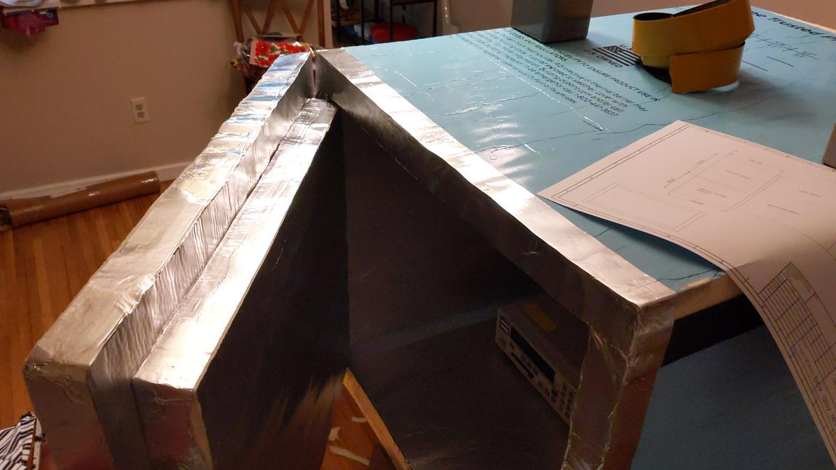
Foam is relatively easy to deform, so to improve reliability and better practical use edges faced with aluminum thin foil. In final use there will be also sealing gasket around the front and rear lids to ensure air-tight seal during chamber operation.


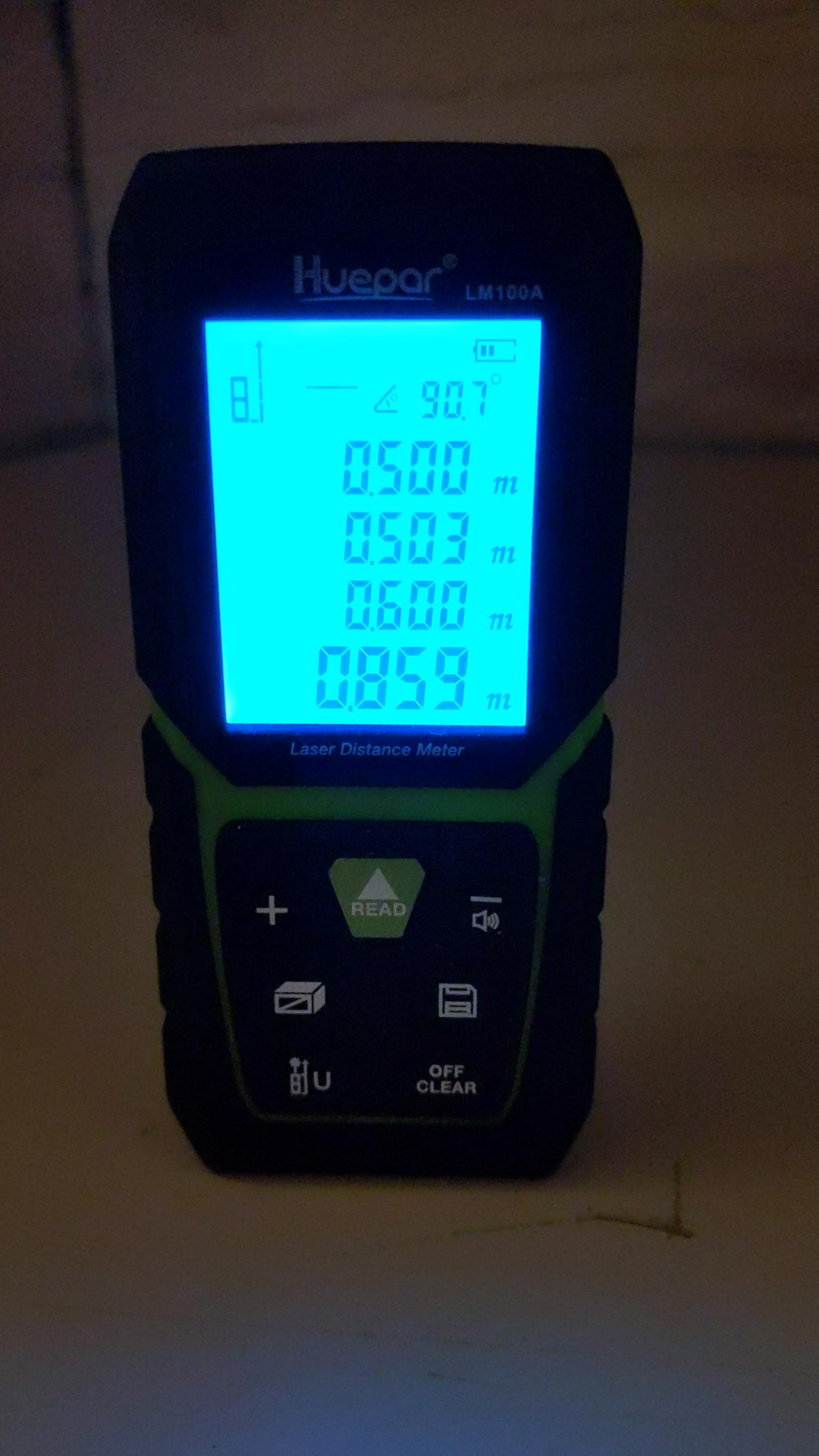
Inner dimension requirements are also met:


<h3>First test</h3>

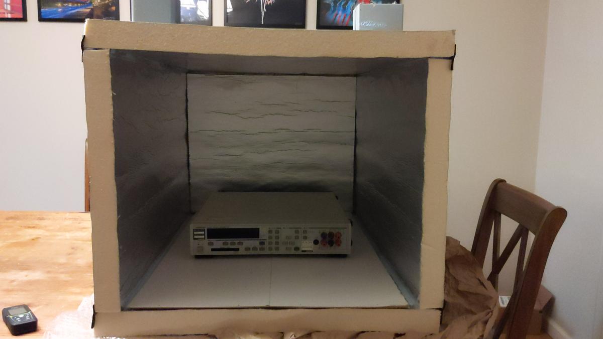
As chamber is curing, I've put old electronics and decided to run a 132 hour sweep from +38°C to +5°C and back with help of only 40W TEC module. This will give initial idea if such large chamber concept on the right track.


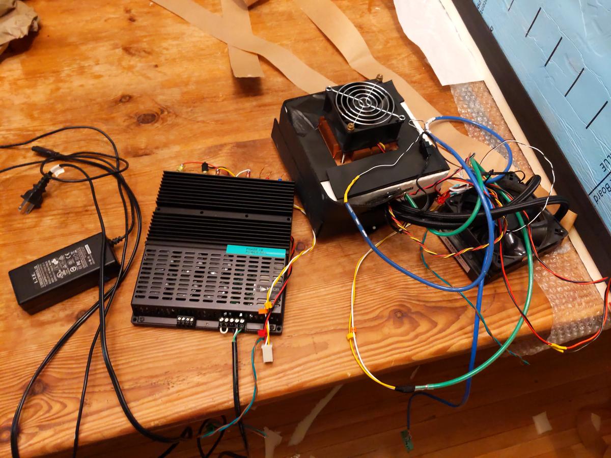
Vicor AC-DC supply provides +12V for watercooling pump/radiator fan and +6V for inner chamber mixing air fan.


Good old 
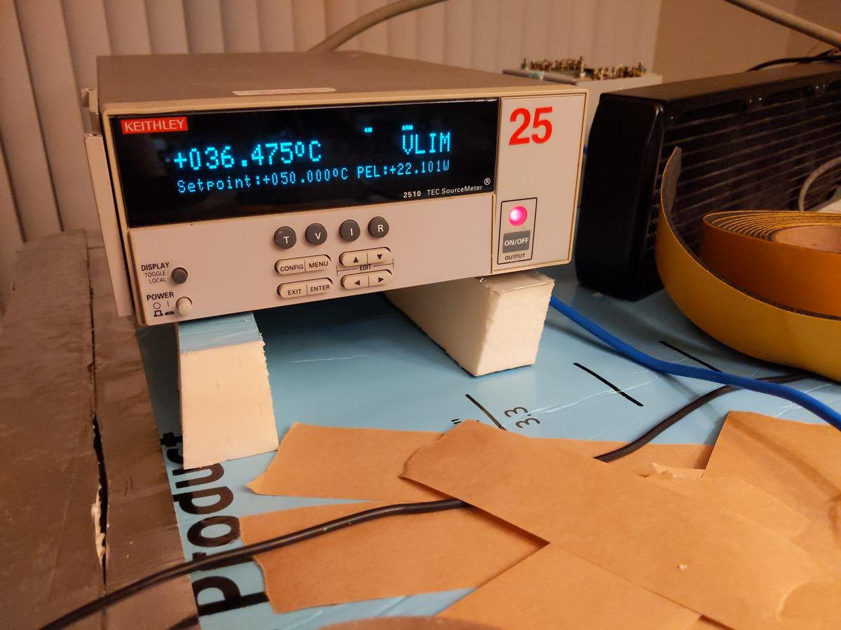
Keithley 2510 TEC SMU was used as temperature PID-controller.


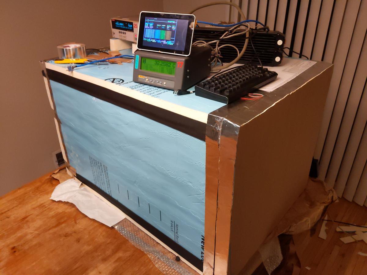
Additional measurement was also taken with calibrated 
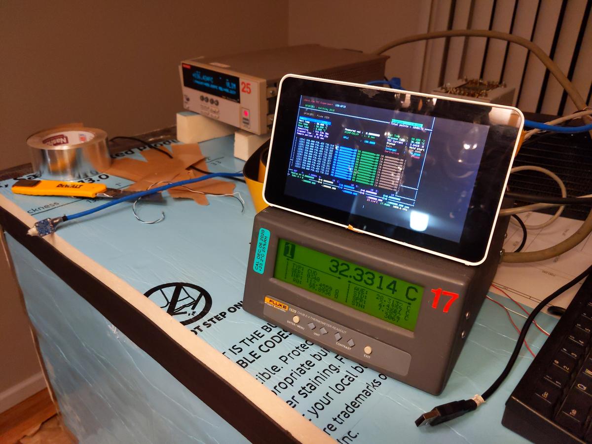
Fluke 1529 Chub-E4 + Omega RTDCAP PT100 sensor.


Raspberry Pi 3 used to run teckit application and store measurement results into DSV-file.

To be continued...
« Last Edit: February 21, 2021, 07:11:57 am by TiN »
YouTube | Metrology IRC Chat room | Let's share T&M documentation? Upload! No upload limits for firmwares, photos, files.
 

Offline Vgkid

  • Super Contributor
  • ***
  • Posts: 2710
  • Country: us
Re: DIY Large thermal chamber for metrology T&M testing
« Reply #1 on: February 21, 2021, 09:12:42 am »
I look forward to seeing this build.
If you own any North Hills Electronics gear, message me. L&N Fan
 

Offline nfmax

  • Super Contributor
  • ***
  • Posts: 1559
  • Country: gb
Re: DIY Large thermal chamber for metrology T&M testing
« Reply #2 on: February 21, 2021, 09:18:07 am »
If you are using large equipment in such a chamber, you should support it on a grid or wire shelf off the base, so the internal fan can circulate air over all surfaces, including the equipment bottom panel.
 
The following users thanked this post: TiN

Online Kleinstein

  • Super Contributor
  • ***
  • Posts: 14168
  • Country: de
Re: DIY Large thermal chamber for metrology T&M testing
« Reply #3 on: February 21, 2021, 10:10:54 am »
For the base I would consider a aluminium plate. This helps to get a uniform temperature also under the instrument and it could help to mount supply cables (likely some 110 V outlets). Heat transfer via cables could than first go to the relatively large plate.

High powert thermoelectric cooling comes at the price of quite some thermal path to the outside, even of the full power is not needed. The thermal conductivity of the TEC elements is relatively high. Less powerful cooling would allow for better isolation. 

One could consider a modular form so that one could reduce the number of TEC elements depending on the power requitements. Another option may be to use a kind of 2 stage operation for the rare cases were one needs low temperature at relatively high power  - up to the point of using ice cubes to cool the outside of the TECs in this case. This way one could use less TEC elements, which would help normal use with lower power.

If more power is needed for heating, just additional pure heaters may be easier than additional TECs. So the TEC part would mainly need to be designed for cooling - heating would likely be sufficient anyway and if no it is easy to add extra heaters. 
 

Offline TiNTopic starter

  • Super Contributor
  • ***
  • Posts: 4543
  • Country: ua
    • xDevs.com
Re: DIY Large thermal chamber for metrology T&M testing
« Reply #4 on: February 21, 2021, 04:10:23 pm »
Quote
High powert thermoelectric cooling comes at the price of quite some thermal path to the outside, even of the full power is not needed

Can you explain a bit more? Only heat interface between outer world and inner volume are wires and two silicon pipes with coolant for TEC HX. TEC module will be mounted on the rear lid which is 101.6 mm thick (two layers of foam board).

All tubing inside and TEC "hot side" will be insulated in armaflex foam as well.
YouTube | Metrology IRC Chat room | Let's share T&M documentation? Upload! No upload limits for firmwares, photos, files.
 

Online Kleinstein

  • Super Contributor
  • ***
  • Posts: 14168
  • Country: de
Re: DIY Large thermal chamber for metrology T&M testing
« Reply #5 on: February 21, 2021, 05:27:53 pm »
The TEC module itself has thermal conduction between the sides. In the usual model for a TEC there is this thermal conduction, the peltier effect proportional to the current and the resistive loss given by resistance times current squared. The internal thermal conduction is what limits the maximum temperature difference. So one can quite easy calculate the internal thermal conduduction as maximum power (at zero temperature difference) divided by maximum temperature difference.  With a typical max. temperature difference of a little below 50 K and some 500 W of intendent max power this would be some 10 W/K, which is a pretty strong thermal coupling.
 

Offline TiNTopic starter

  • Super Contributor
  • ***
  • Posts: 4543
  • Country: ua
    • xDevs.com
Re: DIY Large thermal chamber for metrology T&M testing
« Reply #6 on: February 21, 2021, 06:10:57 pm »
Yes, but wouldn't it be compensated by temperature regulation loop?
So whatever heat/cold lost due to transfer between sides of TEC would be compensated by controller.  :-//
YouTube | Metrology IRC Chat room | Let's share T&M documentation? Upload! No upload limits for firmwares, photos, files.
 

Online Kleinstein

  • Super Contributor
  • ***
  • Posts: 14168
  • Country: de
Re: DIY Large thermal chamber for metrology T&M testing
« Reply #7 on: February 21, 2021, 06:26:03 pm »
The controller would still act against the heat loss, but the regulator has only a limited faktor to suppress external heat flow (e.g. some 0.01K/K as the target).
External disturbance can also effect the outside of the TEC and this way get a relatively fast path to the inside. With fewer TEC modules the controller would have a chance to get better suppression of external temperature variations, as it would see less disturbance in the heat flow.

One can in principle measure the temperature of the hot side and include this in the regulation. This way one could compensate much of the heat going this path in a feed forward manner instead of the regulator. This could to a large part compensate the extra heat path. However not many ready made conterlers include this function - it would not be a big deal with a DIY controller.

Less TEC elements would also save on the costs.
 

Offline Vtile

  • Super Contributor
  • ***
  • Posts: 1144
  • Country: fi
  • Ingineer
Re: DIY Large thermal chamber for metrology T&M testing
« Reply #8 on: February 21, 2021, 07:20:39 pm »
Pssst. 200 L box freezer....
 
The following users thanked this post: SilverSolder, DC1MC

Offline TiNTopic starter

  • Super Contributor
  • ***
  • Posts: 4543
  • Country: ua
    • xDevs.com
Re: DIY Large thermal chamber for metrology T&M testing
« Reply #9 on: February 21, 2021, 07:22:35 pm »
Outside of the TEC? Whole TEC assembly with cooling waterblock are inside of the chamber.

Either way, here's first plot, still using 40W watercooled TEC from old setup.


While result is mediocre versus desired spec, it is actually better than I have expected.
Distance between remote RTD sensor and control RTD is about 50cm inside chamber.

Major drawback of large volume is slooow response, so that will be investigated in future once I get more powerful TEC setup and angry fans to mix air faster.

Also visible how ambient air temperature variation due to central heating cycles about 1°C cause control temperature inside chamber change ~0.1°C. So we need better insulation :)
« Last Edit: February 21, 2021, 07:38:15 pm by TiN »
YouTube | Metrology IRC Chat room | Let's share T&M documentation? Upload! No upload limits for firmwares, photos, files.
 

Offline Anders Petersson

  • Regular Contributor
  • *
  • Posts: 122
  • Country: se
Re: DIY Large thermal chamber for metrology T&M testing
« Reply #10 on: February 21, 2021, 07:42:31 pm »
Very interesting project.
I'd like to know more how you decide on how many TECs and which models to use, and how you plan to distribute the heating/cooling effect evenly throughout such a large volume.

My own attempt uses a complex design with an inner and an outer chamber for max temperature uniformity. I've only done initial testing yet, with mixed results.
 
The following users thanked this post: lowimpedance, TiN, Kean

Offline nfmax

  • Super Contributor
  • ***
  • Posts: 1559
  • Country: gb
Re: DIY Large thermal chamber for metrology T&M testing
« Reply #11 on: February 21, 2021, 07:46:02 pm »
A useful reference for this sort of thing is the 'missing' chapter 20 on thermal control, from Philip Hobbs's book:

ftp://ftp.wiley.com/public/sci_tech_med/electro-optical/thermal.pdf
 

Offline TiNTopic starter

  • Super Contributor
  • ***
  • Posts: 4543
  • Country: ua
    • xDevs.com
Re: DIY Large thermal chamber for metrology T&M testing
« Reply #12 on: February 21, 2021, 07:53:09 pm »
Anders Petersson
If you can share your results, perhaps would be interesting to relate. In smaller volumes it is much easier to obtain uniformity, than large ones, especially with active heat sources inside.
So far I plan to use row of high speed fans that can cycle all inner air volume within few seconds.

I've bought 3xTEC cheap module to experiment:


This is next step :)
« Last Edit: February 21, 2021, 07:57:42 pm by TiN »
YouTube | Metrology IRC Chat room | Let's share T&M documentation? Upload! No upload limits for firmwares, photos, files.
 

Online Kleinstein

  • Super Contributor
  • ***
  • Posts: 14168
  • Country: de
Re: DIY Large thermal chamber for metrology T&M testing
« Reply #13 on: February 21, 2021, 07:59:53 pm »
This looks like an interesting design - a bit like a wind tunel.

To decide one the number of TECs needed, the cooling part should be relevant (extra heating is easy and could use simple resistors instead of TECs). Based on DUT power and heat losses / isolation one can estmate the required power and required number of TECs.  At 1/2 the maximum temperature difference one may get something like 1/4 to nominal power. So don't get fooled by the nominal power rating - this is for zero difference. For best efficiency the current would be reduced and thus an even smaller power. This may not be econimic, but I would still plan with some 20% below nominal current, as heat sink qualitiy is less than perfect and the last bit of current mainly helps at high temperaure difference.

This also shows that cooling the ouside (especially for peak power needs) or at least a very efficient heat sink really helps. Reduce the temperature difference from some 25 K to 5 K would allow something like 4 times the cooling power per element or getting away with 1/4 the elements.
 

Offline Anders Petersson

  • Regular Contributor
  • *
  • Posts: 122
  • Country: se
Re: DIY Large thermal chamber for metrology T&M testing
« Reply #14 on: February 21, 2021, 08:22:44 pm »
TiN, so far I only tested the lowest temperature I could reach with 500W spread over 12 TECs and I was disappointed. I'll share in a separate thread when I have more results.

In my case, I suspect that the fan motor adds significant heating to the chamber. That might not be a problem in your scenario, but do include the fans in your heat flows budget calculation. The design pictured uses a single 180mm fan with the reasoning that a large fan is more efficient than small ones. But the narrow air channels of the design (see attachment) probably restricts the flow since I see poor air flow with anything less than full fan speed. I think this is due to the low static pressure rating of this type of fan.
I'm now looking into driving the fan with a motor outside the chamber, via a custom shaft. The problem has been aligning the moving parts with enough precision to avoid lots of vibration.
 

Offline Anders Petersson

  • Regular Contributor
  • *
  • Posts: 122
  • Country: se
Re: DIY Large thermal chamber for metrology T&M testing
« Reply #15 on: February 21, 2021, 08:30:24 pm »
TiN, your 3x TEC module looks fit for the purpose, though I'm not sure you can cool as cold as you want. (Unless you do as I and use ice water as coolant.)

What I'm doing is to connect the water blocks in parallel instead of in series, using T connections to a wider tube. The idea is to restrict the flow less and avoid cooling the next water block with water heated from the previous one. I don't know yet what difference this makes -- I will measure water temperature to learn more.
 

Offline TiNTopic starter

  • Super Contributor
  • ***
  • Posts: 4543
  • Country: ua
    • xDevs.com
Re: DIY Large thermal chamber for metrology T&M testing
« Reply #16 on: February 21, 2021, 08:32:49 pm »
I'd expect thermal gradients on your metal plates are much bigger issue than a fan airflow.
Usual approach is to maximize surface area for heat exchangers, so there is more air in contact with cold surfaces.

In this project I don't do much science and math to calculate all details, it's more hands-on "let's build something and see how bad it is" instead of careful modelling of heatflow and physics. After all this is all hobby project, not a business application.
YouTube | Metrology IRC Chat room | Let's share T&M documentation? Upload! No upload limits for firmwares, photos, files.
 

Offline jbb

  • Super Contributor
  • ***
  • Posts: 1135
  • Country: nz
Re: DIY Large thermal chamber for metrology T&M testing
« Reply #17 on: February 21, 2021, 11:39:34 pm »
You know, if someone’s feeling particularly cunning it is possible to make heat pipes without internal wicks, which will only conduct heat up. That can make a thermal diode, so theoretically half the Peltier elements could sit on the ‘cathode’ of a thermal diode and only provide cooling as required.

(Note, water is often used as a working fluid in the heat pipes so temperature needs to remain above 0 deg C.)
 

Offline TiNTopic starter

  • Super Contributor
  • ***
  • Posts: 4543
  • Country: ua
    • xDevs.com
Re: DIY Large thermal chamber for metrology T&M testing
« Reply #18 on: February 22, 2021, 03:12:45 am »
Sounds complicated... I do not have access to metal working shop / machining / lathe etc to mess with stuff like heatpipes.

Received Edwards E2M8 vacuum pump for future pressure chamber experiments. I expected it to be somewhat smaller, but its quite a hefty 24 kg monster.
Gotta learn a bit about vacuum gear and buy more accessory like oil mist filter, KF25 flange adapters, pressure valve ports, solenoid valves, etc.. But that's a story for another time, not a current priority for thermal chamber work.

YouTube | Metrology IRC Chat room | Let's share T&M documentation? Upload! No upload limits for firmwares, photos, files.
 

Offline jbb

  • Super Contributor
  • ***
  • Posts: 1135
  • Country: nz
Re: DIY Large thermal chamber for metrology T&M testing
« Reply #19 on: February 22, 2021, 05:48:43 am »
Sounds complicated...

Received Edwards E2M8 vacuum pump ... buy more accessory like oil mist filter, KF25 flange adapters, pressure valve ports, solenoid valves, etc...

:D
 

Online Kean

  • Supporter
  • ****
  • Posts: 2089
  • Country: au
  • Embedded systems & IT consultant
    • Kean Electronics
Re: DIY Large thermal chamber for metrology T&M testing
« Reply #20 on: February 22, 2021, 07:01:30 am »
Also visible how ambient air temperature variation due to central heating cycles about 1°C cause control temperature inside chamber change ~0.1°C. So we need better insulation :)

In an earlier post you showed a photo of your chamber door with metal tape connecting the outside air to the inside...  :-//
 

Online Kleinstein

  • Super Contributor
  • ***
  • Posts: 14168
  • Country: de
Re: DIY Large thermal chamber for metrology T&M testing
« Reply #21 on: February 22, 2021, 08:15:21 am »
One may not need better insulation. With TEC elements the main heat path from outside to inside is likely through the TECs anyway.

Better tuned PID parameter (especially more gain - an initial test usually uses a reduced gain to avoid oscillation) can do a lot. For the heat through the TECs feed forward compensation can do a lot - something like a factor of 5 to  100 compensation. How good this works depends on controller (e.g. if it includes linearization and provisions for the 2 nd sensor and feed forward at all).


The following users thanked this post: Kean

Offline Anders Petersson

  • Regular Contributor
  • *
  • Posts: 122
  • Country: se
Re: DIY Large thermal chamber for metrology T&M testing
« Reply #22 on: February 22, 2021, 01:26:41 pm »
Kleinstein has a point with the heat path through the TECs, but assuming the TECs are operating, their heat loss is already included in the efficiency number, no?

Trying to calculate the influence of the large box that TiN has:

Outer surface of box with inner volume 850 x 600 x 500 mm and wall thickness 50 mm = 2 * (900*650 + 900*550 + 650*550) mm2 = 2.875 m2

I'm not sure how to convert the R-13 rating of the "Super TUFF-R" material to W/mK (watt per meter kelvin) but Google says that styrofoam is 0.033 W/mK.

Plugging in these values in https://www.engineeringtoolbox.com/conductive-heat-transfer-d_428.html and assuming a 20 K temperature difference ("delta-T"), I calculate a heat loss of 37.9 W. This is a simplified number that doesn't account for the shape of the box or additional leakage along joints and cables.

This number is very small compared to the goal to "support max 900W active load inside chamber" but I doubt that's a realistic goal it you wish to achieve a large delta-T:

At 20 K delta-T, the heat pumping capacity (Qc) of a common TEC1-12706 is 35W at 4.5A. (https://peltiermodules.com/peltier.datasheet/TEC1-12706.pdf)
For TEC1-12715, the capacity is 100W, but this takes 13A. (https://peltiermodules.com/peltier.datasheet/TEC1-12715.pdf)

You will then need one TEC1-12706 at its max effective power to maintain a 20 K delta-T in the chamber without any heat-generating DUT.

While the box heat loss is linear with delta-T to the room, the TEC delta-T is in relation to the coolant water, so this also assumes the radiator is 100% efficient in cooling the water. A single TEC1-12706 should consume about 52 W, so the radiator needs to dissipate 52+35 W ~= 90 W in this case.

A DUT that generates the same amount of heat, 35 W, would require a second TEC that adds another 90 W to be dissipated by the radiator. I would love to see some W/mK numbers for computer radiators! Then we can calculate the coolant temperature.

This is only my understanding of the physics involved, please correct me!

PS. I'm focused on cooling the chamber. Heating is easier, as Kleinstein wrote.
 

Online Kleinstein

  • Super Contributor
  • ***
  • Posts: 14168
  • Country: de
Re: DIY Large thermal chamber for metrology T&M testing
« Reply #23 on: February 22, 2021, 02:05:46 pm »
The internal heat conduction is part of the efficiency number in the data-sheets. It is the main effect to reduce the power with temperature effect. So one can directly get the number from the curves. For the TEC1-12706 this would be some 0.8 W/K for a single element. So 2 or 3 such elments would be a heat path about as strong as the rest of the box.

A point usually not included in the datasheets is the thermal contract. Here data-sheet usually assume perfect contact and thus unrealistic numbers.  Having additional thermal resistance increses the actual temperature difference over the TEC when cooling. This leads to a reduced current for best cooling a little. Unless one really needs the full temperature difference it is anyway better to reduce the current a little to improve the efficiency. So instead of the theoretisch maximum of some 6.4 A in the TEC1-12706 datasheet one should reduce the current a little, e.g. more like 5 A. A higher current would mainly add power loss and may even reduce the real worl cooling power.

The calculation looks OK. The resistance seems to be quite temperature dependent. This may lead to slightly lower power consumption with lower average temperature - so maybe the 52 W number maybe slightly high, but not really much. The main conclusion stays the same: the hot side sees a lot of power  - some 40% efficiency for 20 K difference sounds plausible.
With this numbers a 600 W power source inside does not sound plausible with peltier cooling alone.
 

Offline MK

  • Regular Contributor
  • *
  • Posts: 234
  • Country: gb
Re: DIY Large thermal chamber for metrology T&M testing
« Reply #24 on: February 22, 2021, 02:33:27 pm »
Dont forget to allow for the significant loss of available pumping capacity at higher delta T. Some years ago we required a cooled PMT at 5C in a potentially 50C ambient (worst case), we could only pump ~4 Watts of heat out of the insulated PMT enclosure for ~50Watts input power. it was a theoretical 60W peltier, but unless we went to water cooled cold plate we could not put in more than 50W with the largest heatsink we could fit in the case, without the heatpumping capacity going down again.
« Last Edit: February 22, 2021, 02:38:02 pm by MK »
 

Offline Vtile

  • Super Contributor
  • ***
  • Posts: 1144
  • Country: fi
  • Ingineer
Re: DIY Large thermal chamber for metrology T&M testing
« Reply #25 on: February 22, 2021, 02:41:44 pm »
HoHoHold your horses! Is that R13-value in imperial pseudo units ... Not the real units which Yankees refer sometimes as RSI-value.
 

Online dietert1

  • Super Contributor
  • ***
  • Posts: 2057
  • Country: br
    • CADT Homepage
Re: DIY Large thermal chamber for metrology T&M testing
« Reply #26 on: February 22, 2021, 09:05:25 pm »
One difficulty i found when using multiple TECs was mounting them with good thermal contact. Usually i glue them in between, but was wondering about thermal expansion/contraction during usage. Once i made the mistake to glue two TECs side by side in between one heatsink and one oven.
If you use grease, it may work for some time, but grease also has a tendency to become glue after many temperature cycles. Watch out with multiple TEC devices!

Regards, Dieter
 

Offline Anders Petersson

  • Regular Contributor
  • *
  • Posts: 122
  • Country: se
Re: DIY Large thermal chamber for metrology T&M testing
« Reply #27 on: February 22, 2021, 10:19:58 pm »
Dont forget to allow for the significant loss of available pumping capacity at higher delta T.

If you meant my calculations, I did pick the Qc from the "datasheet" based on 20 K delta-T. As you say, the theoretical pumping capacity goes to zero somewhere around delta-T of 60 K no matter the power applied.

HoHoHold your horses! Is that R13-value in imperial pseudo units ... Not the real units which Yankees refer sometimes as RSI-value.

I don't know what they mean by R13 so I picked an assumed W/mK value.

One difficulty i found when using multiple TECs was mounting them with good thermal contact.

TiN's picture of the heat sink assembly shows the water blocks are individually pressed in place by screws, and I assume the TECs are pressed at the same time. That should solve the problem of allowing expansion...?
 

Online mzzj

  • Super Contributor
  • ***
  • Posts: 1243
  • Country: fi
Re: DIY Large thermal chamber for metrology T&M testing
« Reply #28 on: February 22, 2021, 10:47:24 pm »
I highly recommend playing around with Kryotherm peltier calculator software https://kryothermtec.com/kryotherm-software.html
It allows you to "build" your cold box and cooling system.

But even without starting the calculator I can tell you right away that 900W heat load with peltiers would be madness. :horse:

To cool 900W heat load to 0 degree C would take some serious amount of hardware:  30x Frost-74 peltier modules parallel, 30x LARGE cpu heatpipe coolers on hot side and 30x smaller cpu coolers on cold side.  :-DD
"Efficiency" would be actually pretty decent thanks to several parallel modules run at lower than rated voltage. You would need only 1.3kW power supply for the peltier modules.  :popcorn:
 

Offline TiNTopic starter

  • Super Contributor
  • ***
  • Posts: 4543
  • Country: ua
    • xDevs.com
Re: DIY Large thermal chamber for metrology T&M testing
« Reply #29 on: February 23, 2021, 12:20:07 am »
Madness it is. I don't want to deal with phase-change refrigeration in this project. And watercooling loop capacity for peltier is indeed fit for 1500W.

Also 0C at 900W maybe not possible, but that's rather corner case. I'd be happy with +16C at that power load (to allow testing 18-50C range for commercial T&M gear) and use colder only for special cases (when load is much less).
Specs are not written in stone, but rather a best target to get. Temperature uniformity and stability in practical 16-40C range is most important for me here.

Anders Petersson
Calculation is fun, but I don't think it align with reality here much. Right now chamber at +17 degrees (ambient is 23.5) and K2510 reported power for TEC is 11W.
When chamber temperature was at +38 degrees (same ambient) K2510 used about 18-20W. So it is at least twice less than your calculated 38W heat loss.

Also I don't need very large temperature difference and fairly confident that coolant water could be kept around +30..35°C max. So that gives delta-T about -40°C at maximum (Tset 0C from +30 coolant temp + ThetaJ) or +30°C (Tset +60 from +30 coolant + ThetaJ). Some good TEC modules are rated for 120-150W at Delta-T 40°C, so its not completely out of the question.
YouTube | Metrology IRC Chat room | Let's share T&M documentation? Upload! No upload limits for firmwares, photos, files.
 

Offline Rerouter

  • Super Contributor
  • ***
  • Posts: 4694
  • Country: au
  • Question Everything... Except This Statement
Re: DIY Large thermal chamber for metrology T&M testing
« Reply #30 on: February 23, 2021, 01:48:44 am »
For a wide range of thermal enviroments. The way I have seen it done in the past was TEC's mounted to a refrigeration loop to make it easier to work within the delta-t requirements. As it is a cooling dominated system. Turning off the TEC-s with any signifcant heat load will make the container heat up. As for cooling. The refrigderant loop can help keep the delta t to a minimum for the highest possible heat load. While having the faster response time and precision than a compressor cycling.
 

Online Kleinstein

  • Super Contributor
  • ***
  • Posts: 14168
  • Country: de
Re: DIY Large thermal chamber for metrology T&M testing
« Reply #31 on: February 23, 2021, 08:39:08 am »
The calculated power was the thermal power to be delivered by the TEC. The power reported by the K2510  should be the electrical power going in. Especially at low temperature difference the efficiency of the TECs is not that bad, so that the thermal power can be higher than the electrical.

Modern good TEC modules seem to be at around 60-70 K maximum difference and thus halve there nominal power at 30-35 K difference. With a reduced current (because of less than perfect heat sinks) the maximum dT would be reduced somewhat. So 120 W cooling at 40 K differnece would be a really large TEC module (like 300 W nominal power).

If one needs high cooling power it would really help to lower the cooling water temperature. If it gets hard to keep it cool, it would help to reduce the current use, as this improves efficiency, at not to extreme temperature differences. Best efficiency at 40 K dT would be at about 2/3 the nominal current. With relative poor cooling of the hot side, the highest power would also be at less than the nominal current, as this would cause less heating of the hot side.


Offline TiNTopic starter

  • Super Contributor
  • ***
  • Posts: 4543
  • Country: ua
    • xDevs.com
Re: DIY Large thermal chamber for metrology T&M testing
« Reply #32 on: February 23, 2021, 09:15:56 am »
Yes, in the final heat exchanger I do plan to use large 340W TECs (most likely 6 or 8 chips), when we get there.

Here's latest chart (with just 40W TEC).


We can see it chocked up at around +13 °C point. K2510 reports 22W used now, and temperature drops a little, but I think at this point it reached the capacity.
YouTube | Metrology IRC Chat room | Let's share T&M documentation? Upload! No upload limits for firmwares, photos, files.
 

Offline Anders Petersson

  • Regular Contributor
  • *
  • Posts: 122
  • Country: se
Re: DIY Large thermal chamber for metrology T&M testing
« Reply #33 on: February 24, 2021, 02:04:05 pm »
Calculation is fun, but I don't think it align with reality here much. Right now chamber at +17 degrees (ambient is 23.5) and K2510 reported power for TEC is 11W.
When chamber temperature was at +38 degrees (same ambient) K2510 used about 18-20W. So it is at least twice less than your calculated 38W heat loss.

The power when cooling is in line with my calculation, given that the delta-T of 23.5-17 = 6.5 K is 37% of the 20 K I calculated at (37% of 38W is 14W).
For the heating scenario of +38 C (delta-T of +15 K), the heat loss should be 15/20=75% of the 20 K value, so 28 W. Perhaps I missed something? The table could be isolating. Or perhaps there's a T difference between the inner side of the wall and the location of the thermometer.

Anyway, I hope I don't sound negative. I'm just trying to help out predicting what performance you can expect. No doubt it's an interesting project, useful regardless of the limits of operation.
 
The following users thanked this post: TiN

Online dietert1

  • Super Contributor
  • ***
  • Posts: 2057
  • Country: br
    • CADT Homepage
Re: DIY Large thermal chamber for metrology T&M testing
« Reply #34 on: February 24, 2021, 02:32:58 pm »
In your design, the inner chamber serves as an air guide for the vent, is that correct? So it can be a thin material.

Recently i also thought about making a temperature chamber for our Fluke 8502A DVMs (references without oven!). I wanted something without fans, so i ordered some large aluminum sheets to put the instruments on. On the back of the chamber i planned to mount a large heatsink we already have, like 40 x 80 cm and then the TEC elements between the aluminum sheets and the heatsink (with some mounting parts). This way i intended to have a stack of instruments where i can adjust the temperature of each instrument to a nominal 23 °C. It's a different application - not meant for temperature sweeps but for ambient temperature control.
Of course the whole procedure starts with mounting temperature sensors into the old instruments. Maybe then the TC can be determined and corrections applied without building the chamber..

Regards, Dieter
 

Offline Anders Petersson

  • Regular Contributor
  • *
  • Posts: 122
  • Country: se
Re: DIY Large thermal chamber for metrology T&M testing
« Reply #35 on: February 24, 2021, 04:53:41 pm »
In your design, the inner chamber serves as an air guide for the vent, is that correct? So it can be a thin material.

Yes, the inner chamber makes the air flow in a single direction over the DUT before the air is (unfortunately) warmed by the fan and returns via the outer chamber, on three sides. The outer aluminium plates just distribute the cooling to the 24pcs of 9x9cm heat sinks that fill the outer chamber. Any air parcel has to pass along a 9cm fin of 4 heatsinks on the return path through the outer chamber so it's a lot of air-to-heatsink contact.
The inner chamber can be thin (plastics), except the weight of all heatsinks makes it sag a bit.

Recently i also thought about making a temperature chamber for our Fluke 8502A DVMs (references without oven!). I wanted something without fans, so i ordered some large aluminum sheets to put the instruments on. On the back of the chamber i planned to mount a large heatsink we already have, like 40 x 80 cm and then the TEC elements between the aluminum sheets and the heatsink (with some mounting parts). This way i intended to have a stack of instruments where i can adjust the temperature of each instrument to a nominal 23 °C. It's a different application - not meant for temperature sweeps but for ambient temperature control.

Yes, sounds reasonable up to some unknown level of instrument self-heating. Maybe you can attach heatsinks to the inner walls and ceiling, like the 9x9cm ones I used. The attached pictures show how I pressed the heatsinks to the aluminium sheets. There are probably better ways. Thermal glue would be much much easier.
 
The following users thanked this post: TiN

Offline leighcorrigall

  • Frequent Contributor
  • **
  • Posts: 452
  • Country: ca
  • Nuclear Materials Scientist
Re: DIY Large thermal chamber for metrology T&M testing
« Reply #36 on: February 27, 2021, 09:28:02 pm »
Received Edwards E2M8 vacuum pump for future pressure chamber experiments. I expected it to be somewhat smaller, but its quite a hefty 24 kg monster.
Gotta learn a bit about vacuum gear and buy more accessory like oil mist filter, KF25 flange adapters, pressure valve ports, solenoid valves, etc.. But that's a story for another time, not a current priority for thermal chamber work.

Hi TiN,

You may want to consider a diaphragm roughing pump to avoid oil problems.

Regards.
MASc, EIT, PhD Candidate
 

Offline MK

  • Regular Contributor
  • *
  • Posts: 234
  • Country: gb
Re: DIY Large thermal chamber for metrology T&M testing
« Reply #37 on: February 28, 2021, 04:31:47 pm »
Also. for the TEC mounting bolts you must use stainless steel for its low thermal conductivity, and make the bolts as long as possible to reduce the heat leak back through them. Also belleville washers help you to control the clamping force so that you dont crush them.
And if mounting multiple TEC's to a heatsink lap them to the same thickness, or one might be crushed before the others are clamped.
 

Offline TiNTopic starter

  • Super Contributor
  • ***
  • Posts: 4543
  • Country: ua
    • xDevs.com
Re: DIY Large thermal chamber for metrology T&M testing
« Reply #38 on: March 01, 2021, 06:33:45 am »
Meanwhile I have received TEC modules (two units , each with 3 x noname TEC-12706 68W chips, with premounted cheapie aluminum waterblocks, some 8mm tubing.
I've cut some channels in styrofoam sheet for tubes and cut holes for waterblocks. Then this is mounted and glued onto inner rear lid (which is 101.6mm thick).
Tubes exit thru the lid on the back. This is rather a test drive concept and most likely will be refined and redone once I have idea how chamber works with 360W TEC combined power.


I also moved box to the lab, and had to modify and raise shelf on my engineering bench. I do love my 4545 extrusion, very configurable at any time.  :popcorn:


Rest of the parts (1500L/h pump, fans for radiator (SanAce 120 100CFM x 4 pcs), fittings and insulation for tubes) should arrive in next few days. Then we could do a wet run with PSU and Arroyo 5310 as controller.


I've also glued another 50.8mm thick sheet of foam board on top. Some more insulation will be added on the sides as well later.


I also need to think thru on how to run cables out of the chamber.
YouTube | Metrology IRC Chat room | Let's share T&M documentation? Upload! No upload limits for firmwares, photos, files.
 
The following users thanked this post: doktor pyta

Offline TiNTopic starter

  • Super Contributor
  • ***
  • Posts: 4543
  • Country: ua
    • xDevs.com
Re: DIY Large thermal chamber for metrology T&M testing
« Reply #39 on: March 02, 2021, 06:23:25 am »
Received water pump today.


YouTube | Metrology IRC Chat room | Let's share T&M documentation? Upload! No upload limits for firmwares, photos, files.
 

Offline leighcorrigall

  • Frequent Contributor
  • **
  • Posts: 452
  • Country: ca
  • Nuclear Materials Scientist
Re: DIY Large thermal chamber for metrology T&M testing
« Reply #40 on: March 11, 2021, 03:55:48 pm »
My own attempt uses a complex design with an inner and an outer chamber for max temperature uniformity. I've only done initial testing yet, with mixed results.

Now that others have shared their design, allow me to share my own 'work-in-progress'. Shodan and TiN, thank you for this Peltier-inspired idea.

Components:
- A Fisher Scientific desiccator cabinet with two shelves. For those who do not know, these air-tight enclosures are used to reduce humidity. The lower shelving area will accommodate some of the hardware and it has not yet been insulated.
- Modular aluminum foil sheathed insulation blocks to fit inside the cabinet and accommodate various sized setups. Insulation was sourced from the abundance of packaging left outside my apartment. Styrofoam and cardboard are cut to size and then carefully wrapped in aluminum before adding a protective Scotch tape layer. An extremely messy process, but worth it. The blocks are assembled by compression -- no double-sided tape or glue to hold them to the cabinet.
- A NI cDAQ-9174 with a NI 9216 temperature module will be implemented for monitoring the control volume and DUT. 100 Ω RDT probes can be found on eBay for 25 USD/unit, including shipping. Luckily, I just happened to remember that this module was lying around.
- Two Cooler Master MasterLiquid LC240E (55 USD/unit) coupled between a Peltier device (TEC1-12706, 6.5 USD/unit). The water heat pump concept is excellent because the required through-holes for the coolant loops are small and do not compromise the insulation much. The active pumping of the water allows for heat to be extracted to the external radiator efficiently. Coolant loops can be insulated to prevent thermal leakage with off-the-shelf pumping supplies. An advantage of two water coolant loops is that the Peltier device can be located outside the main testing chamber.

This environmental chamber was the natural course of action when faced with measuring TCRs and VCRs of high-precision resistors for a project that I am working on with Garrett M. I think I have approximately 33 cm x 33 cm x 40 cm to work with. It is not exactly 'large' by comparison, but it will fit most things that I am interested in testing. My favourite part of this idea is that I can partition sections to optimize thermal response time with a temperature controller.

Enjoy!
« Last Edit: March 11, 2021, 03:58:00 pm by leighcorrigall »
MASc, EIT, PhD Candidate
 
The following users thanked this post: ch_scr, CDN_Torsten

Online IanJ

  • Supporter
  • ****
  • Posts: 1592
  • Country: scotland
  • Full time EE & Youtuber
    • IanJohnston.com
Re: DIY Large thermal chamber for metrology T&M testing
« Reply #41 on: March 11, 2021, 06:37:50 pm »
Hi all,

Here's mine, it's quite small and is used to test hand held sized products.
Made from the same foam board type insulation, or KingSpan as we normally call it here.
I didn't use any glue, just plenty of metalized adhesive tape as you can see.
There's a wee removable door on the front.

I used two peltier coolers from Ebay, and since the pic it has a switch on the top now to control either Off, Cooling or Heating (reverse peltier) mode.

There's no control circuit as such to set the temperature, never got around to that yet. I just stick a temp probe through the side to record the internal temp.

Ian.

Ian Johnston - Original designer of the PDVS2mini || Author of the free WinGPIB app.
Website - www.ianjohnston.com
YT Channel (electronics repairs & projects): www.youtube.com/user/IanScottJohnston, Twitter (X): https://twitter.com/IanSJohnston
 
The following users thanked this post: TiN, Andreas, Martin Miranda, leighcorrigall

Online Grandchuck

  • Frequent Contributor
  • **
  • Posts: 646
  • Country: us
Re: DIY Large thermal chamber for metrology T&M testing
« Reply #42 on: March 11, 2021, 08:41:30 pm »
Here is my feeble attempt.  The polystyrene foam box is 300mm x 200mm x 200mm.  The temperature drops from an ambient of 25 C to 13 C.  That seems feeble  :(.  Ian, it looks as if my Peltier module is similar to the ones in your cooler.  What kind of performance would you expect from a single module and a similar volume?
 

Offline TiNTopic starter

  • Super Contributor
  • ***
  • Posts: 4543
  • Country: ua
    • xDevs.com
Re: DIY Large thermal chamber for metrology T&M testing
« Reply #43 on: March 15, 2021, 07:16:55 am »
Alright, small update. Setup is live now.

2 liters of water filled into cooling loop, fans installed, wiring mounted and fixed.


First test, 200W cooling with fixed CC (two power supplies, HP 6652A and HP6653A for rescue). This dropped temperature in chamber below +6°C.
Measurement is taken by calibrated Fluke 1529 Chub-E4 thermometer + Omega RTDCAP-100 Pt100 sensor.

Next I've connected actual PID temperature controller, Arroyo 5310 (100W capable, 10A/12V unit) to 3 peltier elements (1 module) while second module with remaining 3 TECs set to constant 5W cooling by HP power supply (to avoid heatleak from outside). Arroyo TECsource controller has own temperature sensor, which is YSI 44006 precision thermistor in this case.


Usual RPi3 + Python app with xDevs.com teckit open-source app was used to run a temperature sweep:


Settings for the run are below:

Code: [Select]
[testset]
mode                = none     ; Execute resistance delta measurement if delta3 or delta4 (H1-2182A), dsb_v for DSB-nV
all_test_disable    = false      ; Run bogus data if true
sv_start            = 17.400     ; Chamber start temperature
sv_end              = 17.400     ; Chamber end temperature
peak_temp           = 35.000     ; Top soak temperature
delay_start         = 0          ; Delay before any operation start, seconds
slope               = 8          ; Hours, Time for slope (symmetric positive/negative) ramp
time_start          = 2          ; Hours, Initial hold temperature time, before positive slope starts
time_dwell          = 1          ; Hours, Dwell temperature duration time at peak-start/2 temperatures
time_hold           = 8          ; Hours, Hold temperature duration time once reached peak_temp
time_end            = 2          ; Hours, Final temperature duration once rampdown finished
slope_shape         = lymex_step ; Advanced shape type, lymex_step = soak time_start in middle of the ramps

This will take about 30 hours to perform full sweep, from +17.4°C to +35.0 °C and back.

To make it more fun, I've put small low-power DC Voltage reference device inside the chamber and connected it's output to usual 3458A's and 34420A.
Measurement is taken by calibrated Fluke 1529 Chub-E4 thermometer + Omega RTDCAP-100 Pt100 sensor. You can see a sensor with blue tape at the body of the DUT.


This reference is MNIPI N4-100 zener-based device, capable generating +10.000, +1.000 and +1.018 VDC. It is manufactured in 2006 in Belarus, and cost only $1700 USD MSRP so rather budget device (comparing to usual Fluke 732 stuff that is around $10k). N4-100's annual drift specified at unimpressive 4 ppm/year, despite being designed around Linear LTZ1000A super-zener chip.

It has option for custom 10 cell NiMH 24V battery pack but natively powered by mains, rated for 220VAC 50Hz. I don't have battery for it, so it is powered from my Chroma 61604 programmable AC source.

Overall view during benchmark:


Live data (clickable for interactive plot, updated every 5 minutes)

« Last Edit: March 15, 2021, 07:21:33 am by TiN »
YouTube | Metrology IRC Chat room | Let's share T&M documentation? Upload! No upload limits for firmwares, photos, files.
 
The following users thanked this post: doktor pyta, bsw_m, wolfy007, Anders Petersson

Offline MegaVolt

  • Frequent Contributor
  • **
  • Posts: 917
  • Country: by
Re: DIY Large thermal chamber for metrology T&M testing
« Reply #44 on: March 15, 2021, 09:06:01 am »
Are there any plans to look inside the MNIPI N4-100? Maybe there are other data about him? Long-term aging?
 
The following users thanked this post: doktor pyta

Offline MegaVolt

  • Frequent Contributor
  • **
  • Posts: 917
  • Country: by
Re: DIY Large thermal chamber for metrology T&M testing
« Reply #45 on: March 15, 2021, 10:46:46 am »
You will be surprised, N4-100 based on LTZ1000 with classic Soviet semi-precision 25ppm/C resistors.
:wtf: :palm:
 

Offline MegaVolt

  • Frequent Contributor
  • **
  • Posts: 917
  • Country: by
Re: DIY Large thermal chamber for metrology T&M testing
« Reply #46 on: March 15, 2021, 10:54:05 am »
No problem here "MNIPI black magic" makes are N4-100 extremely stable.
Any details? New topic?
 

Offline bsw_m

  • Regular Contributor
  • *
  • Posts: 241
  • Country: by
Re: DIY Large thermal chamber for metrology T&M testing
« Reply #47 on: March 15, 2021, 10:59:45 am »
The PCB has a universal footprint for 2 types of resistors: S2-29V or metalfoil RFP-2 for LTZ1000.
Dividers for 10V and 1V uses DN-xxx type dividers (metalfoil RFP-2 resitors) or NRMP dividers  (microwire).
 

Offline bsw_m

  • Regular Contributor
  • *
  • Posts: 241
  • Country: by
Re: DIY Large thermal chamber for metrology T&M testing
« Reply #48 on: March 15, 2021, 11:06:00 am »
 

Offline serg-el

  • Regular Contributor
  • *
  • Posts: 142
  • Country: ru
Re: DIY Large thermal chamber for metrology T&M testing
« Reply #49 on: March 16, 2021, 12:06:01 am »
I don't want to offend anyone, but take a closer look at the data tables.  ± 300 are indicated for the worst in the temperature range -60 ... + 20.  For the best, no more than ± 5 is guaranteed in the range of +20 ... + 70.
I won't say anything about long-term stability.  I did not take such measurements.
 

Offline TiNTopic starter

  • Super Contributor
  • ***
  • Posts: 4543
  • Country: ua
    • xDevs.com
Re: DIY Large thermal chamber for metrology T&M testing
« Reply #50 on: March 16, 2021, 05:21:08 am »
MegaVolt

I'll take apart and modify N4-100 to unlock LTZ1000A capability some time in future. Overall assembly quality and component choice in this reference is mediocre.

I've already shared photos at xDevs IRC, so some people already seen it.  :popcorn:

So far I'm quite impressed with performance of chamber, I expected much worse results for first run. PID controller settings are rather random (200, 0.02, 9.5) and nothing is tuned. Thanks to higher TEC power it is actually as fast as my previous Revision 5 chamber despite much much larger volume.

Will need to hook up different power supply (Sorensen 20V 50A) for booster stage and refine wiring for Arroyo, but all is very promising. Next DUT will be a 40W DMM which we can sweep from 18C to 28C for tempco.
« Last Edit: March 16, 2021, 05:25:49 am by TiN »
YouTube | Metrology IRC Chat room | Let's share T&M documentation? Upload! No upload limits for firmwares, photos, files.
 
The following users thanked this post: doktor pyta, MegaVolt, Martin Miranda

Offline TiNTopic starter

  • Super Contributor
  • ***
  • Posts: 4543
  • Country: ua
    • xDevs.com
YouTube | Metrology IRC Chat room | Let's share T&M documentation? Upload! No upload limits for firmwares, photos, files.
 

Offline TiNTopic starter

  • Super Contributor
  • ***
  • Posts: 4543
  • Country: ua
    • xDevs.com
Re: DIY Large thermal chamber for metrology T&M testing
« Reply #52 on: March 28, 2021, 01:07:35 am »
Chamber is happy to handle DMMs just fine. Here's a run from the above R6581T on 10V.


Not very good, but not horrible either.

Next patient, 8.5-digit Keithley 2002. To make it more interesting I have sourced multiple voltages and measured three ranges in sequence. Sequence is simple:

1. Select 200mV range, source 100mV into DMM, wait soak time for signal to settle, take a reading. Source and control 3458A outside of chamber also wired as reference.
2. Select 2V range, source 1V into DMM, wait soak time for signal to settle, take a reading. Source and control 3458A outside of chamber also wired as reference.
3. Select 2V range, source 2V into DMM, wait soak time for signal to settle, take a reading. Source and control 3458A outside of chamber also wired as reference.
4. Select 20V range, source 10V into DMM, wait soak time for signal to settle, take a reading. Source and control 3458A outside of chamber also wired as reference.
5. Select 20V range, source 20V into DMM, wait soak time for signal to settle, take a reading. Source and control 3458A outside of chamber also wired as reference.

Then repeat whole cycle on next step. Temperature was slowly increased and decreased with smooth ramp. There was a hold time at the middle (+27°C point) for 4 hours to see if any effects related to hysteresis/settling time in box.


200mV range result is somewhat meh, but 2V and 20V ranges are quite impressive for a little meter. To give some perspective, most of HPAK 3458A's have worse temperature stability (without use of ACAL) than this 2002.


Now running more interesting unit which is famous for it's hot temper and 40W. Somebody may say that 8508A is filled with ultra-fancy highly-stable components and that's why it does not need ACAL hacks like cheap patchjob from competition. Well temperature sweep from +18 to +28°C will reveal the facts  :)

... after 68 hours it need to perform smooth datalog.


Now 8508A runs more points as well:

Quote
        meas_val   = read_dcv_point(190e-3, 5, 190e-3)
        meas_val2  = read_dcv_point(1, 5, 1.9)
        meas_val3  = read_dcv_point(1.9, 5, 1.9)
        meas_val4  = read_dcv_point(10, 5, 19)
        meas_val5  = read_dcv_point(19, 5, 19)
        meas_val6  = read_dcv_point(100, 5, 19)
        meas_val7  = read_dcv_point(190, 5, 19)
        meas_val8  = read_dcv_point(1000, 5, 1000)
        meas_vbl   = read_ohmf_point(1.9, 1, 1.9)
        meas_vbl2  = read_ohmf_point(19, 1, 19)
        meas_vbl3  = read_ohmf_point(190, 1, 190)
        meas_vbl4  = read_ohmf_point(1.9e3, 1, 1900)
        meas_vbl5  = read_ohmf_point(19e3, 1, 19000)
        meas_vbl6  = read_ohmf_point(190e3, 1, 190000)
        meas_vbl7  = read_ohmf_point(1.9e6, 1, 1.9e6)
        meas_vbl8  = read_ohmf_point(19e6, 1, 19e6)

 :-DMM
YouTube | Metrology IRC Chat room | Let's share T&M documentation? Upload! No upload limits for firmwares, photos, files.
 
The following users thanked this post: Anders Petersson

Offline ramon

  • Regular Contributor
  • *
  • Posts: 143
  • Country: tw
Re: DIY Large thermal chamber for metrology T&M testing
« Reply #53 on: March 28, 2021, 02:40:54 am »
QUESTION: do you just put the DUT inside, turn it on, and start the test? Or do you put the DUT inside, turn it on, log data for several weeks at stabilized temperature, and then start the test?

Please, can you also post also a comparison graph at stabilized temperature? (And as you trust that your references, I will not ask about them).
 

Offline TiNTopic starter

  • Super Contributor
  • ***
  • Posts: 4543
  • Country: ua
    • xDevs.com
Re: DIY Large thermal chamber for metrology T&M testing
« Reply #54 on: March 28, 2021, 03:03:56 am »
DMMs were powered on before as always, so yes, I just moved DMM into chamber, seal the door and then let Python program TEC setpoints for desired temperature, while DMM is used to log measured signal, sourced from Fluke 5720A. I had to ensure slow temperature change to allow internal temperatures in DMM track my set temperature. For K2002 tests temperature change speed is 0.018 °C/minute.

As of second question, I didn't quite understand, what you mean by comparison? I didn't run multiple DMMs in chamber at same time.
YouTube | Metrology IRC Chat room | Let's share T&M documentation? Upload! No upload limits for firmwares, photos, files.
 

Offline ramon

  • Regular Contributor
  • *
  • Posts: 143
  • Country: tw
Re: DIY Large thermal chamber for metrology T&M testing
« Reply #55 on: March 28, 2021, 03:21:17 am »
It's all about the same question actually: the two weeks (or more) stabilization time needed by the meters before starting the test.
 

Offline TiNTopic starter

  • Super Contributor
  • ***
  • Posts: 4543
  • Country: ua
    • xDevs.com
Re: DIY Large thermal chamber for metrology T&M testing
« Reply #56 on: March 28, 2021, 03:37:26 am »
I never turn off any 8.5d meters or calibrators, so no need to wait.
YouTube | Metrology IRC Chat room | Let's share T&M documentation? Upload! No upload limits for firmwares, photos, files.
 
The following users thanked this post: leighcorrigall

Offline ramon

  • Regular Contributor
  • *
  • Posts: 143
  • Country: tw
Re: DIY Large thermal chamber for metrology T&M testing
« Reply #57 on: March 28, 2021, 07:11:03 am »
If the chamber is designed to be able to put the DUT without powering them off, then it's perfect for your tests   :-+  :popcorn:

Did you also shipped the references 'hot' (with power supply or batteries) when you moved home? Did you noticed any change?
 

Offline leighcorrigall

  • Frequent Contributor
  • **
  • Posts: 452
  • Country: ca
  • Nuclear Materials Scientist
Re: DIY Large thermal chamber for metrology T&M testing
« Reply #58 on: April 08, 2021, 01:57:54 pm »
Hello All,

I just wanted to recommend a company that my university colleagues use for their laser spectrometry assemblies. They measure gas emissions remotely for the petroleum industry that requires a high level of technical requirements and reliability as they travel internationally to perform analysis on-site at flares. (*In no way am I being sponsored here*)

TE Technology Inc. specializes in Thermo-Electric Cooling (TEC) modules, otherwise known as Peltier devices.

Check them out here:        https://tetech.com/

Instead of spending thousands of dollars in an attempt to obtain ultra-precision (e.g. Arroyo Instruments with stability of ±0.004 °C https://www.arroyoinstruments.com/) which still requires a PSU and accessories, TE Tech offers a variety of controllers ranging from 140 USD to 720 USD with DYI achievable thermal control (±0.5 °C ~ ±0.01 °C, depending on the model). Most controllers can be interfaced with a computer, using their software. There are heaps of advantages to these economically priced units.

...

There's no control circuit as such to set the temperature, never got around to that yet. I just stick a temp probe through the side to record the internal temp.

Ian.


I tend to side with Ian Johnston, who has a modest setup that still gets the job done. We all have our own objectives in mind and I hope that this alternative gives you more flexibility in your environmental control design!  :popcorn:

Regards.
« Last Edit: April 08, 2021, 02:01:36 pm by leighcorrigall »
MASc, EIT, PhD Candidate
 
The following users thanked this post: shodan@micron, Anders Petersson

Offline Anders Petersson

  • Regular Contributor
  • *
  • Posts: 122
  • Country: se
Re: DIY Large thermal chamber for metrology T&M testing
« Reply #59 on: April 09, 2021, 10:26:21 am »
Good point, although high temperature stability doesn't seem too hard to DIY.
Myself, I bought a module from https://www.meerstetter.ch/products/tec-controllers/
It's working well. Took me perhaps an hour to get up and running.
TE Tech looks similar to Meerstetter, but with focus on higher currents.

My next step will be to computer-control the cheap Ruideng switching power supplies to create my own PID controller loop. They come in models up to 50V, 20A:
https://www.banggood.com/RIDEN-DPS5020-Constant-Voltage-Current-Step-Down-Communication-Digital-Power-Supply-Buck-Voltage-Converter-LCD-Voltmeter-50V-20A-p-1181200.html
Hopefully TECs don't mind the voltage ripple, investigated by multiple Youtubers.
 

Online Kleinstein

  • Super Contributor
  • ***
  • Posts: 14168
  • Country: de
Re: DIY Large thermal chamber for metrology T&M testing
« Reply #60 on: April 09, 2021, 10:42:17 am »
The TEC's don't mind a little ripple (like 10% the nominal current). Added ripple can still reduce the efficiency a little.
If doing the PID control yourself, I would recommend to also have a sensor on the other side of the TEC. The first reason is to detect a possible failure of the heat sink as protection. In addition the temperature of the other side may very well be one of a major sources of disturbance and one can directly correct for it in a feed forward mode, so improving on regulation.
 
The following users thanked this post: Anders Petersson

Offline TiNTopic starter

  • Super Contributor
  • ***
  • Posts: 4543
  • Country: ua
    • xDevs.com
Re: DIY Large thermal chamber for metrology T&M testing
« Reply #61 on: April 10, 2021, 06:16:36 am »
Time to cook some primary ESI SR104 resistance standards. These are planned to go for fresh calibration, so I figured obtaining tempco data prior shipping would be a good practical test of the large chamber. Also second ESI SR104 is used for ongoing interlab secret transfers between NJ and FL xDevs labs.


Standard was shipped in Pelican Cube 0340 foamed hardcase, to ensure minimal stress and shocks to sensitive standard.  Externally standard is missing original handle. Instead it has just rusty metal strap attached.


This unit is 20 years older than primary SR104 covered above, manufactured and calibrated on August 29, 1969. That is 52 years ago, to be exact!


Measurements performed in our new large TEC-driven air bath xDevs.com chamber . Both SR104s were placed in chamber and wired to external Datron 1281 8½-digit multimeter . 3rd check standard (Fluke SL935) used as the verification source to ensure that Datron 1281 does not have stability or thermal coefficient issues on its own. All three used inputs on Datron 1281 were calibrated and corrected to obtain same reading to allow good resistance transfers with 3 standards.

Test run was automated using xDevs.com's Python app TECKIT and Keysight E5810A GPIB interface . Initial temperature in airbath was set to +18 °C then temperature was slowly increased to +23 °C where it was kept for 4 hours. Next temperature ramped to peak +28 °C to hold for 8 hours. Then thermal slope was reversed and final temperature +18 °C was obtained again. Temperature slope speed was fixed at 0.00694 °C/minute. Settings used for TECKIT are:

pre.. sv_start            = 18.000     ; Chamber start temperature
sv_end              = 18.000     ; Chamber end temperature
peak_temp           = 28.000     ; Top soak temperature
delay_start         = 0          ; Delay before any operation start, seconds
slope               = 24         ; Hours, Time for slope (symmetric positive/negative) ramp
time_start          = 12         ; Hours, Initial hold temperature time, before positive slope starts
time_dwell          = 4          ; Hours, Dwell temperature duration time at peak-start/2 temperatures
time_hold           = 8          ; Hours, Hold temperature duration time once reached peak_temp
time_end            = 12         ; Hours, Final temperature duration once rampdown finished
slope_shape         = lymex_step ; Advanced shape type, lymex_step = soak time_start in middle of the ramps


Results are pretty good. First we can notice relatively large amount of noise due to DMM internal current source and low voltage amplifier noise. Overall noise is about 0.3 ppm peak to peak. There is also slight hysteresis, which suggests that wirewound resistive element inside ESI SR104 may require some longer time to recover after 10 °C excursion. This test took 89 hours. Mostly such long time is due to large mass of the oil in SR104’s tank. Such mass caused long thermal delay around 9 hours during the test.

First we can check green reference SR104 data. It was last calibrated year ago by PI on 3/17/2020. Standard was assigned value 10000.0041 Ω at test current 300 µA with uncertainty ±0.15 ppm, but I have low confidence in this result, as previous history on this standard and our own measurement transfers suggest value around 10000.0026 Ω ±0.2 ppm instead. This standard will be recalibrated by high-end resistance laboratory in coming months and we can repeat measurements to obtain fresh traceable resistance reference at xDevs.com’s lab.

Back to results. Obtained measurement at temperature point +23 °C equals 10000.0001 Ω ±0.3ppm (K=1). Temperature coefficient from lid factory certificate is outlined on a plot with label “Fab α” and “Fab β” values. Measured and calculated α and β shown in bold font. Reference SR104 (green color on plot) have opposite sign α value but β match almost exactly.

52 year old ESI SR104 under test (“DUT” label and plot in brown color) has deviation from nominal +3.81 ppm (assigned value in result is 10000.0381 Ω ±0.85ppm). Measured and calculated α temperature coefficient value is slightly lower than factory (+0.056 ppm/°C vs +0.070 ppm/°C). β is almost exact match here as well. This standard will be also shipped for fresh calibration.
« Last Edit: April 17, 2021, 03:57:04 am by TiN »
YouTube | Metrology IRC Chat room | Let's share T&M documentation? Upload! No upload limits for firmwares, photos, files.
 
The following users thanked this post: ManateeMafia, picburner, doktor pyta, ch_scr, Kosmic

Offline ramon

  • Regular Contributor
  • *
  • Posts: 143
  • Country: tw
Re: DIY Large thermal chamber for metrology T&M testing
« Reply #62 on: April 12, 2021, 12:02:53 pm »
Did you also placed that cute datalogger inside the TEC chamber to compare? How hot was the truck (or airplane?)?
 

Online dietert1

  • Super Contributor
  • ***
  • Posts: 2057
  • Country: br
    • CADT Homepage
Re: DIY Large thermal chamber for metrology T&M testing
« Reply #63 on: April 12, 2021, 01:53:34 pm »
The discrepencies in the fit parameters alpha and beta may be well inside your measurement uncertainties (noise, hysteresis). In order to check you could restrict the parabola fit to a +/- 2.5 °C range and compare the results. How much will the fit parameters shift?

Can't you use a temperature sensor with the SR104 thermometer well in order to reduce "hysteresis"?

Regards, Dieter
 

Offline TiNTopic starter

  • Super Contributor
  • ***
  • Posts: 4543
  • Country: ua
    • xDevs.com
Re: DIY Large thermal chamber for metrology T&M testing
« Reply #64 on: April 13, 2021, 02:36:55 am »
dietert1
Hysteresis is not from temperature measurement. Temperature for analysis was taken from calibrated PT100 sensor placed in DUT SR104 well.

ramon
Temperature of DUT SR104 during transit was inside +18...+25°C range. Here's the log. You can spot two airplanes there :)
YouTube | Metrology IRC Chat room | Let's share T&M documentation? Upload! No upload limits for firmwares, photos, files.
 
The following users thanked this post: ramon

Online dietert1

  • Super Contributor
  • ***
  • Posts: 2057
  • Country: br
    • CADT Homepage
Re: DIY Large thermal chamber for metrology T&M testing
« Reply #65 on: April 13, 2021, 06:00:11 am »
It's all off-topic, except maybe the question of whether someone plots against DUT temperature or air bath temperature. Your diagram says "air bath temperature". Can you show a plot of one temperature measurement against the other?
My other question was about dynamic range of "Large thermal chamber for T&M testing". I think that +/- 5 °C is a rather small dynamic range.

Regards, Dieter
 

Offline TiNTopic starter

  • Super Contributor
  • ***
  • Posts: 4543
  • Country: ua
    • xDevs.com
Re: DIY Large thermal chamber for metrology T&M testing
« Reply #66 on: April 13, 2021, 06:27:56 am »
My bad about misleading label on plot. Correct should be "temperature in the SR104 well".
There is large delay (about 9 hours per °C) between airbath chamber temperature and internal SR104 temperature.

And no, I will absolutely not risk ruining annual stability of SR104s (<0.1ppm/year) by running outside of their designed +18°C - +28°C temperature range. It's VPG resistors that I run over 16-50c temperature without worrying much, but not the wirewounds that are used as lab primary standard  :).

I have running test of Datron 1281 own stability (same log, but now SR104s kept at constant +23.00 °C, while room temperature change by opening/closing window). Once that is finished, I'll take some photos of SR104 in chamber and temperature sensors location.
« Last Edit: April 13, 2021, 06:30:09 am by TiN »
YouTube | Metrology IRC Chat room | Let's share T&M documentation? Upload! No upload limits for firmwares, photos, files.
 

Offline TiNTopic starter

  • Super Contributor
  • ***
  • Posts: 4543
  • Country: ua
    • xDevs.com
Re: DIY Large thermal chamber for metrology T&M testing
« Reply #67 on: April 17, 2021, 04:00:10 am »
Fixed plot.


Sensor plugged in DUT SR104 box down the bottom. Lid was closed on the resistor, further isolating inner volume.


Next patient, my 10V DIY primary standard :)

YouTube | Metrology IRC Chat room | Let's share T&M documentation? Upload! No upload limits for firmwares, photos, files.
 

Offline leighcorrigall

  • Frequent Contributor
  • **
  • Posts: 452
  • Country: ca
  • Nuclear Materials Scientist
Re: DIY Large thermal chamber for metrology T&M testing
« Reply #68 on: April 19, 2021, 03:12:08 pm »
I would like to share my experience with an extremely low-budget ON/OFF Heat or Cool temperature controller that I plan on using for the environmental chamber I posted previously. This setup is affordable to any enthusiast and suitable for beginners and experts alike.

The demonstration includes the following:
- Sanyo Denki DC axial fan for cooling a thermal probe
- A supply of at least 6 DCV (optionally, USB power) for the temperature controller
- Drok XY-T01 digital temperature controller (16 CAD from Amazon.ca) https://www.droking.com/Digital-Temperature-Controller-DC6.0-30V-Adjustable-Temperature-with-Heating-and-Cooling-Mode-Tester
- Sensirion SHT31 SMART GADGET (35 CAD from DigiKey) https://www.sensirion.com/en/environmental-sensors/humidity-sensors/development-kit/

The Drok can control temperatures to within "±0.1 °C" and can manage a circuit from 6 to 30 DCV at up to 10 A, which is ideal for most TEC (Peltier devices). The device has other configurations to control a relay and up to a 220 VAC circuit. The instrument is programmable and stores settings even when powered off.
[ Specified attachment is not available ]

The Sensirion can both precisely measure temperature and humidity which can be transmitted via Bluetooth to a phone APP then exported to a computer for analysis with Sensirion ControlCenter software. This provides an opportunity to own a very effective and inexpensive DAQ system, unlike my NI-cDAQ-9174 with the NI 9216 RTD module that costs over 2 grand.
1212751-1

When these evaluation boards are combined, you can completely control, monitor, and record your environmental control chamber for under 50 USD. The Control Center software is provided by Sensirion to evaluate the readings https://www.sensirion.com/en/controlcenter/.

Enjoy friends!  :-/O
« Last Edit: April 19, 2021, 04:25:51 pm by leighcorrigall »
MASc, EIT, PhD Candidate
 

Offline leighcorrigall

  • Frequent Contributor
  • **
  • Posts: 452
  • Country: ca
  • Nuclear Materials Scientist
Re: DIY Large thermal chamber for metrology T&M testing
« Reply #69 on: April 28, 2021, 04:11:55 pm »
When these evaluation boards are combined, you can completely control, monitor, and record your environmental control chamber for under 50 USD.

Here is a quick update on the thermal control box that I am building. Keep in mind that the data being shared here is for a partially insulated 35 cm x 35 cm x 40 cm box with a single TEC mounted between two CPU water loops. The peak-to-peak oscillations are about ± 0.2 °C and there is clear overshooting, especially for the heating control. The operating temperature range is 17 to 35 °C when partially insulated. The control (response/lag-time is causing oscillations) and temperature range can be greatly improved by fullying insulating the box and by placing the temperature control probe directly on the TEC facing the inside. Apologies for the lack of cable management as the design remains incomplete. I cannot complain about a 50 USD investment for the controller and monitor. The thermal control box components are easily upgradable and the TEC accessible by removing 4 nuts on the top.

^-^
MASc, EIT, PhD Candidate
 
The following users thanked this post: Marco1971, dietert1, Anders Petersson

Online dietert1

  • Super Contributor
  • ***
  • Posts: 2057
  • Country: br
    • CADT Homepage
Re: DIY Large thermal chamber for metrology T&M testing
« Reply #70 on: April 28, 2021, 06:12:35 pm »
After your recommendation i also ordered that drok temperature controller. I'm surprised now about those oscillations, since i understood that controller has a 0.5 sec cycle time. Do you think you can modify the PID parameters to get stable regulation? In your setup, what is the distance between cooler/heater and temperature sensor of the drok?

Regards, Dieter
 

Offline leighcorrigall

  • Frequent Contributor
  • **
  • Posts: 452
  • Country: ca
  • Nuclear Materials Scientist
Re: DIY Large thermal chamber for metrology T&M testing
« Reply #71 on: April 28, 2021, 06:55:38 pm »
Hi dietert1,

The oscillations are caused by thermal lag and can be resolved by placing the probe in close proximity to the TEC. The example I showed was about 35 cm away from the TEC, where the heat had to travel from water to air through the heat exchanger. The tuning parameters can be adjusted through the intuitive interface. Attached is a document that was provided with the DROK XY-T01.

If you look at my previous post, with the axial fan the oscillations are much less because the thermal lag time is very small. Neither setups are ideal because I haven't bothered with fine-tuning. This is a proof of concept for now. Note that the TEC is not current limited and is either 100 % ON (12 DCV at 6 A) or 0 % OFF, which is going to contribute to very drastic oscillations.

I hope this helps.
« Last Edit: April 29, 2021, 05:29:01 am by leighcorrigall »
MASc, EIT, PhD Candidate
 

Online dietert1

  • Super Contributor
  • ***
  • Posts: 2057
  • Country: br
    • CADT Homepage
Re: DIY Large thermal chamber for metrology T&M testing
« Reply #72 on: April 28, 2021, 08:37:22 pm »
Did not read about PID parameters, but there is a hysteresis setting. So this controller can be a two point controller as well, similar to kitchen refrigerator. If the hysteresis was set to 0.1 °C, it would also oscillate with an amplitude of a little more than 0.1 °C. What setting did you use?

Regards, Dieter
 

Offline leighcorrigall

  • Frequent Contributor
  • **
  • Posts: 452
  • Country: ca
  • Nuclear Materials Scientist
Re: DIY Large thermal chamber for metrology T&M testing
« Reply #73 on: April 28, 2021, 09:33:40 pm »
Did not read about PID parameters, but there is a hysteresis setting. So this controller can be a two point controller as well, similar to kitchen refrigerator. If the hysteresis was set to 0.1 °C, it would also oscillate with an amplitude of a little more than 0.1 °C. What setting did you use?

Regards, Dieter

The only important setting I adjusted was the 'temperature control precision', which I set to ± 0.1 °C. The temperature was corrected to coincide with the Sensirion as well -- it was a minor adjustment. Again, thermal lag time and the ON/OFF of 12 DCV @ 6 A can be optimized to reduce oscillations. Water has great heat capacity but poor heat absorption/desorption, combining that with 70 Watts of power from the TEC is going to make swings.
« Last Edit: April 29, 2021, 12:48:52 pm by leighcorrigall »
MASc, EIT, PhD Candidate
 

Online Kleinstein

  • Super Contributor
  • ***
  • Posts: 14168
  • Country: de
Re: DIY Large thermal chamber for metrology T&M testing
« Reply #74 on: April 29, 2021, 09:00:45 am »
The controller description looks like a simple 2 point regulator. So it is going simply on / off - which is not really the may to go for high precision. In addition the simple on OFF way is quite some stress to the TEC and the efficiency in the intermediate range is poor.

If the heat sink at the hot side is not very good, the temperature there will rise qith high operating current and thus lots of waste heat. This causes the current for the maximum cooling effect to be lower than the nominal number from the datasheet. So it may be better to lower the current, even if this is with just a series resistor.

For just a 2 point controller only 0.2 K swing is quite good, but still not really stable.
 

Online dietert1

  • Super Contributor
  • ***
  • Posts: 2057
  • Country: br
    • CADT Homepage
Re: DIY Large thermal chamber for metrology T&M testing
« Reply #75 on: April 29, 2021, 09:31:55 am »
Now i am wondering whether it may be possible to mod the controller into a linear one by setting hysteresis to 0 °C. This should result in a 0.5 Hz PWM signal that could be fed into an analog integrator with a linear output stage - essentially a supply with remote voltage control.
Will try that when the drok controllers arrive. Already made a chamber with a 240 W used Dr. Neumann cabinet cooler from ebay.

Regards, Dieter
 

Offline Anders Petersson

  • Regular Contributor
  • *
  • Posts: 122
  • Country: se
Re: DIY Large thermal chamber for metrology T&M testing
« Reply #76 on: April 29, 2021, 11:55:07 am »
Already made a chamber with a 240 W used Dr. Neumann cabinet cooler from ebay.

I'd be interested if you can share details on that build!
 

Offline leighcorrigall

  • Frequent Contributor
  • **
  • Posts: 452
  • Country: ca
  • Nuclear Materials Scientist
Re: DIY Large thermal chamber for metrology T&M testing
« Reply #77 on: April 29, 2021, 12:44:21 pm »
Apologies if I have misled people, but I did say in the beginning that it was a simple ON/OFF type controller. I was not referring to pulse width modulation or full proportional–integral–derivative control. The DROK is a super cheap kit with tuning parameters. When I purchased the device, I wanted to spend as little as possible so that I could learn about the characteristics of my thermal control box with the intention of upgrading to possibly a TE Tech controller.  :-[
« Last Edit: April 29, 2021, 02:55:36 pm by leighcorrigall »
MASc, EIT, PhD Candidate
 

Online dietert1

  • Super Contributor
  • ***
  • Posts: 2057
  • Country: br
    • CADT Homepage
Re: DIY Large thermal chamber for metrology T&M testing
« Reply #78 on: April 29, 2021, 02:50:59 pm »
No complaints here, the drok is dirt cheap and with its remote control it fits into an automated test setup. It will be useful. The proposed supply voltage control is something they also do in the Arroyo temperature controllers to avoid extra heat in the controller. If that can make the drok cycle on-off-on... every 2 seconds, wonderful. Of course one would replace the relay by a Mosfet and use the relay to switch the TEC between cooler and heater mode. We'll see.

Regards, Dieter
 
The following users thanked this post: leighcorrigall

Offline leighcorrigall

  • Frequent Contributor
  • **
  • Posts: 452
  • Country: ca
  • Nuclear Materials Scientist
Re: DIY Large thermal chamber for metrology T&M testing
« Reply #79 on: April 29, 2021, 05:30:11 pm »
After receiving feedback, I decided to put the Sensirion inside a closed metal container to compensate for the oscillations and overshoot. Nothing to write home about now since this would be the scenario for most DUT anyways.  :phew:

I had to make a phone call while the test was underway. The Bluetooth dropped out a few times due to the poor signal broadcasting from the Sensirion in a metal enclosure and it continued unnoticed. Regardless, there are no immediate indications of poor performance at two setpoint temperatures (27.5 and 29.5 °C). A thermal mass is all that it took to dampen the oscillations and overshooting. The noise is about < 0.1 °C.  For 16 USD, it is a bargain.

 8)

« Last Edit: April 29, 2021, 08:06:33 pm by leighcorrigall »
MASc, EIT, PhD Candidate
 

Offline leighcorrigall

  • Frequent Contributor
  • **
  • Posts: 452
  • Country: ca
  • Nuclear Materials Scientist
Re: DIY Large thermal chamber for metrology T&M testing
« Reply #80 on: April 29, 2021, 05:32:26 pm »
Of course one would replace the relay by a Mosfet and use the relay to switch the TEC between cooler and heater mode. We'll see.

I would love to see what you come up with.  ^-^
MASc, EIT, PhD Candidate
 

Online dietert1

  • Super Contributor
  • ***
  • Posts: 2057
  • Country: br
    • CADT Homepage
Re: DIY Large thermal chamber for metrology T&M testing
« Reply #81 on: April 29, 2021, 07:51:44 pm »
Although the TEC chamber is still on the bench and in the state of furniture, here some images. Size is 53 cm x 60 cm x 70 cm, so even a HP 3456A should fit inside. There is a suitable linear power supply with 6x 2N3055 and a 400 W transformer. The cooler takes about 10 A at 24 V and its outer fans take another 1.5 A at 24 V. For thermal insulation i bought 3 cm PUR boards.

Regards, Dieter
 
The following users thanked this post: leighcorrigall

Online dietert1

  • Super Contributor
  • ***
  • Posts: 2057
  • Country: br
    • CADT Homepage
Re: DIY Large thermal chamber for metrology T&M testing
« Reply #82 on: May 06, 2021, 09:00:20 am »
Today i had to cancel the DROK order i made and paid for on April 21st. They did not ship until now and won't tell a date for shipment. And China to Germany would take another 5 or 6 weeks.
Hope to find another solution. In fact last year i made a MSP430 digital controller similar to an Arroyo with a full bridge DAC controlled current output stage and a Pololu step down module modified to deliver the required TEC voltage + 2 V. For the chamber i can make something similar, just with bigger power stage.

Regards, Dieter
« Last Edit: May 06, 2021, 09:23:02 am by dietert1 »
 

Online dietert1

  • Super Contributor
  • ***
  • Posts: 2057
  • Country: br
    • CADT Homepage
Re: DIY Large thermal chamber for metrology T&M testing
« Reply #83 on: May 09, 2021, 06:06:28 pm »
Now i have a PID controller for the Cotek AE-800 i got two days ago. The PID controller reads the Sensirion SHT35 sensor over I2C and operates the COTEK over its 4800 Bd Uart port (labeled RS232 by COTEK). Host connection for logging is via the CDC Uart included in the STLINK programmer on the nucleo board. All fast and easy - no analog except Uart optical isolation. PID cycle time is 500 msec.

The log is from heater operation at 50 °C. Calmed down after protecting sensor from air drafts inside the ceramic tube of the resistor. I think noise is below 0.02 °C standard deviation. During this test the fans of the COTEK remained off.

Next step is to implement the polarity switch for TEC operation and resolve operation near zero output. Then it's ready for the TEC chamber.

Regards, Dieter
« Last Edit: May 09, 2021, 06:10:34 pm by dietert1 »
 

Online Kleinstein

  • Super Contributor
  • ***
  • Posts: 14168
  • Country: de
Re: DIY Large thermal chamber for metrology T&M testing
« Reply #84 on: May 09, 2021, 06:31:44 pm »
For regulating a TEC it makes sense to go a bit further than just simple basic PID. There are at least 2 areas one can improve:

1) the TEC is nonlinear in the control current. It is more like a parabola with the max cooling at some point that is usually a little lower (as no heat sink is perfet) than the nominal current. Si this is just a simple function on the output of the PID control.

2) The second is also measure the other side of the TEC. One has 2 ways to treat this and they are effectively equal. One is taking the the other side temperature as a known disturbance treated by feed forward control. The alternative is to inclose the other side temperature in the function to calculate the actual TEC ouput power / heat flow.

A 3 rd point is protection, in case the cooling fails.
 

Online dietert1

  • Super Contributor
  • ***
  • Posts: 2057
  • Country: br
    • CADT Homepage
Re: DIY Large thermal chamber for metrology T&M testing
« Reply #85 on: May 09, 2021, 07:23:30 pm »
The PID i implemented as exercise includes the nonlinear heater characteristics. Assume it will be similar for the TEC cooler. And the I2C port is ready to drive a second Sensirion sensor. Those have one address pin.
The Dr. Neumann cooler has a built in over temperature switch. It should connect to the COTEK supply to implement hardware protection. Anyway i think inside the chamber there should be redundant sensors and maybe more fans to avoid temperature gradients.

Regards, Dieter
 

Online dietert1

  • Super Contributor
  • ***
  • Posts: 2057
  • Country: br
    • CADT Homepage
Re: DIY Large thermal chamber for metrology T&M testing
« Reply #86 on: May 10, 2021, 06:04:59 am »
Yes, i followed your recommendation and ordered after translating and reading your Russian blog. Mine is from 2018. Those supplies are 3x stronger than needed, so i hope it will last. Other parts were found in our drawers. Did you also make a digital controller?
One step still missing with my controller is an interlock to prevent 30 V output as long as the controller is without USB connection or not in remote mode. The poor SHT35 inside the heater went up to 120 °C once, but it seems to be OK. And this is what the heater exercise was meant for.

Regards, Dieter
 

Online dietert1

  • Super Contributor
  • ***
  • Posts: 2057
  • Country: br
    • CADT Homepage
Re: DIY Large thermal chamber for metrology T&M testing
« Reply #87 on: May 10, 2021, 08:29:50 am »
Hope it works well for you. I also thought about it, yet i found it a bit expensive and with this programmable Cotek power supply so little is missing.

The polarity switch is just 2x PVI1050 dual optical isolators plus four high current Mosfets, parts that we have. Maximum loss will be about 2 * 4 milliOhm * 10 A * 10 A = 800 mW. And yesterday i found those nonlinear TEC equations Kleinstein always mentions.

Regards, Dieter
 

Online dietert1

  • Super Contributor
  • ***
  • Posts: 2057
  • Country: br
    • CADT Homepage
Re: DIY Large thermal chamber for metrology T&M testing
« Reply #88 on: May 10, 2021, 12:52:00 pm »
I didn't calculate like that. For me it's interesting work - a bit like sports. After looking at those Arroyo controllers in some detail, i would like to implement a controller with two sensors on hot and cool side. Also i could look at the Seebeck voltage of the TEC: turn off current for some milliseconds once per second to measure the TEC generated voltage.

Regards, Dieter
 

Online dietert1

  • Super Contributor
  • ***
  • Posts: 2057
  • Country: br
    • CADT Homepage
Re: DIY Large thermal chamber for metrology T&M testing
« Reply #89 on: May 15, 2021, 09:25:06 pm »
Meanwhile i implemented the Cotek AE-800 startup. After pulling the two default bridges of the inhibit signal on CN2 (blue and white wires) the supply remains inhibited after power-on. Yet the auxiliary output does turn on, so the controller can send the "REMS 1" and "POWER 1" commands whenever it wants to and the main output will remain off until then.
I wired in a third optocoupler driven by the auxiliary output, so the controller knows whether the AE-800 is on/came on and it should initialize the supply before running the PID loop. This procedure seems to work and prevents unwanted initial output from the supply. If the controller stops by pulling its USB cable during operation or turning off the USB host, the supply will continue with the same voltage. Yet the polarity switch will turn off, as it's PVI1050 opto-drivers are powered from USB. So the TEC cooler turns off automatically.

Regards, Dieter
 

Offline niner_007

  • Frequent Contributor
  • **
  • Posts: 256
  • Country: us
Re: DIY Large thermal chamber for metrology T&M testing
« Reply #90 on: May 16, 2021, 08:53:49 pm »
Tin do you have results for 8508A and 3458A?
 

Online dietert1

  • Super Contributor
  • ***
  • Posts: 2057
  • Country: br
    • CADT Homepage
Re: DIY Large thermal chamber for metrology T&M testing
« Reply #91 on: May 18, 2021, 06:53:12 pm »
Meanwhile i implemented the polarity switch for the Cotek AE-800. It supports three state mode:
+, off, -. This simply happens using one of the STM32 GPIO pins in three
state mode. Below the recommended 10 % of 30 V = 3 V limit of the
AE-800 the controller firmware starts using the off state of the polarity switch
to implement a PWM mode for the heater.

Here i have a test log, still using the resistor heater for test. Target temperature
is 24 °C, little above ambient temperature. Now the heater runs at low power.
The diagram shows the heater voltage as blue dots. Due to PWM mode the dots make two
lines at 0 V and 3 V. In order to show what happens the green curve is a low pass filter
of the heater voltage. First the heater runs at an average voltage of about 2.1 V.
After covering up the heater, average voltage drops to about 1.6 V (about half
of previous heating power).
The PWM work-around keeps temperature variations at 0.015 °C (StDev).

The controller also got the second temperature sensor and a PWM output for fan control. As
the fans in the Dr. Neumann cooler don't support PWM control, i ordered another Cotek 24V 4.5 A supply
and hope to mod it for running the fans at 12 .. 24 V. PWM signals are good with optocouplers.

Regards, Dieter
 

Online dietert1

  • Super Contributor
  • ***
  • Posts: 2057
  • Country: br
    • CADT Homepage
Re: DIY Large thermal chamber for metrology T&M testing
« Reply #92 on: September 05, 2021, 06:54:48 pm »
Here i have a result for our TEC chamber.

The Dr. Neumann TEC cooler is specified at 240 W. It takes about 10 A at 24 V.
Inner and outer fans currently run on 12 V (half speed).

An Advantest R6581T DVM is operating inside the TEC chamber, so the TEC
cooler is always in cooling mode in order to take out the power dissipation
of the DVM. During the data taking period of several days the inner
temperature sensor of the DVM was 38.5 +/- 0.1 °C while ambient temperature varied.

The TEC cooler runs at voltages of up to 7 V. As far as i understand i could
put another meter into the chamber, maybe even three of them when
using a mains voltage stabilizer with reduced output voltage.

The extrapolated measurement shows that without TEC drive, the inner
cooler temperature will be above the outer cooler, but only about 1 °C
or so. This is good for operational safety: It means that the DVM will
not overheat as long as the fans are running and as long as the TEC is
protected from heating (inhibit voltage reversal).

One disadvantage of the COTEK AE-800 power supply used for the TEC cooler
are its two small fans - they sing like dentist tools. Need to find
a quiet solution. Today i got chamber temperature control depending on
R6581A inner temperature sensor, will show results later.

Regards, Dieter
 

Online dietert1

  • Super Contributor
  • ***
  • Posts: 2057
  • Country: br
    • CADT Homepage
Re: DIY Large thermal chamber for metrology T&M testing
« Reply #93 on: October 21, 2021, 09:37:19 am »
Here i have a log showing successful chamber operation over several weeks. My aim was operating an instrument or a metrology setup at constant temperature. So there is an Advantest R6581T running inside the chamber. The diagram shows instrument internal temperature (LM35 sensor inside R6581T). The orange curve is from an ambient temperature/humidity sensor (SHT35) and exhibits the daytime modulation. Chamber control is based on two more SHT35 sensors, one mounted close to the outer heatsink of the Dr. Neumann cooler, the other one inside the chamber. In period A the inner sensor was close to the inner heatsink of the cooler to get the fastest possible control loop. Then the chamber was off for some days. I had to rewire the sensors with shielded I2C bus cables as they crashed once a week. Also i replaced the noisy fans of the Cotek AE-800 power supply by something quiet: A Sanyo Deiki fan with 3D printed adapter.
In period B the inner sensor moved to the center of the chamber. This improved temperature stability although the control loop became slower. Then in period C i added some fine tuning of chamber set temperature based on the R6581T internal temperature readings. Since then the  R6581T has been running for a month at internal temperature = 38.85 +/- 0.014 °C (standard deviation).
Right now the TEC cooler operates at about 2 V with a design limit of 24 V. Inner and outer fans of the cooler run at 12 V, that is half speed. The control loop for the TEC voltage executes twice per second, the DUT fine tuning every five seconds.

Regards, Dieter
 
The following users thanked this post: Anders Petersson

Offline TiNTopic starter

  • Super Contributor
  • ***
  • Posts: 4543
  • Country: ua
    • xDevs.com
Re: DIY Large thermal chamber for metrology T&M testing
« Reply #94 on: January 22, 2022, 05:17:02 am »
It is this time of the year again, when we build some more active TEC thermal chambers. I've managed to bring my resistance measurement capabilities to a magnitude better resolution and uncertainty, and this required additional chamber for cross-comparison measurements. Also needed to measure standards at different temperatures, so just one main chamber is not going to cut it anymore. Large chamber that I've shown last year is still mostly happy and working daily, but does require few minor improvements and fixes for discovered shortcomings. That will be story for another day, but today I'm showing lower power mini-TEC chamber built from scrap from megaTEC one.


Base material is same R13 50.8mm thick metallized foam board. Construction is also same, just boring box out of sheets despite some wierd aspect ratio this time.


You can tell that geometry was not my favourite subject in school. I don't care if it's look ugly, all that matters here is functionality and low cost/effort.


It's about a meter long, so deep devices such as Fluke 732A or Fluke 752A would have no problem fitting in. But most of time this chamber will just have passive resistors such as Fluke 742A, ESI SR104, L&N 42**, etc. in it.


Same foam board glue Loctite PL 300 was used to seal/glue walls together.


I have generously applied it on all corners and junctions to ensure airtight connection.


End cap walls for front and rear would be less thick with Foamular NGX panels + styrofoam.


Inner volume of result chamber happens to be 406 x 305 x 924 mm. Just enough to fit two ESI SR104, perfect result.


First victim size check:


Hopefully this weekend I can put 40W watercooled TEC unit, hook up Arroyo TekPAC with Raspberry Pi xDevs.com TECkit python datalogger/controller and get some logging to check stability.
YouTube | Metrology IRC Chat room | Let's share T&M documentation? Upload! No upload limits for firmwares, photos, files.
 
The following users thanked this post: ManateeMafia, ch_scr, miro123

Offline miro123

  • Regular Contributor
  • *
  • Posts: 205
  • Country: nl
Re: DIY Large thermal chamber for metrology T&M testing
« Reply #95 on: January 22, 2022, 05:54:10 am »
Thanks for sharing.
As usual - clear step by step explanation and pictures.
I have one question - how are you going to achieve constant temperature across such big area?
At the moment I'm struggling with this problem.
1. Forced air is kind of double-edged sword.
2. I've tried to increase the thermal mass inside of chamber, using thick metal sheets
3. I consider to use MIMO control -  I have no idea what it will bring
« Last Edit: January 22, 2022, 06:05:42 am by miro123 »
 

Offline TiNTopic starter

  • Super Contributor
  • ***
  • Posts: 4543
  • Country: ua
    • xDevs.com
Re: DIY Large thermal chamber for metrology T&M testing
« Reply #96 on: January 22, 2022, 06:38:04 am »
Same as in big chamber and most of commercial chambers, it is forced airflow with internal fans.
Large thermal mass inside of chamber is a problem if you want fast response to control.
YouTube | Metrology IRC Chat room | Let's share T&M documentation? Upload! No upload limits for firmwares, photos, files.
 

Offline TiNTopic starter

  • Super Contributor
  • ***
  • Posts: 4543
  • Country: ua
    • xDevs.com
Re: DIY Large thermal chamber for metrology T&M testing
« Reply #97 on: January 22, 2022, 08:26:34 am »
Talking about thermal mass, I doubt there is much lack of such. Just took a photo of contents in megaTEC chamber, all kept at happy +23.0°C during intercomparisons.

YouTube | Metrology IRC Chat room | Let's share T&M documentation? Upload! No upload limits for firmwares, photos, files.
 

Online dietert1

  • Super Contributor
  • ***
  • Posts: 2057
  • Country: br
    • CADT Homepage
Re: DIY Large thermal chamber for metrology T&M testing
« Reply #98 on: January 29, 2022, 09:23:52 pm »
Here is some data on using two instruments inside a large thermal chamber.
The Advantest R6581T was first and the chamber temperature controller included slow temperature fine tuning of the R6581T internal temperature, with a target temperature of 38.85 °C.
On 2021-12-21, two days after i inserted the K2182A, i turned off the fine tuning. I thought with two instruments it doesn't make sense to fine tune one of them. Since then the internal chamber sensor SHT35 gets used for control, with a target temperature of 23.25 °C. Hourly averages of that sensor show 23.25 with a standard deviation of 0.003 °C, so the chamber controller works well.
The diagram shows temperature logs over several weeks. K2182A internal temperature remains much more stable, as it sits closer to the SHT35 sensor. The chamber shows internal temperature differences, although one of the internal fans has a tube to improve air exchange.

Regards, Dieter
 

Offline TiNTopic starter

  • Super Contributor
  • ***
  • Posts: 4543
  • Country: ua
    • xDevs.com
Re: DIY Large thermal chamber for metrology T&M testing
« Reply #99 on: January 29, 2022, 10:05:02 pm »
What is the meaning of the plot three axis? No axis labels. Did you test without tube? Wonder if that makes any measurable difference :'(
YouTube | Metrology IRC Chat room | Let's share T&M documentation? Upload! No upload limits for firmwares, photos, files.
 

Online dietert1

  • Super Contributor
  • ***
  • Posts: 2057
  • Country: br
    • CADT Homepage
Re: DIY Large thermal chamber for metrology T&M testing
« Reply #100 on: January 30, 2022, 06:24:51 am »
Left y axis with blue labels is for blue plots of R6581T, right y axis with red labels is for red plots with K2182A measurements. R6581T indicates about 12 °C more.
Maybe the R6581T is more unstable by its fan and the air intake is in a corner (lower left corner of image). Corners are more exposed to ambient temperature change. Also the R6581T runs from standard mains until now, while the K2182A has a special synthetic mains supply with low noise and +/- 0.05 % amplitude stability.

Regards, Dieter
« Last Edit: January 31, 2022, 02:21:42 pm by dietert1 »
 

Offline TiNTopic starter

  • Super Contributor
  • ***
  • Posts: 4543
  • Country: ua
    • xDevs.com
Re: DIY Large thermal chamber for metrology T&M testing
« Reply #101 on: January 31, 2022, 06:05:06 am »
MiniTEC air bath is now assembled together and ready for first tests.

Since it would be surrounded by measuring devices, I've decided to cut it for less depth. It is still big enough to fit two ESI SR104s or two typical half-rack DMM such as Keithley 2002. Also smaller volume is faster to cool/heat.

Here it is in expected habitat:


ManateeMafia wanted to see more details of actual TEC assembly, so his wish granted here.
Since we have just 40W nonamium TEC module, single 120mm CPU AIO watercooler used. It is cooled with 12V 0.6A fan and uses same voltage to run internal pump on heatexchanger. There is no filling required, such systems come prefilled.


Peltier is sandwitched between former Xeon 604 server copper heatsink and waterpump/waterblock. Four steel bolts provide tension between parts. Everything is mounted on 25mm thick foam panel.


Inner (facing chamber volume) side expose only copper heatsink. Thingy on blue coax with a wire is Pt100 Honeywell HEL-705 RTD. Volt-nuts must appreciate use of bent Fluke 5700A binding post. No scrap production :)


To mix air within chamber volume angry top quality Sanyo San Ace 80 is used, 12V rated 1.1A. I usually run this fan at 6-7V to reduce noise, and it still gives plenty airflow. Fan size is 80 x 80 x 38mm.


Other side with liquid tubing and pump head.


To seal any possible gaps and prevent air leakage to ambient all corners around copper heatsink (cold side) are sealed with strong adhesive aluminum tape.


Hot side gaps and cavities around waterblock are further insulated with small-expanding foam. It also provides little bit stronger support to assembly in place, so it stays happy and fixed.


All wiring escaped before foaming up.


On top I've added some armaflex HVAC insulation to further seal up the assembly.


Looks from inside :


Some MLI waiting to be applied on outside as well after I deal with wiring.


After a quick test run, I've ran TEC cooler with trusty Keithley 2510 a bit and it went down to +4.7ish C with 25W cooling. Then after 1 hour it went to +50.0 and settled there with +11W heating. This was without good seal on front door, so I hope can imporove numbers a bit after more tuning.

Now we can escape some permanently fixed wiring into chamber and seal up the back.


Cables that I captured into this chamber are : 1 mains cord, 1 GPIB cable, three PTFE 4-wire cables, twinax cable with triaxial connectors and BNC cable. This should be plenty for most of DUTs, and I still can run custom cables from the front when needed.


Some Fluke 335 heavy transformers and ductape put pressure for better bond :)


Test run snap-shots:


CH1 powered mixing fan at 8V, CH2 powered pump and radiator fan. I'll get small dedicated power supply for this power later, no need for lab supply here.

YouTube | Metrology IRC Chat room | Let's share T&M documentation? Upload! No upload limits for firmwares, photos, files.
 
The following users thanked this post: ManateeMafia, Mickle T., ch_scr, miro123, Anders Petersson

Offline ramon

  • Regular Contributor
  • *
  • Posts: 143
  • Country: tw
Re: DIY Large thermal chamber for metrology T&M testing
« Reply #102 on: January 31, 2022, 06:51:48 am »
First of all, great work and thank you for sharing. But I have one question.

You are able to source multiple 3458 and 5720, a 6010B bridge, ESI SR104, Lakeshore cryogenic TEC controllers, vishay custom resistor networks ... but when it comes to environmental testing you take the DIY path.

Have you not found yet a nice and small temperature & humidity chamber (less than 150Kg, not too power hungry, that doesn't require 3-phase power, ...)?


Offline TiNTopic starter

  • Super Contributor
  • ***
  • Posts: 4543
  • Country: ua
    • xDevs.com
Re: DIY Large thermal chamber for metrology T&M testing
« Reply #103 on: January 31, 2022, 07:34:01 am »
Good question  :-+ . With volumes I built last two chambers it would be still huge and very expensive high powered heavy chamber, which I cannot move or transport when needed. Also all typical industrial/lab chambers are using compressor coolers and very lucky if have 0.1C stabililty. 0.1C fluctuation would make any 8-digit resistance measurement in most cases just useless noise. Sure, there are some metrology-targeted chambers but they are even more expensive and often have small volume. I've never seen MI or Guildline airbath on ebay for example.

I mean, there is a reason why I still have not used my Fluke 7015 bath for anything since I got it 2 years ago... Just cost of oil alone is over $5k, if we even forget for a minute of constant 1000W+ power draw.

So spending few days and $200 in parts to build DIY chamber for limited temperature range from say +5C to +50C makes much more sense for hobby uses. I'm not doing this for any business or monetary purposes and have no plans to do so, still science only  :)
« Last Edit: January 31, 2022, 07:36:18 am by TiN »
YouTube | Metrology IRC Chat room | Let's share T&M documentation? Upload! No upload limits for firmwares, photos, files.
 
The following users thanked this post: SeanB, dl1640, Anders Petersson

Offline SeanB

  • Super Contributor
  • ***
  • Posts: 16276
  • Country: za
Re: DIY Large thermal chamber for metrology T&M testing
« Reply #104 on: January 31, 2022, 09:15:53 am »
You could probably get away contacting one of the larger oil distributors and seeing what they have in transformer oil, which is generally a pure mineral oil with no additives in it, so it is basically inert, or getting medical grade mineral oil, which is the same thing, but with better filtering in production. Otherwise refrigerant compressor oil, plain mineral oil, for systems with R22 or ammonia, which is also a straight mineral oil fraction. By me the refrigerant oil is very cheap, not much more than regular engine oil, and sold in 5l containers. The transformer oil is generally in 20l only, and the medical grade in 1l bottles.
 

Offline branadic

  • Super Contributor
  • ***
  • Posts: 2390
  • Country: de
  • Sounds like noise
Re: DIY Large thermal chamber for metrology T&M testing
« Reply #105 on: January 31, 2022, 12:01:48 pm »
I came across this chamber, when I visited wekomm in Dec. 2019, that's what they use for their resistor characterization, beside an expensive oil bath.

https://www.cik-solutions.com/kalibratoren/temperatur-kalibrierkammer/

As you can see, the dimension are special and not beneficial for most of the equipment we all use. On the other hand they are based on the very same principles, TEC elements, TEC controllers, fan to move the air inside the chamber.
I fully agree with TiN, commercial temperature chambers like the ones made by e.g. CMS and the like are out of scope for almost every hobbyist, even used and suffer from large noise due to compressors and such.

-branadic-
Computers exist to solve problems that we wouldn't have without them. AI exists to answer questions, we wouldn't ask without it.
 
The following users thanked this post: ch_scr

Online dietert1

  • Super Contributor
  • ***
  • Posts: 2057
  • Country: br
    • CADT Homepage
Re: DIY Large thermal chamber for metrology T&M testing
« Reply #106 on: January 31, 2022, 03:01:19 pm »
We built our own chamber to be flexible. In the beginning the requirements haven't been completely clear. It was clear that we can reuse electrical/electronics components and the controller with a different size. Chamber itself was very cheap, maybe € 200 for parts.
Look at the outer size of those Kambic chambers and their weight: Model TK-190 which may be big enough to put 19" equipment inside, weighs about 150 kg and has WxHxD = 875 x 1300 x 700 mm outer size. Of course the outer size has some reason. Anyway our chamber has about 40 kg and a wall thickness of 4 cm. If that won't be enough in summer we can still cover it with isolation on the outside.

Regards, Dieter
 

Offline ramon

  • Regular Contributor
  • *
  • Posts: 143
  • Country: tw
Re: DIY Large thermal chamber for metrology T&M testing
« Reply #107 on: February 01, 2022, 01:33:30 am »
Thank you all for your feedback. Yes, the size and weight is not hobby friendly, but its not easy to find a DIY solution for humidity testing. And I have asked because he is Tin. You know, he is not the average hobby guy. Who in his sane mind is going to buy a 141 Kg Fluke 7015? ;-)

Nobody cares about humidity, or should I assume that we should give up in this subject for DIY?

I was tempted to test the rosahl type devices but after closely reading the datasheets found they are meant for 'static' closed air environments. There is also a recent humidistat solution (Veldscholte, 2021) made with gas bottles and electronic valves but meant just for really really small chambers.
 

Offline TiNTopic starter

  • Super Contributor
  • ***
  • Posts: 4543
  • Country: ua
    • xDevs.com
Re: DIY Large thermal chamber for metrology T&M testing
« Reply #108 on: February 01, 2022, 02:27:26 am »
Humidity is in general lesser problem for most high-end standards, unless you experience high extremes of it (very dry or very wet).
I usually have it around 40-60% in summer time and 15-25% in winter here. Also one thing is to control, but measurement is relatively easy, so you still can monitor how DUT behaves with change of humidity even without humidity control.

P.s. 7015 was less than $500 shipped, so insanity was justified :).
YouTube | Metrology IRC Chat room | Let's share T&M documentation? Upload! No upload limits for firmwares, photos, files.
 

Online dietert1

  • Super Contributor
  • ***
  • Posts: 2057
  • Country: br
    • CADT Homepage
Re: DIY Large thermal chamber for metrology T&M testing
« Reply #109 on: February 01, 2022, 07:07:03 am »
On the image with the R6581T and K2182A i posted above you can see some desiccant that has been in the chamber for several months now. Although the chamber is air proof while closed the desiccant turned green after about three months. Desiccant is a very simple means of humidity control. Not really control, but there will be a stimulus one can track and evaluate. Or leave green desiccant inside to provide for more stable humidity far from extremes. The Sensirion SHT35 sensor used in our chamber measures relative humidity.

Regards, Dieter
« Last Edit: February 01, 2022, 07:28:56 am by dietert1 »
 

Offline miro123

  • Regular Contributor
  • *
  • Posts: 205
  • Country: nl
Re: DIY Large thermal chamber for metrology T&M testing
« Reply #110 on: February 01, 2022, 10:03:00 am »
Nobody cares about humidity, or should I assume that we should give up in this subject for DIY?

 1. equipment used to control humidity is called climate chamber, the topic is about humidity
 2. Humidity is relative parameter - You dont need to take care if your sensitive equipment is inside of oven around 40..45C.  RH at this temperature are already under 15% - even in your region.
  https://www.lenntech.com/calculators/humidity/relative-humidity.htm

 3. fully agree with Tin - at work we have many pro grade climate and temperature  chambers - Lets ignore the  budget and size, still nor of them satisfy my metrology needs. I'm building my own TC with short term stability in mK range


« Last Edit: February 01, 2022, 10:08:03 am by miro123 »
 

Offline Anders Petersson

  • Regular Contributor
  • *
  • Posts: 122
  • Country: se
Re: DIY Large thermal chamber for metrology T&M testing
« Reply #111 on: February 02, 2022, 07:39:51 am »
I was tempted to test the rosahl type devices but after closely reading the datasheets found they are meant for 'static' closed air environments. There is also a recent humidistat solution (Veldscholte, 2021) made with gas bottles and electronic valves but meant just for really really small chambers.

I read the Veldscholte paper and I don't see them specifying a chamber size, only mentioning that the chamber should be air tight. What is the size limit, in your opinion?

Nobody cares about humidity, or should I assume that we should give up in this subject for DIY?

I care! I've started looking into water baths saturated with salts.
 

Offline ramon

  • Regular Contributor
  • *
  • Posts: 143
  • Country: tw
Re: DIY Large thermal chamber for metrology T&M testing
« Reply #112 on: February 03, 2022, 10:37:16 am »
You are maybe right, nothing prevents to use that system on large volume chambers. I actually have not made any numbers, the paper says a flowrate of 1L/min for a 22.5mL chamber (3x3x2.5cm). Here I can rent small 7L dry Nitrogen cylinders at US $64, and smaller ones 3.5L at US $40.
 
The following users thanked this post: dietert1

Offline Anders Petersson

  • Regular Contributor
  • *
  • Posts: 122
  • Country: se
Re: DIY Large thermal chamber for metrology T&M testing
« Reply #113 on: February 03, 2022, 06:37:20 pm »
I think you refer to the 25 mL pre-chamber that was used in the example... it's not the full chamber:

"If for a particular experimental setup it is undesirable or impossible to fit the humidity sensor in the measurement chamber, it also possible to construct a ‘pre-chamber’ containing just the humidity sensor, which is then connected between the humidistat and the measurement chamber."
 

Online mzzj

  • Super Contributor
  • ***
  • Posts: 1243
  • Country: fi
Re: DIY Large thermal chamber for metrology T&M testing
« Reply #114 on: February 03, 2022, 07:54:58 pm »

I care! I've started looking into water baths saturated with salts.
Saturated salts are reasonably easy starting point for relative humidity calibrations but as usual there is couple of gotchas.

I have built two DIY "primary" humidity generators, "constant temperature-two pressure" and "constant pressure-two temperature" systems.
Both are somewhat involving but the pressure based one might scale better for hobby DIY.
 

Offline miro123

  • Regular Contributor
  • *
  • Posts: 205
  • Country: nl
Re: DIY Large thermal chamber for metrology T&M testing
« Reply #115 on: February 04, 2022, 10:21:41 pm »
I'm struggling to find insulation material for mid=size oven. Requirements are

1. Not flammable - I don't want to burn my house
2. User friendly - glass wool is great material, but tricky to assemble
3. Reasonable price - aerogel is great material but far beyond my budget
 

Offline Anders Petersson

  • Regular Contributor
  • *
  • Posts: 122
  • Country: se
Re: DIY Large thermal chamber for metrology T&M testing
« Reply #116 on: February 06, 2022, 06:59:19 pm »

I care! I've started looking into water baths saturated with salts.
Saturated salts are reasonably easy starting point for relative humidity calibrations but as usual there is couple of gotchas.

Please share the gotchas!
 

Offline TiNTopic starter

  • Super Contributor
  • ***
  • Posts: 4543
  • Country: ua
    • xDevs.com
Re: DIY Large thermal chamber for metrology T&M testing
« Reply #117 on: February 06, 2022, 07:36:46 pm »
I'm struggling to find insulation material for mid=size oven. Requirements are

1. Not flammable - I don't want to burn my house
2. User friendly - glass wool is great material, but tricky to assemble
3. Reasonable price - aerogel is great material but far beyond my budget

Well solution is easy, weld double-wall stainless steel thin-wall chamber and evacuate it to vacuum. Essentially a dewar chamber.
YouTube | Metrology IRC Chat room | Let's share T&M documentation? Upload! No upload limits for firmwares, photos, files.
 

Offline ramon

  • Regular Contributor
  • *
  • Posts: 143
  • Country: tw
Re: DIY Large thermal chamber for metrology T&M testing
« Reply #118 on: February 07, 2022, 03:27:44 pm »
is rockwool easier to assemble, or just the same as glass wool?
 

Online Kleinstein

  • Super Contributor
  • ***
  • Posts: 14168
  • Country: de
Re: DIY Large thermal chamber for metrology T&M testing
« Reply #119 on: February 07, 2022, 03:40:28 pm »

I'm struggling to find insulation material for mid=size oven. Requirements are

1. Not flammable - I don't want to burn my house
2. User friendly - glass wool is great material, but tricky to assemble
3. Reasonable price - aerogel is great material but far beyond my budget

Well solution is easy, weld double-wall stainless steel thin-wall chamber and evacuate it to vacuum. Essentially a dewar chamber.
Thin walled may not work well with evacuation. However with a fully closed doule walled metal construction it does not really matter if the insulation inside is flammable or fluffy glass-wool.

Rock-wool is a little more sturdy and may be easier to handle than the usually softer stuff. How soft or stiff is gradual thing. The stiffer grades may be OK to glue and keep there shape and also hold the weight of the inner part or at least support the sides.
 

Offline CDN_Torsten

  • Regular Contributor
  • *
  • Posts: 99
  • Country: ca
  • Professional electron whisperer
Re: DIY Large thermal chamber for metrology T&M testing
« Reply #120 on: February 07, 2022, 03:43:04 pm »
"Rockwool" tends to be easier to work with and also doesn't itch as much as glass-based insulation.
It cuts like bread with a bread knife (or sharp utility knife) and is less prone to insulative-loss due to over compression.
 

Offline MiDi

  • Frequent Contributor
  • **
  • Posts: 600
  • Country: ua
Re: DIY Large thermal chamber for metrology T&M testing
« Reply #121 on: February 07, 2022, 05:44:43 pm »
I'm struggling to find insulation material for mid=size oven. Requirements are

1. Not flammable - I don't want to burn my house
2. User friendly - glass wool is great material, but tricky to assemble
3. Reasonable price - aerogel is great material but far beyond my budget

Construction material in EU (e.g. certified insulation material EPS) needs to be fire retardant.
If you are unsure just test the suspicious material with a blowtorch outside.
 

Online dietert1

  • Super Contributor
  • ***
  • Posts: 2057
  • Country: br
    • CADT Homepage
Re: DIY Large thermal chamber for metrology T&M testing
« Reply #122 on: February 08, 2022, 07:50:31 pm »
I like the idea of flooding the chamber with dry nitrogen as it will prevent fire, too. Maybe with a glas of water inside, the nitrogen flow rate can control humidity.

Regards, Dieter
 

Offline MegaVolt

  • Frequent Contributor
  • **
  • Posts: 917
  • Country: by
Re: DIY Large thermal chamber for metrology T&M testing
« Reply #123 on: February 08, 2022, 11:27:55 pm »
You can borrow some ideas from him.  Came across a video by accident.

 
The following users thanked this post: ramon

Offline DavidKo

  • Frequent Contributor
  • **
  • Posts: 295
  • Country: cz
Re: DIY Large thermal chamber for metrology T&M testing
« Reply #124 on: February 10, 2022, 01:17:35 pm »
I'm struggling to find insulation material for mid=size oven. Requirements are

1. Not flammable - I don't want to burn my house
2. User friendly - glass wool is great material, but tricky to assemble
3. Reasonable price - aerogel is great material but far beyond my budget

It depends if you need cooling. But you can use old oven (or the one that you have in kitchen, but the wife should not see it ;) ).
1. Common types handles temperatures up to 250°C. Definitely build not to catch wire, probably also to handle some fire inside.
2. already assembled
3. Maybe you can get one for free, only you need to clean it up. If you are lucky, than you will get hot air one with fan.

I do not expect issues with power consumption for temperatures below 100°C.
Downsides will be:
- hard to cool (in winter you can have it outside or put it into cellar)
- you need to regulate cca. 3kW heating @230V (maybe less if you use for example only grill, bottom, top heating, put heaters to series ...)
- bigger power consumption in comparison with EPS solution
- big and heavy in comparison with EPS (by the way fire retardant only means that if will stop burning if you take away the heat source away, melted down EPS will burn like hell and sticks to everything - I have seen video in German TV, where firemen explained the big issues with EPS insulations of the houses)

You must choose between price/weight/flammability/size in your case.
As written above you can build double walled box, filled with EPS. You only need to put there some non flammable spacers to ensure, that during the fire, when EPS will melt down, only the inner box will be heated. Instead of EPS you can use the high density mineral wool which is sold in the same sizes as EPS (it is used for insulation of houses from outside), only the price is higher and it is not so rigid, but definitely easier to handle than the fluffy rock wool and good enough to support inner box. The materials that are used in construction have easy to access datasheets including their insulation properties and price is low.

In case that you will have the fire inside the chamber you need to solve the situation that the melted material can leak outside and start the fire (this is probably valid also for commercial chamber). Also you need to turn off the electricity going inside in such a case, use fire retardant cables or non flammable insulation on bare wires (in our case teflon insulation will be probably good enough) and probably some other measures need to be done. All depends on how much fireproof you want to be.


Share me

Digg  Facebook  SlashDot  Delicious  Technorati  Twitter  Google  Yahoo
Smf