After some delay in customs, PCBs have finally arrived.
Not perfect, but good enough and acceptable:
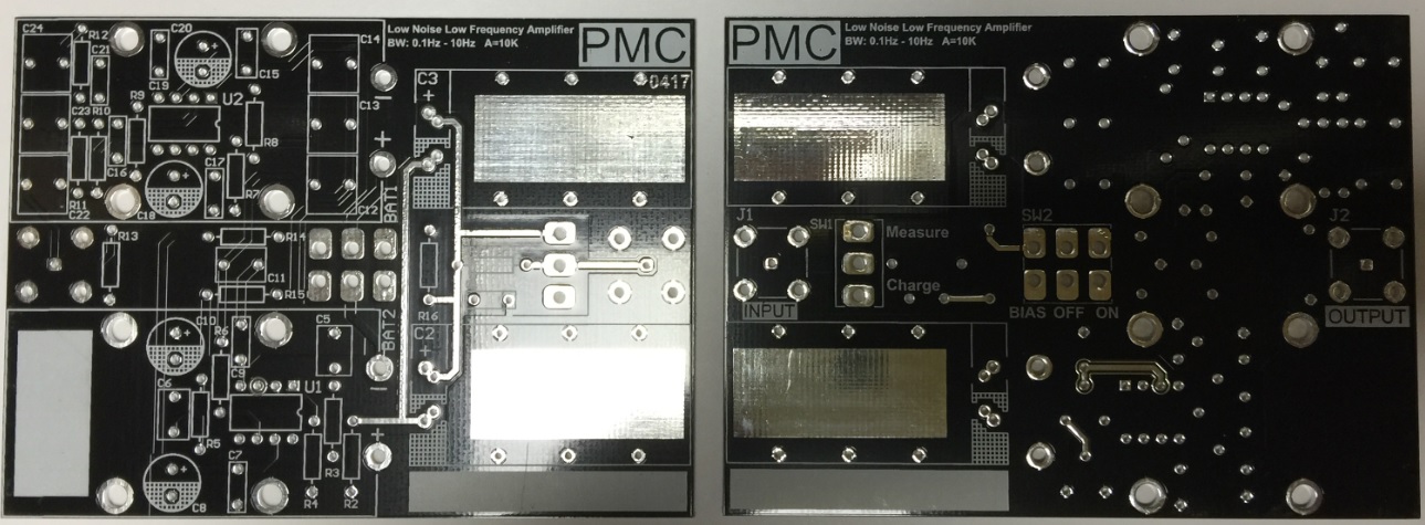
PCBs populated with all components, except the input capacitors.
A few words about components used:
-All resistors are 1% or 0.1% metal film
-0.1% resistors are Vishay MPR24 or Welwyn RC55
-All film capacitors are WIMA MKS2
-ICs soldered directly to PCB; no sockets used

Input capacitors were selected from a lot of 70 pieces from different manufacturers (Rubycon PK series, Wurth Elek. WCAP-ATG8 series, ELNA RE3 and RA3 series) and sources such as Farnell, Mouser and eBay (yes, I know that I probably bought some fake capacitors from eBay sellers…).
Capacitors were connected to a PSU set to 80% of nominal voltage and left “soaking” for approximately 3 days.
Then, they were individually measured for leakage using a Keithley 2450 SMU set to source 10V and measure current. After 12 hours, the leakage current was noted.
From tested lot, Rubycon PK series yielded the best results.
Selected capacitors for PCB #1:
Rubycon 35PK2200MEFC16X25 - 2,220uF 35V (Measured 1,859uF@120Hz) – Leakage 5.7nA@10V after 12h
Rubycon 35PK1000MEFCT810X20 - 1,000uF 35V (Measured 833uF@120Hz) – Leakage 3.8nA@10V after 12h
PCB #2:
Rubycon 35PK2200MEFC16X25 - 2,220uF 35V (Measured 1,840uF@120Hz) – Leakage 5.5nA@10V after 12h
Rubycon 35PK1000MEFCT810X20 - 1,000uF 35V (Measured 839uF@120Hz) – Leakage 3.9nA@10V after 12h
I decided to shield the capacitors to reduce EMI. This is probably not needed as the whole PCB is already shielded inside a grounded metal enclosure.
Capacitors were insulated with a couple of layers of Kapton tape and then wrapped in copper tape.
When assembled on the PCB, a wire loop “presses” the capacitor against the large exposed copper area in the PCB, connecting the shield to circuit ground.

Finally, capacitor pins were soldered to the PCB while clamped by an hemostat, to prevent heat from reaching capacitor’s body.
This is fully assembled PCB, ready to go inside the enclosure:

A fully assembled amplifier, ready for testing.
The very crude front panel is just a laminated piece of plain paper, printed on a laser printer.

Next steps:
-Electrical test
-Performance verification
Pedro Couto


