Author Topic: Keithley 2001 DVM factory modifications to work with a K1801 nanovolt preamp  (Read 52255 times)

0 Members and 1 Guest are viewing this topic.

Offline chuckbTopic starter

  • Frequent Contributor
  • **
  • Posts: 340
  • Country: us
Does anyone know what Keithley does to modify a K2001 or a K2002 to allow it to work with a Keithley 1801 nanovolt preamp? There is a factory mod that needs to be performed when these meters are used with a K1801 preamp.

I recently purchased a K1801 preamp on Ebay. The interconnect cable and the power supply card were not available from the seller or Keithley. The K1801 manual has a schematic so I am using that to lay out a pcb and build a the k1801 power supply card to get this all working. Should be a fun exercise.

Thanks
 

Offline ManateeMafia

  • Frequent Contributor
  • **
  • Posts: 730
  • Country: us
I believe you can enable it through the secret menu options. Similar to adding the extra memory. I am pretty sure I seen it in there.
 

Offline TheSteve

  • Supporter
  • ****
  • Posts: 3748
  • Country: ca
  • Living the Dream
I can verify the preamp option appears and gives the option to enable it in the secret menu on my 2001.
VE7FM
 

Offline TiN

  • Super Contributor
  • ***
  • Posts: 4543
  • Country: ua
    • xDevs.com
So it was you, who snagged it. Eh, I was not quick enough to bid more  :scared:

Please, please, do post inner photo and better external photos of preamp. Few voltnut's here already commited to making DIY preamp board for K2001/2002's we have here.
/!\ Do not remove short from preamp input terminals to avoid ESD damage!

To get it all working, you need:
* Make own preamp supply board (which goes into option slot in DMM) with very quiet isolated PSU, I2C EEPROM to store preamp cal/gain data
* Make cable to interconnect preamp with your preamp board
* Ensure your meter have B-firmware.  :-DMM
* Plug preamp addon board into meter, initialize preamp's EEPROM by using secret menu, article here.

2001 have to have B-firmware, not A-firmware, as only B-firmware supports preamp functions. Model 2002 A-firmware is OK for preamp.
There are no modify to multimeters itself.  ;)

I'm ready to provide all support you need for this project, just keep it up, as it's pure rare animal.  :-+
If you feel complexity of doing all this is over the top - let us know, I'm sure we could do this project together.
« Last Edit: October 02, 2015, 04:26:27 am by TiN »
YouTube | Metrology IRC Chat room | Let's share T&M documentation? Upload! No upload limits for firmwares, photos, files.
 

Offline Zucca

  • Supporter
  • ****
  • Posts: 4306
  • Country: it
  • EE meid in Itali
Hi chuckb,

Welcome in the best forum for the Keithley 2001/2002 DMM!

I am hunting that K1801 since the 18th March 2015:

https://www.eevblog.com/forum/testgear/restoration-glory-of-keithley-2001-dmm/msg632100/#msg632100

unfortunately with no luck. Now your message give me a big hope. I am so excited you have that baby now.
Please open it up very carefully and make tons of pictures...

Very interesting project indeed!

PS: How much was your bid in Ebay? 1100$?  ::)
Can't know what you don't love. St. Augustine
Can't love what you don't know. Zucca
 

Offline chuckbTopic starter

  • Frequent Contributor
  • **
  • Posts: 340
  • Country: us
Wow! Thanks for all the info and support. Thanks for the info on the firmware. That's what I was looking for.

I already have two of the EM Electronics A10 preamps. One is from Ebay and I have not checked it out yet. The other one is powered from some NiCad batteries, solar cells and a 100 watt flood light. That should keep the leakage currents low! I really should update that to LED illumination some day. I'll send some data files of the zero noise if you would like.

I believe I paid $600 for the A10 preamp when I ordered it from England 15 years ago. You might check the price of the A20 preamp. It has digitally selectable gains so we could probably make it work with the K1801 power supply card that I'm building. (The A20 may be a K1801 preamp in a different package)

I also have an old (1970s) N2a nanovoltmeter from EM Electronics. It needs a little work but I don't have any info on circuit details. I should probably start by changing the PS caps. Get those nasty electrolytics out of there.

I believe these are all modern versions of the K148 nanovoltmeter. Reference the Keithley web site for the schematic. The K148 uses a mechanical chopper to turn the DC signal into an AC signal to feed to the step up transformer (1:100 ratio?). Then you can use normal electronics to amplify the signal and demodulate it. The transformer lets the input noise be 100 times less than the first stage amplifier noise. Nothing is free so the trade off is 100 time higher input current. But in most low noise applications that is not an issue. The newer versions probably use low resistance MOSFET transistors to do the switching.

I saw a very good design article for a chopper transformer nv preamp in The Review of Scientific Instruments back in the 90s. I'll try and find it. I had to go to the local college to look it up.

Does anyone have a download of the Calibration EEPROM on the K1801 preamp card? I think the meter will probably need SOMETHING loaded in memory before it will let me do a calibration. I don't know though.

Yesterday I ordered the two little transformers for the K1801 power supply PCB from Tektronix. Together they cost as much as the preamp! I did not want to spend the time to design new ones. I'll have to do a little reverse engineering after they come in so the next person does not have to pay that...

The last part I need to identify is the connector that goes into the K1801 preamp. It looks like a wide Ethernet connector. I'll get some pictures and more details over the week end. After I get the PCB laid out I'll let you guys know. Hopefully it will be done by the end of the year. If anyone wants a PCB blank I can order extras at that time or anytime.

I'll see about pictures this weekend. I don't know how far down I can disassemble it. You have to be careful with Mu Metal shields. If you stress (drop) it it can change it's annealing and shielding properties.

All my low noise projects have been on hold for the last few years while I built a new workshop. I should be able to move into it by the end of the year. This hobby gets expensive!
 
Again, thanks for the support, I'm sure I'll need it.
 

Offline TiN

  • Super Contributor
  • ***
  • Posts: 4543
  • Country: ua
    • xDevs.com
Happy to have you onboard.
What are you using all that nano-stuff for, if not a secret? You look serious into low-signal measurements.

I don't think need anything in EEPROM that goes in preamp card, as secret menu item initialize all data for you. Then after you calibrate it with usual meter's menu for preamp, it will write settings like gain and offsets into EEPROM.
That's what it does in secret menu for NVRAM option anyway, so I don't see why should be different.

If you can shred more light and photos on details, specially about Tektronix transformers parameters, that would be great help. All rest parts seem to be common.

I can make PCBs for you if that is needed.

As of connector, perhaps it's RJ50 or other RJ-type? There are 10p10c and 15p15c types on market, like here at Digikey, perhaps similar? I don't have any details , since best photo I saw is the one ebay pic of yours unit.

I've got Keithley 182-M, on which I did review just few weeks ago, so would be interesting to compare performance of both.
« Last Edit: October 02, 2015, 05:40:12 pm by TiN »
YouTube | Metrology IRC Chat room | Let's share T&M documentation? Upload! No upload limits for firmwares, photos, files.
 

Offline VintageNut

  • Frequent Contributor
  • **
  • Posts: 534
  • Country: 00
The Keithley 1801 is an EM Electronics A10 made to order for Keithley. traded some emails with EM recently.

It will be interesting to see your results!

working instruments :Keithley 260,261,2750,7708, 2000 (calibrated), 2015, 236, 237, 238, 147, 220,  Rigol DG1032  PAR Model 128 Lock-In amplifier, Fluke 332A, Gen Res 4107 KVD, 4107D KVD, Fluke 731B X2 (calibrated), Fluke 5450A (calibrated)
 

Offline chuckbTopic starter

  • Frequent Contributor
  • **
  • Posts: 340
  • Country: us
I pulled the covers from both preamps and took some pictures. While I had it open I did a little circuit tracing to figure out the connector pin out.

I hope these attachments come through.

Does anyone have the specs on a Teledyne 9491BJ Zener? It's in what looks like a power supply monitor circuit.

The back of the K1801 pcb has 'A10 K" printed on it. So yes it looks like a version of the A10 preamp became the K1801 preamp. As you can see there are two selectable filter caps and 3 gain setting resistors.

We are off to watch "The Martian".
 

Offline TiN

  • Super Contributor
  • ***
  • Posts: 4543
  • Country: ua
    • xDevs.com
Quote
We are off to watch "The Martian".
Enjoy :)

That's a good start.
You can upload fullsize photos to ftp.xdevs.com with logic doc and password docsite. No size of file type limits :)
I wonder what's inside the can.

Also if you can take PCB bottom side - would be great, as K1801's PCB is single-sided!
YouTube | Metrology IRC Chat room | Let's share T&M documentation? Upload! No upload limits for firmwares, photos, files.
 

Offline Zucca

  • Supporter
  • ****
  • Posts: 4306
  • Country: it
  • EE meid in Itali
chuckb

Thanks so much for the pictures! it is so interesting to have a look inside your K1801. I sign up for a board, it is a very interesting project!

take care,

Z
Can't know what you don't love. St. Augustine
Can't love what you don't know. Zucca
 

Offline chuckbTopic starter

  • Frequent Contributor
  • **
  • Posts: 340
  • Country: us
Transformer update.
The K1801 power supply card has two transformers. I ordered them from Tektronix and they arrived in under a week. They are not cheap.
These are both Ferrite POT style transformers in 18 mm x 11 mm packages. The bobbin foot print is given in the attached pdf.

TR-285B ($193), core material 3E2A.
Primary, wire dia 0.0315" with insulation, this may be 20 ga. DC resistance = 0.0033 ohms. This is 3.9 inches of 20 ga wire.
Secondary, wire diameter 0.004" over insulation (difficult to measure), this may be 38 ga wire. The secondary winding is center tapped so there are two identical windings. DC resistance for one of the two matched secondary windings is 10 ohms. This is 15.4 feet of 38 ga wire.

When 0.1V RMS at 4.8 kHz is applied to the primary, half of the secondary generates 11.2V RMS.


TR-286B ($393), core material 3E27.
Primary wire dia 0.004" over the insulation (difficult to measure), this may be 38 ga wire. The primary is center tapped. The DC resistance of each half of the primary is 1.55 ohms.
This would be 28.7 inches of 38 ga wire.

Secondary #1 winding. This wire is smaller than the primary. I measured 0.003", again, this is very difficult to measure. I broke one of the wires trying to measure it. It may be 40 ga. This output is center tapped. The DC resistance of half of the winding is 12.6 ohms. This would be 11.7 ft of 40 ga wire.

Secondary #2 winding. This stranded wire is 0.028" in diameter (22 ga?). The wire is insulated as it goes into the transformer. The insulated wire is 0.047" in diameter. It has a DC resistance of 0.0061 ohms. This would be 4.5 inches of 22 ga wire.

With 2 V RMS applied to half of the primary, half of Secondary #1 developed 3.4 V RMS. Secondary #2 developed 0.0715 V RMS.

The TR-286 Secondary #2 feeds the primary of the TR-285 transformer. This looks like a technique to reduce leakage currents to the preamp. Insulated wire is used to reduce capacitive coupling inside the transformer and a low voltage excitation AC of less than 200mv is used to reduce capacitive coupling some more.

Before anybody asks, no I do not plan to take the cores apart and actually count the turns of wire. I can't count that high... The core material was the big unknown for me. The transformer winding details can be determined through experimentation.

All resistance and voltage reading have been double checked but I may still have made a mistake. All wire gauges are my best guess.


I got distracted this week when my K2002 showed up. It was calibrated in Aug of this year!. All the resistances measurements above were performed with the K2002 using 4 wire leads, offset comp was turned off. The inductance of the transformers may have disturbed the offset comp operation. I checked the K2002 against my 1 ohm Thomson standard before testing. The meter has the A10 firmware and I will upload that as soon as my ROM reader arrives. All the chips have 2009 dates codes so it's a pretty new meter. I will be doing the MEM2 mod as soon as my next package shows up from Digikey.
 

Offline TiN

  • Super Contributor
  • ***
  • Posts: 4543
  • Country: ua
    • xDevs.com
Great, I'll make a preamp PCB then for attached footprints, following k1801 schematics, more or less. :)

Great to hear about your 2002. You officially have best and newest Keithley out here :) Looking forward for firmware.

You can dump cal data too just in case, it is in little 24C16s. It's little unconvinient, as there are two EEPROMs so I used Raspberry Pi with isolated I2C via ADUM2250 to read both chips while meter powered on and kept in RESET (test point tied to GND). I can post more details later, since my 3458A repair is on hold, waiting more xpensive parts :(.

Connector measurement:

« Last Edit: October 11, 2015, 12:12:54 pm by TiN »
YouTube | Metrology IRC Chat room | Let's share T&M documentation? Upload! No upload limits for firmwares, photos, files.
 

Offline TiN

  • Super Contributor
  • ***
  • Posts: 4543
  • Country: ua
    • xDevs.com
Testing I2C EEPROM with PREAMP config on addon port with K2001 B17:


:)
YouTube | Metrology IRC Chat room | Let's share T&M documentation? Upload! No upload limits for firmwares, photos, files.
 

Offline chuckbTopic starter

  • Frequent Contributor
  • **
  • Posts: 340
  • Country: us
I fired up an old A10 preamp to understand what it's noise floor is. This preamp is powered by two 12v, 1.2 AH Lead Acid batteries. Each battery feeds an LT1021-10 very low noise precision voltage reference. The outputs of the two independent regulators power the A10 preamp.

I have the A10 input shorted and the gain set to 1,000,000. So the 5nv of offset becomes 5mv. That is supplied to a K2000 for digitizing. The attached photos and plots show the noise performance over 4000 seconds, a little over an hour.

The bench temperature is measured and recorded to 0.001 deg C with an HP2804A Quartz Thermometer. Normal quartz crystals are cut to minimize frequency change with temperature. This quartz sensor is cut for a linear frequency change with temperature. There may be several degree C temperature variation around the bench but this information is supplied as a reference.

The raw (1 second sample) noise was averaged over 60 samples and displayed on the same graph. This shows the 1 minute average of noise was within 1 nVpp for over 30 minutes. That's pretty good.

I'm looking forward to comparing it to the K1801 preamp. Maybe I'll power it up with the batteries and see what happens.
 

Offline Zucca

  • Supporter
  • ****
  • Posts: 4306
  • Country: it
  • EE meid in Itali
chuckb Are you a E/E hobbist? That's a real good set up. Maybe I am missing the two VSupply to the A10 in the graph. I am sure the LT1021-10 has a very low drift, but it would be interesting to see if the drift in the A10 is correlated to the VSupply.
Can't know what you don't love. St. Augustine
Can't love what you don't know. Zucca
 

Offline Mickle T.

  • Frequent Contributor
  • **
  • Posts: 467
  • Country: ru
I has a similar setup with Keithley 2100 and EM Electronics N1a as preamp. Noise floor was 2 nV p-p without any filtering or averaging (time constant 0.25 sec). 300 pV p-p with a max filter setting (TC=40 sec).
 

Offline chuckbTopic starter

  • Frequent Contributor
  • **
  • Posts: 340
  • Country: us
I have collected a lot of nV equipment from ebay over the years. My day job is an EE at an aerospace company. My hobby is precision electronics. The day job does not have enough precision electronics work to satisfy me.
For voltage I have several nV preamps and several 7.5 digit and now an 8.5 digit DVM.
For frequency I have GPS stabilized Rb Frequency standards for 12 digits of stability. I got an HP 5370B frequency counter (12 digits,  20ps) for a good price from ebay a few years ago.

I shut down the air conditioner last night and ran the A10 preamp for 5 hours. Attached is the plot.
 

Offline Zucca

  • Supporter
  • ****
  • Posts: 4306
  • Country: it
  • EE meid in Itali
Thanks chuckb, we need people like you here! I am so glad you joined us.
Can't know what you don't love. St. Augustine
Can't love what you don't know. Zucca
 

Offline chuckbTopic starter

  • Frequent Contributor
  • **
  • Posts: 340
  • Country: us
zucca - Thanks for the welcome. There are not many people interested in this corner of the electronics world.
I did a little test this evening. There was a few nv shift in the A10 when I took the battery off of charge. The output of the LT1021-10 dropped 100uv when I took the battery off of charge. The gives my implementation of the A10 a power supply rejection ratio of over 90dB. It may be in the preamp and it may be in my wiring. Life is not easy in the nV world.

Micke T - Great performance from the N1a. I have an N2a but I have not had a chance to test it out yet. There is a connection for batteries but no batteries are installed. I have no manuals for this unit. One battery connector has 20v on it and the other has 6v. Any ideas on what type of battery it needs?


Offline z01z

  • Regular Contributor
  • *
  • Posts: 151
Connector measurement:
If you are looking for that connector, you can try these - the original Pancon one has been discontinued.
http://uk.farnell.com/harting/09-27-232-6801/socket-din41612-q-2-32way/dp/1313796?ost=1313796
http://uk.rs-online.com/web/p/din-41612-connectors/7706950/

I can vouch for the first one, as I'm using it in a home-made scanner card and it fits the counterpart fine, though it doesn't have the alignment notches.
 

Offline Mickle T.

  • Frequent Contributor
  • **
  • Posts: 467
  • Country: ru
chuckb - I have a N1a Service Manual from Ernest J. Moorey, but can't find any information about batteries. The measured voltage is 9-10 V.
 

Offline ManateeMafia

  • Frequent Contributor
  • **
  • Posts: 730
  • Country: us
z01z, thanks for the part numbers. Digikey also has the Harting. About $10USD ea.
 

Offline TiN

  • Super Contributor
  • ***
  • Posts: 4543
  • Country: ua
    • xDevs.com
z01z, thanks for the part numbers. Digikey also has the Harting. About $10USD ea.

This Hirose is 4.13  :P
YouTube | Metrology IRC Chat room | Let's share T&M documentation? Upload! No upload limits for firmwares, photos, files.
 

Offline ManateeMafia

  • Frequent Contributor
  • **
  • Posts: 730
  • Country: us
Hirose must not be as proud of their connectors as Harting.
 

Offline chuckbTopic starter

  • Frequent Contributor
  • **
  • Posts: 340
  • Country: us
I tried to get a factory manual after I got the voltmeter but none were available. I must have a power supply problem because my voltages are not symmetrical. I'll have to research that. Thanks

chuckb - I have a N1a Service Manual from Ernest J. Moorey, but can't find any information about batteries. The measured voltage is 9-10 V.
 

Offline chuckbTopic starter

  • Frequent Contributor
  • **
  • Posts: 340
  • Country: us
The N2a Nanovoltmeter looks very similar inside.
 

Offline chuckbTopic starter

  • Frequent Contributor
  • **
  • Posts: 340
  • Country: us
The continuing story of starting with just a K1801 preamp and assembling a complete system. Tonight - The interconnect cable, well one end of it.
TiN was correct it's an 8 pin RJ50 style connector. I used PN 520424-3 to work with the 24 ga wire in the unshielded CAT 5 cable that I had handy.

The correct tool and die to crimp this connector cost about $10,000 with a several week lead time. That price seems reasonable, ;) however the lead time was an issue for me. So I used a screwdriver that I had on the bench. The screwdriver blade is 0.215" wide and 0.030" thick. It could have been slightly less thick. I inserted the 8 wires, lined the screwdriver up with the first gold contact and thumped the handle a few times. Repeat 7 more times.

After I was finished I read the connector assembly documentation. It turns out I over thumped the contacts. When correctly positioned the contacts should be 0.270 +-0.003" above the back side of the connector. My contacts were 0.250", oops. The continuity is good even as I move the connector so just be careful if you try the screw driver assembly method. That what I get for not waiting a few weeks for the correct tool.

I finished assembling the connector with two metal shields and the rubber boot. It ended up looking very good. I could have used shielded wire but my A10 does not pick up noise on the output wires so I was not to worried about this cable.

Digikey has all the parts in stock.


Offline chuckbTopic starter

  • Frequent Contributor
  • **
  • Posts: 340
  • Country: us
Corrected the connector part number on this photo
 

Offline TiN

  • Super Contributor
  • ***
  • Posts: 4543
  • Country: ua
    • xDevs.com
Screw-crimping :) Was there, did that.

Since I don't think getting 600$-worth transformers is an option for many, here's proposed battery powered low-noise LDO supply, using pair Linear LT3042 (200mA, 0.8uV noise spec).


As chuckb mentioned, care should be taken to connect isolated supplies, since both LDOs are positive. Will see how it work.

LTSpice circuit

I took measurements of scan card and created keepout zone for out future preamp board :


Test board for power:

« Last Edit: October 15, 2015, 04:31:20 am by TiN »
YouTube | Metrology IRC Chat room | Let's share T&M documentation? Upload! No upload limits for firmwares, photos, files.
 

Offline chuckbTopic starter

  • Frequent Contributor
  • **
  • Posts: 340
  • Country: us
That regulator looks great! We might need provisions for an electrolytic on the input to dampen long lead wires to a battery. I see there is an MSOP package available, that might be easier to solder to.
 

Offline chuckbTopic starter

  • Frequent Contributor
  • **
  • Posts: 340
  • Country: us
Testing I2C EEPROM with PREAMP config on addon port with K2001 B17:

[
:)

I hacked an EEPROM onto a connector and got the preamp mode working also! Pin 13 needs to go to 5v as a CARD Detect signal for the processor.
I manually Calibrated the gain for the G=1k, G=10k ranges. They worked just fine. The meter would not accept the manual setting for the G=100k range. I could change the value but when I exited the mode it went back to a gain calibration of 1. It was very strange. Does it work on other meters?
 

Offline TiN

  • Super Contributor
  • ***
  • Posts: 4543
  • Country: ua
    • xDevs.com
I'll have to check. I tried yesterday pin13 trick, but prolly data in EEPROM did not play well, as on next power on meter detected card, but it showed it as usual scanner card, not a preamp, even tho I did "init" thru secret menu.
YouTube | Metrology IRC Chat room | Let's share T&M documentation? Upload! No upload limits for firmwares, photos, files.
 

Offline TiN

  • Super Contributor
  • ***
  • Posts: 4543
  • Country: ua
    • xDevs.com
Digital side of preamp supply card is routed  ;)
YouTube | Metrology IRC Chat room | Let's share T&M documentation? Upload! No upload limits for firmwares, photos, files.
 

Offline TiN

  • Super Contributor
  • ***
  • Posts: 4543
  • Country: ua
    • xDevs.com
PCB for K1801 preamp head in the works, not forgotten.

Digital section done, LDO section almost done. Hope to complete this week.  :-/O
YouTube | Metrology IRC Chat room | Let's share T&M documentation? Upload! No upload limits for firmwares, photos, files.
 

Offline lukier

  • Supporter
  • ****
  • Posts: 634
  • Country: pl
    • Homepage
I was going through various patents and came across this one:

https://data.epo.org/publication-server/pdf-document/EP14170592NWA1.pdf?PN=EP2809004%20EP%202809004&iDocId=7873105&iepatch=.pdf
(EP2809004)

I'm following this thread and I thought it might be of interest to the other forum members.

It seems that the HP 3458A ADC designer, now working for Keithley, is recently busy with nanovolt measurements :)
 

Offline chuckbTopic starter

  • Frequent Contributor
  • **
  • Posts: 340
  • Country: us
PCB for K1801 preamp head in the works, not forgotten.

Digital section done, LDO section almost done. Hope to complete this week.  :-/O

The board looks great!
 

Offline ManateeMafia

  • Frequent Contributor
  • **
  • Posts: 730
  • Country: us
Yes it does.

When you finish the layout and test the board, it would be great to discuss any layout strategies used in the design for newbies like myself.
 

Offline TiN

  • Super Contributor
  • ***
  • Posts: 4543
  • Country: ua
    • xDevs.com
You? Newbie? I smiled, that's good one. :-+

I plan to have article-worklog eventually, covering both layout, schematics and usage.
YouTube | Metrology IRC Chat room | Let's share T&M documentation? Upload! No upload limits for firmwares, photos, files.
 

Offline Zucca

  • Supporter
  • ****
  • Posts: 4306
  • Country: it
  • EE meid in Itali
newbies like myself.

You? Newbie? I smiled, that's good one. :-+

Eh eh, and what I should be? Anyway I believe this project will be a kiss ass one. I am available to split the cost of prototyping of whatever, just PM me.
« Last Edit: October 27, 2015, 02:25:34 pm by zucca »
Can't know what you don't love. St. Augustine
Can't love what you don't know. Zucca
 

Offline TiN

  • Super Contributor
  • ***
  • Posts: 4543
  • Country: ua
    • xDevs.com
Attached animated GIF of finished boardie  8)
YouTube | Metrology IRC Chat room | Let's share T&M documentation? Upload! No upload limits for firmwares, photos, files.
 

Offline ltz2000

  • Regular Contributor
  • *
  • Posts: 103
The Keithley 1801 is an EM Electronics A10 made to order for Keithley.

The layout of the Keithley 1801 posted by chuckb is a direct copy of the EM A10 old version. His A10 in the same photo seems to be a later layout.

Please, please, do post inner photo and better external photos of preamp.

Many years ago I got a badly damaged A10 amplifier and did some reverse engineering. Including the potted mu metal box, which was a real pain in the ass to open. I hope I can still find the documents. I don't promise that they are complete or correct, but it shouldn't be that difficult to fill in the gaps.
 

Offline ltz2000

  • Regular Contributor
  • *
  • Posts: 103
Many years ago I got a badly damaged A10 amplifier and did some reverse engineering. Including the potted mu metal box, which was a real pain in the ass to open. I hope I can still find the documents. I don't promise that they are complete or correct, but it shouldn't be that difficult to fill in the gaps.

A10 circuit:

 
The following users thanked this post: Mickle T.

Offline chuckbTopic starter

  • Frequent Contributor
  • **
  • Posts: 340
  • Country: us

TR-286B ($393), core material 3E27.
Primary wire dia 0.004" over the insulation (difficult to measure), this may be 38 ga wire. The primary is center tapped. The DC resistance of each half of the primary is 1.55 ohms.
This would be 28.7 inches of 38 ga wire.


I noticed the primary center tap of the TR-286B transformer had a third wire attached to it. If you look closely at the center pin in the picture there are two red wires and one green. The extra wire is a larger ga wire. My guess is that it connects to an internal pri-sec electrostatic shield. Maybe that's why this transformer costs twice what the TR-285B costs!


Offline TiN

  • Super Contributor
  • ***
  • Posts: 4543
  • Country: ua
    • xDevs.com
Hm, what did he got here...

-

-

-

Few fails here and there, as usual for first rev...

YouTube | Metrology IRC Chat room | Let's share T&M documentation? Upload! No upload limits for firmwares, photos, files.
 

Offline chuckbTopic starter

  • Frequent Contributor
  • **
  • Posts: 340
  • Country: us
Looking Good!
 

Offline TiN

  • Super Contributor
  • ***
  • Posts: 4543
  • Country: ua
    • xDevs.com
Hmm, meter can't remember card, and I2C transfers seem to do nothing.

On power on I get two errors, 516 (Installed option id lost) and -241 (Hardware missing).


Perhaps it does not like 24C16 I put on? Original K1801 board using 24C01.
I don't have so small EEPROM, I thought they same for addressing? :)
YouTube | Metrology IRC Chat room | Let's share T&M documentation? Upload! No upload limits for firmwares, photos, files.
 

Offline ManateeMafia

  • Frequent Contributor
  • **
  • Posts: 730
  • Country: us
Is pin 7 pulled low (write protect pin)? I see on the 1801 schematics it is marked NC. Atmel states it should be pulled low for R/W.
 

Offline TiN

  • Super Contributor
  • ***
  • Posts: 4543
  • Country: ua
    • xDevs.com
Yea, it's low.
Pretty sure I got this gotcha. Old-ass Xicor X24C01 does not have device address (one like 0xA0 in today's 24Cxx ROMs), it just takes all data directly. And that's what Keithley feeding into bus as well, which I though as pooling device addresses is actually ROM address following DATA to write.  :phew: Good idea for sabotage young players - just solder this little ROM on PCB and it will corrupt whole multidevice-I2C, making sure you would not get any devices accessable  :-DD


Pesky little selfish bastard. Now I regret that did not put little 8bit AVR MCU on there.  :P
And ofc Digikey does not carry this ancient stuff, so good ol bay friend... Let's see.

chuckb

Which EEPROM chip you used?
« Last Edit: November 16, 2015, 06:04:05 pm by TiN »
YouTube | Metrology IRC Chat room | Let's share T&M documentation? Upload! No upload limits for firmwares, photos, files.
 

Offline TiN

  • Super Contributor
  • ***
  • Posts: 4543
  • Country: ua
    • xDevs.com
Good night photo for now..

YouTube | Metrology IRC Chat room | Let's share T&M documentation? Upload! No upload limits for firmwares, photos, files.
 

Offline chuckbTopic starter

  • Frequent Contributor
  • **
  • Posts: 340
  • Country: us
I tested the On Semi CAT24C01 on a connector. I had to reinitialize it each time power was applied. It stored the 1k and 10k gain constants (or at least looked like it did) but it would not even accept the 100k gain constant.

The XICOR 1991 data sheet does not talk about I^2C data bus. The data sheet refers to Two wire data bus. WIKI says multiple chip addressing was added to the standard in 1992. I guess these meters were designed a long time ago.

I just grabbed an X24C01P Xicor EEPROM from ebay. $9 with shipping. Will be here next Monday.


Offline TiN

  • Super Contributor
  • ***
  • Posts: 4543
  • Country: ua
    • xDevs.com
Won 20pcs Xicor X24C01F on bay..
YouTube | Metrology IRC Chat room | Let's share T&M documentation? Upload! No upload limits for firmwares, photos, files.
 

Offline Macbeth

  • Super Contributor
  • ***
  • Posts: 2571
  • Country: gb
Won 20pcs Xicor X24C01F on bay..

You don't do things by halves, TiN. I just did a quick ebay search...

A seller in HK - "0 available /  20 sold"  :clap:

This is a predatory move, and you have cornered the market in X24C01Fs. I reckon you could give Randolph & Mortimer Duke a run for their money  :-DD
 

Offline TiN

  • Super Contributor
  • ***
  • Posts: 4543
  • Country: ua
    • xDevs.com
I would never thought I'd need by 24xx EEPROM on ebay, EVER! Never say never..
I did not knew they have 20 total, anyway :)
YouTube | Metrology IRC Chat room | Let's share T&M documentation? Upload! No upload limits for firmwares, photos, files.
 

Offline Macbeth

  • Super Contributor
  • ***
  • Posts: 2571
  • Country: gb
Oh just a quickie - do you have the board dimensions and the make and model for the Keithley scan card connector? I fancy making myself a more modern version of the TCSCAN for my 2000.
 

Offline TiN

  • Super Contributor
  • ***
  • Posts: 4543
  • Country: ua
    • xDevs.com
Well, my apology to folks who are not so well at soldering and don't have microscope... I used soldering iron only, but in few places it was tricky to do.
To solder DFN and TSSOP center pads I heated those pads from bottom and placed chip on top to get it aligned and soldered at bottom. To ensure best heat transfer I used beefy 4.2mm chisel tip.

Using same wide tip I soldered most of caps.

-


Then switched to 102SDLF0.4mm angled tip and soldered LT3090 and LT3042 DFN's pins and rest of 0603 packages. You need to be patience, as board have no thermal barriers :).

Here's crappy soldering result:

-

-

Checking if it have a chance to work... I don't have proper resistors yet, need order some first.

-

+8.5V LDO works (output 7.07V due to not right resistor to set Vout)
rest don't work :)

6 hours spent.

Macbeth

If you not in hurry, all docs will be posted after I get it all working[/b].
YouTube | Metrology IRC Chat room | Let's share T&M documentation? Upload! No upload limits for firmwares, photos, files.
 

Offline Macbeth

  • Super Contributor
  • ***
  • Posts: 2571
  • Country: gb
No hurry, actually I should have read the thread from the start as the connector is on the second page available from Farnell :-[

I can measure up for the board but always good to have someone elses template to work from  :-+
« Last Edit: November 17, 2015, 08:13:41 pm by Macbeth »
 

Offline TiN

  • Super Contributor
  • ***
  • Posts: 4543
  • Country: ua
    • xDevs.com
Fixed issues with LDOs, current limiting for negative LDO tied to negative Vin, not GND like on positive ones. Doh.  :palm:

Two 9V Lithium 6F22 accumulators hooked up on power input and output. No load connected.

Positive 8.5V LDO (they all adjustable, I call them this just for clarity, following schematics) = +7.917V output, taking 4mA idle
Negative 8.5 LDO = -7.772V output, taking 1.8mA idle
Positive 5.0V LDO = 5.006V output
Negative 5.0V LDO = -4.910V output

Voltage is set by resistors on pins, so don't worry about voltage levels, they are not important at this moment. I used random jellybean 5% resistors to match up with output voltages. Final will have proper 25ppm 1% ones. Here's are some scope shots with 8.5V voltages connected via direct 1:1 BNC cable:

-

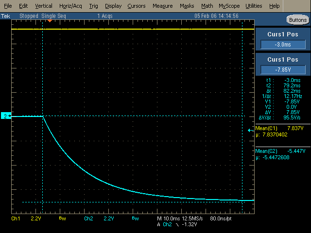
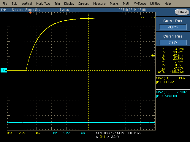
Start-up positive supply (left), negative supply (right)

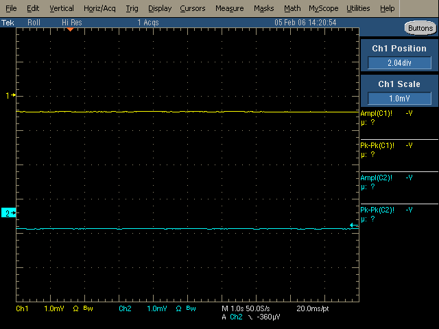
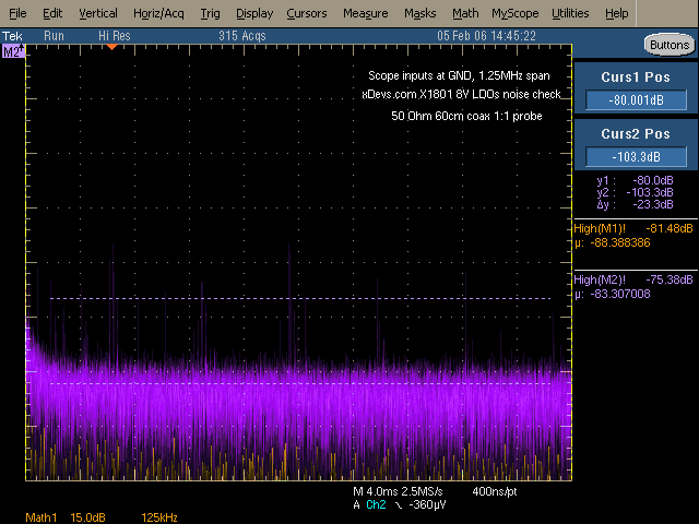
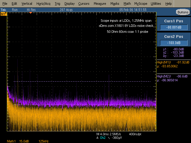
Noise measurement, scope is AC coupled, minimum voltage scale (1mV/div, TDS5034B), impedance set to 50 Ohm


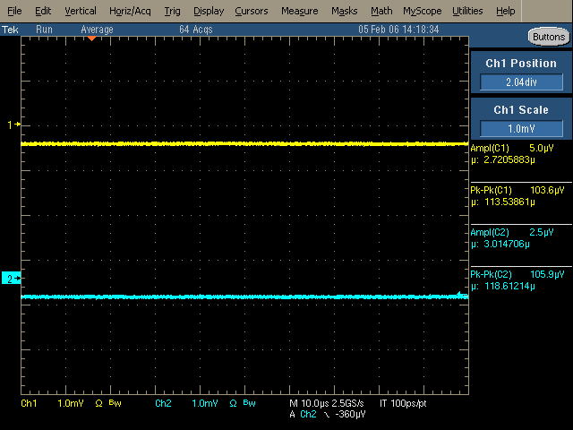
You see anything? I don't see. Scope shows exactly same with inputs grounded. No surprises, noise well below measurement levels on usual gear :)


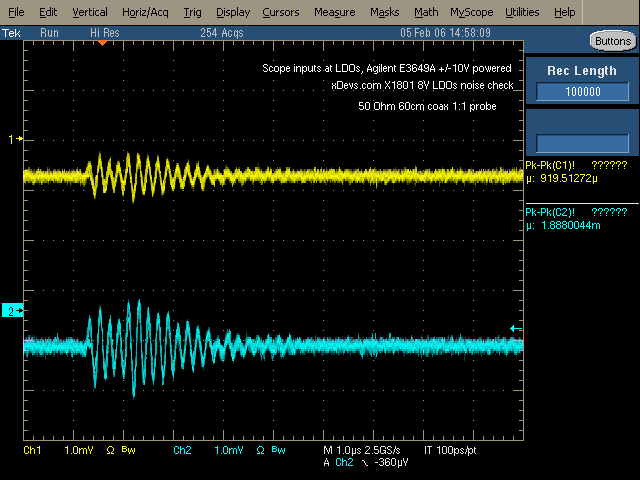
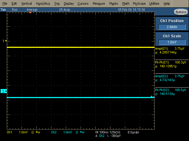
1 second scale, same story. Right capture - LDO input power is taken from Agilent E3649A ±10V. PSU causing ~1mV ripple on positive, and ~2mV on negative output. Could be wiring antennae though, did not re-check.


Now need get those pesky EEPROMs, order rest of parts and we can unbox preamp module and try some real stuff.  8)
YouTube | Metrology IRC Chat room | Let's share T&M documentation? Upload! No upload limits for firmwares, photos, files.
 

Offline ManateeMafia

  • Frequent Contributor
  • **
  • Posts: 730
  • Country: us
I see you are running the 3458A without top covers. Does this have something to do with your drift issue or is that blue cable monitoring something?
 

Offline TiN

  • Super Contributor
  • ***
  • Posts: 4543
  • Country: ua
    • xDevs.com
Yes and no :) Blue coax was A9 output monitoring. All the drift results were with covers on.
YouTube | Metrology IRC Chat room | Let's share T&M documentation? Upload! No upload limits for firmwares, photos, files.
 

Offline chuckbTopic starter

  • Frequent Contributor
  • **
  • Posts: 340
  • Country: us
I tested the On Semi CAT24C01 on a connector. I had to reinitialize it each time power was applied. It stored the 1k and 10k gain constants (or at least looked like it did) but it would not even accept the 100k gain constant.

I just grabbed an X24C01P Xicor EEPROM from ebay. $9 with shipping. Will be here next Monday.

The XICOR X24C01P arrived early today. I just installed it in a socket on a bare connector. NOW the meter remembers that it has a preamp between power cycles! However when I manually store the gain constants they return to 1.000 between power cycles. I still can't manually set and store the 100k Gain value. Maybe it needs a normal calibration first.


Offline TiN

  • Super Contributor
  • ***
  • Posts: 4543
  • Country: ua
    • xDevs.com
Based on my LA captures, meter does not write ROM if you just change gain values, it only does so after calibration or GPIB command ...SAVE from 1801 manual.
YouTube | Metrology IRC Chat room | Let's share T&M documentation? Upload! No upload limits for firmwares, photos, files.
 

Offline chuckbTopic starter

  • Frequent Contributor
  • **
  • Posts: 340
  • Country: us
I also have an old (1970s) N2a nanovoltmeter from EM Electronics. It needs a little work but I don't have any info on circuit details. I should probably start by changing the PS caps. Get those nasty electrolytics out of there.

I believe these are all modern versions of the K148 nanovoltmeter. Reference the Keithley web site for the schematic. The K148 uses a mechanical chopper to turn the DC signal into an AC signal to feed to the step up transformer (1:100 ratio?). Then you can use normal electronics to amplify the signal and demodulate it. The transformer lets the input noise be 100 times less than the first stage amplifier noise. Nothing is free so the trade off is 100 time higher input current. But in most low noise applications that is not an issue. The newer versions probably use low resistance MOSFET transistors to do the switching.

I saw a very good design article for a chopper transformer nv preamp in The Review of Scientific Instruments back in the 90s. I'll try and find it. I had to go to the local college to look it up.

Just an update on this comment.

I found the old article. It was in the March 1992 (Vol 63, No 3) issue of Review of Scientific Instruments, page 2089. "Low-noise preamplifier with input and output transformers for low source resistance sensors" by J. Lepaisant, et al.

They work through a very good analysis for a 100 pV / rt hz preamp with transformer coupling. This is the Johnson noise level for a 0.5 ohm resistor! We would need to add a chopper to the front end for DC operation.

Always on the lookout for new ideas...
 

Offline Zucca

  • Supporter
  • ****
  • Posts: 4306
  • Country: it
  • EE meid in Itali
Can't know what you don't love. St. Augustine
Can't love what you don't know. Zucca
 

Offline TiN

  • Super Contributor
  • ***
  • Posts: 4543
  • Country: ua
    • xDevs.com
Revive, revive!


Some goodies are here:


Will it crack? :)
YouTube | Metrology IRC Chat room | Let's share T&M documentation? Upload! No upload limits for firmwares, photos, files.
 

Offline TiN

  • Super Contributor
  • ***
  • Posts: 4543
  • Country: ua
    • xDevs.com
Assembly push-pull supply based on LTC3439 - Check
Assembly Xicor X24C01 - Check
Correct TVS directions - Check
Add connectors - Check
Test with 5V power from SMU - Check
Plug into meter - Check
Init preamp EEPROM - Check
Do dummy calibration - Check
Confirm preamp card is detected properly in 2001M B17 - check
Check preamp card in K2002 - Check (data is garbled though, perhaps 2002 use different format?)


Tests with real preamp head hopefully this week!
Need make few dividers to get microvolt outputs for calibration first!
« Last Edit: December 01, 2015, 04:37:17 am by TiN »
YouTube | Metrology IRC Chat room | Let's share T&M documentation? Upload! No upload limits for firmwares, photos, files.


Offline TiN

  • Super Contributor
  • ***
  • Posts: 4543
  • Country: ua
    • xDevs.com
I was trying preamp EM A10 today with 2002, but had very noisy readings.
Connected output of preamp to scope instead, got this:


287 Hz ripple. Turned off all lights and gear around, no difference. Preamp powered from 9V batteries (+/-8.5V measured). Tried 10Meg and 50 ohm at output, zero difference.
Cleaning board did not help either. :\
YouTube | Metrology IRC Chat room | Let's share T&M documentation? Upload! No upload limits for firmwares, photos, files.
 

Offline chuckbTopic starter

  • Frequent Contributor
  • **
  • Posts: 340
  • Country: us
I just checked my A10 and even with a gain of 10,000,000 it clean down to 1mV at those frequencies. I was expecting some chopping noise. The K1801 uses 488Hz. I don't know about the A10. I did notice some 30Mhz noise at 10mvpp. I will have to look into that.
 
I'm using +-12v lead acid batteries feeding LT1021-10 regulators.

What gain are you running? 20k?
 

Offline TiN

  • Super Contributor
  • ***
  • Posts: 4543
  • Country: ua
    • xDevs.com
I tried with gain 10k and 100k (feedback resistors 1k and 10k), the noise was exactly same.
YouTube | Metrology IRC Chat room | Let's share T&M documentation? Upload! No upload limits for firmwares, photos, files.
 

Offline chuckbTopic starter

  • Frequent Contributor
  • **
  • Posts: 340
  • Country: us
If I am remembering correctly, the internal feedback resistor is 1 ohm so the 1k resistor should provide a gain of 1000.
 

Offline TiN

  • Super Contributor
  • ***
  • Posts: 4543
  • Country: ua
    • xDevs.com
Mm, yes, sorry. So it's even lower gain then. I'll play with feedback cap (stock should be 10pF) to see if oscillations so away.
YouTube | Metrology IRC Chat room | Let's share T&M documentation? Upload! No upload limits for firmwares, photos, files.
 

Offline chuckbTopic starter

  • Frequent Contributor
  • **
  • Posts: 340
  • Country: us
Are you running the signals through the power supply pcb?

With battery power, the A10 can be a stand alone amplifier. I have operated the amplifier with a short across the input, battery power and connected the output directly to a K2000. Just set the y=mx+b scaling to 0.0001 if you use a 10k feedback resistor.

I believe the A10 has internal protection if both supplies are not energized at the same time, to prevent lockup conditions. Still, sometimes it takes a minute for the A10 output to come off the rail voltage (4v) and settle at 0 volts.
Good Luck!
 

Offline TiN

  • Super Contributor
  • ***
  • Posts: 4543
  • Country: ua
    • xDevs.com
Exactly like you saying, two 9V batteries powering A10 via 10cm wires, inputs shorted with copper wire, output connected to scope via coax (tried with active probe, same result). Voltage settles around zero RMS with this oscillation in place after a minute warmup. It does not change over 10 minutes time.

If I supply 10uV, 100uV, 1mV from DC voltage standard, signal is properly amplified, but oscillation stays same (in both amplitude and frequency).
« Last Edit: December 28, 2015, 05:04:49 am by TiN »
YouTube | Metrology IRC Chat room | Let's share T&M documentation? Upload! No upload limits for firmwares, photos, files.
 

Offline TiN

  • Super Contributor
  • ***
  • Posts: 4543
  • Country: ua
    • xDevs.com
If I add 10-47u cap over feedback resistor, this ripple reduce tremendously.

Shorted amp input:


EDC MV106 output connected to amp input (10V range, output 0V):


Gain : ~1000 (1K resistor).


YouTube | Metrology IRC Chat room | Let's share T&M documentation? Upload! No upload limits for firmwares, photos, files.
 

Offline chuckbTopic starter

  • Frequent Contributor
  • **
  • Posts: 340
  • Country: us
That's good news. You could probably fit it inside the metal case to minimize noise pickup. How big of a non polarized cap do you have?
 

Offline chuckbTopic starter

  • Frequent Contributor
  • **
  • Posts: 340
  • Country: us
The feedback cap only has the 1 ohms resistor to work with so the cap needs to be huge (0.47ms time constant). A better way would be an RC filter on the output. A 1k ohm and a 1.0ufd plastic cap would give you twice the filtering (1ms TC) that you have now.

Do you know about the trick with some plastic caps? The terminal connected to the outside foil is indicated with a black band or solid bar on the end of the capacitor. You connect that end to your lowest impedance node to minimize noise pickup. I see it on maybe 10% of the plastic caps I work with.

If I had to guess, based on the A10 schematic from LTZ2000 a few months ago, the output integrator cap has broken. I have not traced out my A10 pcb yet but that may be outside the metal can so it could be repairable. But I'm just guessing.

If you need to compare any voltages or waveforms just let me know and will tear down my amp.

I fixed my 30 Mhz osc issue with a few 0.1ufd caps on the LT1021-10 power supply outputs.
 

Offline TiN

  • Super Contributor
  • ***
  • Posts: 4543
  • Country: ua
    • xDevs.com
That's already with 47uF 63V non-polarized cap inside chassis. It just hanging over precision 1K wirewound resistor.
I don't have much of film caps yet, still looking into digital controlled gain circuitry, so I'll get some for filter as well next year.

This was more like quick try, so I need to put more time and efforts into it, before I ask for comparison or measurements.
Btw, condition are same either battery +/-9V powered or from LT3043/LT3090 on our power card module. One of reasons why I wanted to get A10 going, is to measure noise of power card module, as scopes I have aren't able to go below 2mV/div, on which noise is non-measurable.

P.S. I wanted to be 100% that LDO section works perfect, so you'd have trouble-free unit for testing. Obviously Keithley transformer part I'm not able to test, so it's bit tricky. Module + some bare ones goes on Jan 4, will need only transformers to be populated and tested.
YouTube | Metrology IRC Chat room | Let's share T&M documentation? Upload! No upload limits for firmwares, photos, files.
 

Offline alanambrose

  • Frequent Contributor
  • **
  • Posts: 377
  • Country: gb
BTW do you guys have the pin-out for the 32 way connector into the Keithley? I would like to build some custom switching matrices.

TIA, Alan
“A foolish consistency is the hobgoblin of little minds"
 

Offline TiN

  • Super Contributor
  • ***
  • Posts: 4543
  • Country: ua
    • xDevs.com
Of course we do, what you think :). Related data is in my nV preamp draft article. I'll update some layout screenshots and 3D CAD with keepouts next days. Beware pin numbering for connector :).

Are you going to opensource your design too? I have original TCSCAN-2001 but one can never have enough channels.
« Last Edit: February 04, 2016, 03:52:19 pm by TiN »
YouTube | Metrology IRC Chat room | Let's share T&M documentation? Upload! No upload limits for firmwares, photos, files.
 

Offline plesa

  • Frequent Contributor
  • **
  • Posts: 965
  • Country: se
Thats really good idea, PCB should be compatible with few relay types ( low emf, low leakage ). I assume that number of channels will be limited by Keithley cards supported in FW.
 

Offline z01z

  • Regular Contributor
  • *
  • Posts: 151
Did you know that in the older scan manuals you can also find schematics? It's a great starting point.
Apparently there are 2 ID pins on the connector, maybe changing their wiring changes the number of channels. Does anybody know what the different combinations mean?

When I was checking out relays for my home-made scanner board, I've realized that the pinout and pin positions are quite different for various relays. I also had this idea of having a PCB that can hold more that one type but gave up on it in the end. This might be possible for different relay types of the same manufacturer though.
 

Offline alanambrose

  • Frequent Contributor
  • **
  • Posts: 377
  • Country: gb
>>> Are you going to opensource your design too? I have original TCSCAN-2001 but one can never have enough channels.

Ah just got back to this thread. Thanks, and yes, of course.
“A foolish consistency is the hobgoblin of little minds"
 

Online doktor pyta

  • Frequent Contributor
  • **
  • Posts: 488
  • Country: pl
To chuckb,

Do You have an access to LCR bridge to measure the inductance of windings?
This will give precision info about turns ratio...

P.S. In famous "Low-Noise Electronic Design: C. D. Motchenbacher, F. C. Fitchen" book I read that:
'Do not check the dc continuity of any of the transformer windings
unless they can be adequately demagnetized!'
and
'
To measure the inductance of a low-level transformer accurately, use a
low-frequency impedance bridge with very small drive signals. Measure the
inductance at the lowest frequency used.
'

However Your transformers are ferrite core so they should be more resistant to that.

BTW. Here is the book:
http://www.pearl-hifi.com/06_Lit_Archive/14_Books_Tech_Papers/Motchenbacher_Connelly/Low-noise_Electronic_Design.pdf

Best Regards

Transformer update.
The K1801 power supply card has two transformers. I ordered them from Tektronix and they arrived in under a week. They are not cheap.
These are both Ferrite POT style transformers in 18 mm x 11 mm packages. The bobbin foot print is given in the attached pdf.

TR-285B ($193), core material 3E2A.
Primary, wire dia 0.0315" with insulation, this may be 20 ga. DC resistance = 0.0033 ohms. This is 3.9 inches of 20 ga wire.
Secondary, wire diameter 0.004" over insulation (difficult to measure), this may be 38 ga wire. The secondary winding is center tapped so there are two identical windings. DC resistance for one of the two matched secondary windings is 10 ohms. This is 15.4 feet of 38 ga wire.

When 0.1V RMS at 4.8 kHz is applied to the primary, half of the secondary generates 11.2V RMS.


TR-286B ($393), core material 3E27.
Primary wire dia 0.004" over the insulation (difficult to measure), this may be 38 ga wire. The primary is center tapped. The DC resistance of each half of the primary is 1.55 ohms.
This would be 28.7 inches of 38 ga wire.

Secondary #1 winding. This wire is smaller than the primary. I measured 0.003", again, this is very difficult to measure. I broke one of the wires trying to measure it. It may be 40 ga. This output is center tapped. The DC resistance of half of the winding is 12.6 ohms. This would be 11.7 ft of 40 ga wire.

Secondary #2 winding. This stranded wire is 0.028" in diameter (22 ga?). The wire is insulated as it goes into the transformer. The insulated wire is 0.047" in diameter. It has a DC resistance of 0.0061 ohms. This would be 4.5 inches of 22 ga wire.

With 2 V RMS applied to half of the primary, half of Secondary #1 developed 3.4 V RMS. Secondary #2 developed 0.0715 V RMS.

The TR-286 Secondary #2 feeds the primary of the TR-285 transformer. This looks like a technique to reduce leakage currents to the preamp. Insulated wire is used to reduce capacitive coupling inside the transformer and a low voltage excitation AC of less than 200mv is used to reduce capacitive coupling some more.

« Last Edit: May 05, 2016, 01:44:59 pm by doktor pyta »
 
The following users thanked this post: DiligentMinds.com

Offline chuckbTopic starter

  • Frequent Contributor
  • **
  • Posts: 340
  • Country: us
doktor pyta
Thanks for the ideas! No, I don't have access to an LCR meter. That's on my list to finish out my lab.

TiN did a great job developing an alternate power supply for the 1801 preamp interface card. That's probably the easiest way to get a working system.

I will be posting the results of testing the 1801 preamp and TiN's interface card soon.

chuckb
« Last Edit: July 16, 2022, 01:42:20 pm by chuckb »
 

Offline chuckbTopic starter

  • Frequent Contributor
  • **
  • Posts: 340
  • Country: us
Here is some noise data I collected from a battery powered A10 preamp over the last month. The A10 preamp is very similar to the 1801 preamp produced by EM Electronics. I am collecting 1801 noise data right now and will have results later.

My A10 preamp is powered from two 10 AH 12v lead acid batteries. The batteries power two LT1021-10 preregulators to stabilize the + and - 10v power to the A10. The input of the A10 was shorted and the gain was set to 1,000,000 with a 1% metal film resistor. The output signal was digitized with a K2002 DVM set to average 100 samples. The preamp had a 2nv offset so the K2002 was working with a large 2mv signal. Also the K2002 was set on 8.5 digits and 100 NPLC so it did not contribute any noise to the measurement. A GPIB interface cable sent the data to a PC that runs a small HP VEE program to collect data every 30 seconds.

Because temperature change and temperature rate of change is a issue with nv measurements the preamp is inside two styrofoam containers. The inner container holds two preamps, 2 lead acid batteries, several lbs of metal for thermal mass and the temperature sensor for the HP2804A Quartz temperature sensor (0.0001 C resolution). The temperature sensor measure the temperature of the small metal enclosure around the A10 preamp. That container is wrapped with bubble wrap to minimize air currents. All of that goes inside a square container built with 2" thick styrofoam sheets (R-10). That seems to eliminate short term temperature changes even with the airconditioning cycling on and off. I still see temperature changes on a daily time scale.

Over the 25 days of the testing the preamp noise was constant at 0.5nVpp. The zero reading drifted inside a 2nv band as the preamp temperature changed 2 deg C. Not to bad.

What good is this kind of performance? Well, lower noise is always better...
If this was measuring the difference between two 10V JJ arrays the difference could be determined to better than 0.0001 ppm or 1e-10. With a little noise averaging and some simple temperature control of the preamp that performance could be 10 times better.


I was able to take a few days off from work so now the Keithley 1801 preamp card that TiN designed and manufactured is working and working very well. Thanks TiN! I will post that data later.


« Last Edit: May 22, 2018, 05:53:49 am by chuckb »
 
The following users thanked this post: EmmanuelFaure

Offline chuckbTopic starter

  • Frequent Contributor
  • **
  • Posts: 340
  • Country: us
To prepare the K1801 for it’s new life the 22 year old electrolytic capacitors were replaced. The new capacitors are higher voltage, higher temperature and have a very long rated life.

The original Rubicon 1000ufd 16v caps were replaced with 35v capacitors. These capacitors are in a 9v circuit so the 35v caps have a good margin. There were two smaller 100ufd, 16v caps. These were also replaced with 35v units. I chose large caps for long life but they were a little difficult to fit inside the housing.

It’s now ready to go for another 30 years or more.

A preamp interface cable was built using a 14 ft length of CAT 6 7 network cable. This has the advantage that all 4 wire pairs are foil shielded and there is an overall outer foil shield.
The 4 command lines were placed in two of the shielded pairs. The commands are 1k gain, 10k gain, 5ufd filter, 50ufd filter. These are simple +-9v dc signals. The +- 9v power lines were in another shielded pair. The preamp output and the ground reference were the last two signals to be placed in a pair. The overall shield was tied to preamp case on one end and to the isolated ground at the interface card.

TiN did a great job designing and building the interface card. He built one version using the original very expensive transformers. Then he designed another version to work with much less expensive transformers. I should have just waited for the second version! I did not use the bias current cancellation circuitry and so far it has not affected the noise readings or stability. The card was working in my K2001, the cable was built, now I just needed to plug it into the rare K1801 preamp. After triple checking voltages and my connector pinout I plugged it in and it worked fine.

Adding the preamp to the K2001 or K2002 adds several new ranges to the DVM. For example now there is a 20uV, 200uV, and a 2mV full scale range for DC volts. The new 2m ohm, 4 wire ohms range should read down to u ohms now.

I let the equipment warm up a bit and followed the factory calibration procedure. I used an EDC 521 calibrator monitored with a K2002 DVM to provide voltage to K262 Low Thermal Voltage Divider. Luckily I had a Keithley low thermal cable to connect the K262 to the K1801 preamp. The K2001 built in calibration procedure has you use a K262 divider so that worked out well. After the 20uV full scale calibration on the new 20uV range. The readings were spot on at 20.000 uV, even the negative full scale reading was right on. The calibration limit is about 1 nV because of the noise floor.

The 200uV range was just as accurate. The 2mV range would not calibrate. It looks like my K1801 has an issue above 0.5mv (0.5ma output stage current) on the x1000 gain range. Oh well, I'm just using it for the more sensitive ranges anyway.

More test data to follow but the K1801 noise data looks as good as the A10 noise data.

Thanks to TiN and others, it looks like this project was everything I hoped it would be.

 
« Last Edit: June 08, 2016, 02:47:01 am by chuckb »
 
The following users thanked this post: TiN

Offline chuckbTopic starter

  • Frequent Contributor
  • **
  • Posts: 340
  • Country: us
The battery powered A10 preamp and the K1801 preamp were both installed in the insulated containers. Data was collected for several hours. The K1801 has a little more noise than the A10 preamp. Both preamps were operating at a gain of 100,000 with the inputs shorted and floating. I plotted the raw data (30 second samples) and added a line that averaged 15 minutes of the data. I shifted the line 0.5 nV up so the two lines could be clearly seen.

The temperature smoothly changed -0.3 deg C inside the enclosure during this data run.

I'm a happy Voltnut. Two nV preamps that can discern a 0.1nV change!

« Last Edit: June 08, 2016, 02:46:23 am by chuckb »
 

Online doktor pyta

  • Frequent Contributor
  • **
  • Posts: 488
  • Country: pl
chuckb, thanks for sharing the measurement results !
P.S. When I wrote about measuring inductance of the transformers I was totally convinced that You have the signal transformer that are inside the "front-end magic can". Now I see these transformers are used in the power supply section.
Sorry for the confusion.

Offline TiN

  • Super Contributor
  • ***
  • Posts: 4543
  • Country: ua
    • xDevs.com
Long overdue update from my side, finally got the setup ready last night during impulse livestream session.


Modified EM A10 with three gain range switch resistors (100K, 10K, 1K) and pair of MOSFETs to add digital gain control to let it use with Keithley 2001/2002.
Next step is to move thing to K2002 and calibrate.

Now more difficult task - find a store to buy M3 copper nuts  ???.
« Last Edit: February 09, 2017, 05:03:15 am by TiN »
YouTube | Metrology IRC Chat room | Let's share T&M documentation? Upload! No upload limits for firmwares, photos, files.
 

Offline TheSteve

  • Supporter
  • ****
  • Posts: 3748
  • Country: ca
  • Living the Dream
Now more difficult task - find a store to buy M3 copper nuts  ???.

copper stock, drill, tap&die set - make your own perhaps.
VE7FM
 

Offline Vgkid

  • Super Contributor
  • ***
  • Posts: 2710
  • Country: us
Closest version of copper is brass(You could try it, but it would not be ideal). Lets see what a nanovolt source uses.
We will go with the Keithley 560. I recently lost a bid on the 181 that had popped up, forgot to up my bid. :-[  :phew:

I recognize those binding posts.
CSI Enhance go.


In the Keithley manual, it uses copper nuts, but it doesn't say how they are used.
nut-spade-nut
or
screw flange-spade-nut
------
Furthermore it says that if copper nuts are not available, then twist the wires around the binding posts.
Anyone own a Keithley 560, that they want to open up the shielded nanovolt divider portion. >:D
---Sorry for typo's I can't fall asleep.
« Last Edit: February 09, 2017, 07:13:27 am by Vgkid »
If you own any North Hills Electronics gear, message me. L&N Fan
 

Offline ManateeMafia

  • Frequent Contributor
  • **
  • Posts: 730
  • Country: us
Isn't the Keithley 7168 using generic screws to tighten the copper lugs?
You might try nylon washers with brass nuts and get good results.
 

Offline chuckbTopic starter

  • Frequent Contributor
  • **
  • Posts: 340
  • Country: us
TiN, congratulations on the mod!

Your 1801 Power supply / Interface card has been connected to a K1801 and running 24/7 since I started it up last year. It's working great!
 

Offline Vgkid

  • Super Contributor
  • ***
  • Posts: 2710
  • Country: us
Looking at other keithley microvolt meters. They sandwich the copper lugs between 2 brass nuts.
If you own any North Hills Electronics gear, message me. L&N Fan
 

Offline USMC_Spike

  • Regular Contributor
  • *
  • Posts: 83
  • Country: us
This is all really good stuff y'all.  I want to play too.

But Alas...My 2001 got hit on a deadly corner...and UPS
refuses to pony up for a costly new display.

So I'm in limbo until I can find a good working affordable display.
Hoping that is the only problem I'll find on a former working unit.

If you have any ideas....I'm all ears.

Spike
Cheers,

USMC_Spike
 

Offline ap

  • Frequent Contributor
  • **
  • Posts: 282
  • Country: de
    • ab-precision
The display of a 7001 scanner should fit. These often come cheap.
Metrology and test gear and other stuff: www.ab-precision.com
 

Offline TiN

  • Super Contributor
  • ***
  • Posts: 4543
  • Country: ua
    • xDevs.com
I'd listed to ap and buy 7001 with confirmed working VFD to replace the glass (FP PCBs not compatible directly).

Alternative - contact plesa member here, he got few new VFDs and was selling them at 100$ cost some time ago. Not sure if he have any left.
YouTube | Metrology IRC Chat room | Let's share T&M documentation? Upload! No upload limits for firmwares, photos, files.
 

Offline mimmus78

  • Supporter
  • ****
  • Posts: 676
  • Country: it
There is a guy in UK selling 50pcs 7001 on eBay. If you contact him I think you can get one very cheap.

Inviato dal mio Nexus 6P utilizzando Tapatalk


Offline rastro

  • Frequent Contributor
  • **
  • Posts: 388
  • Country: 00
...
So I'm in limbo until I can find a good working affordable display.
Hoping that is the only problem I'll find on a former working unit.

If you have any ideas....I'm all ears.

Spike

USMC_Spike;
Have you tried running the unit remotely over the serial port?  You could then at least verify operation.  adapt-improvise-and-overcome :-+

Also I've heard UPS is notorious for flatly rejecting initial clams.  It not too much time has elapsed you may want to challenge their response.
« Last Edit: February 21, 2017, 02:34:05 pm by rastro »
 

Offline USMC_Spike

  • Regular Contributor
  • *
  • Posts: 83
  • Country: us
Re: Keithley 2001 DVM factory modifications to work with a K1801 nanovolt preamp
« Reply #100 on: February 22, 2017, 02:03:10 am »
No I have not tried running it remotely via serial port.

I'm not sure How I'd do that.

If you don't mind helping, I don't know the protocol for getting one running
using the serial port.

?

Cheers,

USMC_Spike
 

Offline USMC_Spike

  • Regular Contributor
  • *
  • Posts: 83
  • Country: us
Re: Keithley 2001 DVM factory modifications to work with a K1801 nanovolt preamp
« Reply #101 on: February 22, 2017, 03:04:51 am »
rastro,

I went through all the user and services manual that were posted at
the top of this thread...or one of the thread for the military version
of these unit with schematics.

Nothing I found addresses how to use the Digital I/O.

Yes there are many commands etc for the GPIB and IEEE interface
but no information I've found for using the Digital I/O (serial port.)

I'm all ears for anyone.


...
So I'm in limbo until I can find a good working affordable display.
Hoping that is the only problem I'll find on a former working unit.

If you have any ideas....I'm all ears.

Spike

USMC_Spike;
Have you tried running the unit remotely over the serial port?  You could then at least verify operation.  adapt-improvise-and-overcome :-+

Also I've heard UPS is notorious for flatly rejecting initial clams.  It not too much time has elapsed you may want to challenge their response.
Cheers,

USMC_Spike
 

Offline TheSteve

  • Supporter
  • ****
  • Posts: 3748
  • Country: ca
  • Living the Dream
Re: Keithley 2001 DVM factory modifications to work with a K1801 nanovolt preamp
« Reply #102 on: February 22, 2017, 03:16:32 am »
For remote communication with a K2001 you will need to use GPIB, the digital IO connector is not a serial port.
VE7FM
 

Offline USMC_Spike

  • Regular Contributor
  • *
  • Posts: 83
  • Country: us
Re: Keithley 2001 DVM factory modifications to work with a K1801 nanovolt preamp
« Reply #103 on: February 22, 2017, 04:54:15 am »
Nuts.

No GPIB gear here :(  Thanks for the clarification though.
Cheers,

USMC_Spike
 

Offline plesa

  • Frequent Contributor
  • **
  • Posts: 965
  • Country: se
Re: Keithley 2001 DVM factory modifications to work with a K1801 nanovolt preamp
« Reply #104 on: February 22, 2017, 05:02:50 am »
Nuts.

No GPIB gear here :(  Thanks for the clarification though.

If you do not have GPIB adapter you can build GPIB from Arduino.
http://egirland.blogspot.cz/2014/03/arduino-uno-as-usb-to-gpib-controller.html

BTW 2001 will not work with front panel PCB disconnected (VFD can be dead).
Another alternative is to connect by any terminal to pins on VFD board.

« Last Edit: February 22, 2017, 05:06:12 am by plesa »
 

Offline rastro

  • Frequent Contributor
  • **
  • Posts: 388
  • Country: 00
Re: Keithley 2001 DVM factory modifications to work with a K1801 nanovolt preamp
« Reply #105 on: February 22, 2017, 03:29:25 pm »
Spike - Sorry for the confusion you're right.  I was thinking of the K2000 which has both RS-232 and GPIB. 
The principal still holds that you can test the system without a display using the GPIB interface. 
 

Offline USMC_Spike

  • Regular Contributor
  • *
  • Posts: 83
  • Country: us
The file is a JPG and its a wopping 2.2KB in size.

I get this message:

Well I can't paste this image either.

grrrrr.
Cheers,

USMC_Spike
 

Offline USMC_Spike

  • Regular Contributor
  • *
  • Posts: 83
  • Country: us
Maybe the error message will show up now:

Cheers,

USMC_Spike
 

Offline USMC_Spike

  • Regular Contributor
  • *
  • Posts: 83
  • Country: us
So, after a few more tried I am here:
at 426 KB, now less than 1/4 size.

Note the upper left side of the VFD,
that was from the impact, in the carton,
wrapped in 1 inch bubble wrap, with
packing peanuts around it.  THX UPS.


« Last Edit: March 20, 2017, 12:02:46 am by USMC_Spike »
Cheers,

USMC_Spike
 

Offline TiN

  • Super Contributor
  • ***
  • Posts: 4543
  • Country: ua
    • xDevs.com
I think repair discussion would fit better in this K2001 repair log thread.
YouTube | Metrology IRC Chat room | Let's share T&M documentation? Upload! No upload limits for firmwares, photos, files.
 

Offline USMC_Spike

  • Regular Contributor
  • *
  • Posts: 83
  • Country: us
Tin, Thank you for your suggestion.

I posted it there in the repair thread.

Anyone have any GPIB scripts?

I finally have an adapter...Prologix to USB.

But no experience with GPIB.
« Last Edit: March 20, 2017, 08:23:06 am by USMC_Spike »
Cheers,

USMC_Spike


Share me

Digg  Facebook  SlashDot  Delicious  Technorati  Twitter  Google  Yahoo
Smf