I am trying some measurement setups that involve co-ax cabling and a signal generator with 50ohm output impedance. Which of course results in distorted signals due to ringing and echoes and fairies and things. After some research (including videos like
I bought a couple of feed-through 50 ohm terminators and a couple of 2 watt, 50 ohm, 20dB attenuators. Then I fell down a rabbit hole.
Let me say that I am still trying to wrap my head around using dB ratios in voltage measurements. So maybe I misunderstood something. But everything I read indicated that 10:1 voltage ratio = 20dB. (as opposed to 10:1 power ratio would be 10dB.) Ahah, says I, simply buy 20dB attenuators and leave the scope input set to 10x. Simple, right?
Not so fast. After a lot of experimenting and head-scratching, I eventually discovered that the attenuators I bought seemed to be fairly accurate only when the scope input was set to 5:1, as below (channel 1, yellow is a 300MHz, 10x scope probe borrowed from my Tek 475 connected via BNC probe adapter to a BNC T, channel 2, purple, is the RG58 coax through the terminator and channel 3 is the Siglent probe that came with the scope connected via BNC probe tip adapter. Source is a Heathkit RF signal generator at 1MHz):

Note that with channel 2 set for 5x, the voltages are all within a few millivolts.
Even at 100MHz, the voltages are very similar, despite some phase-shifting due to differing cable lengths:
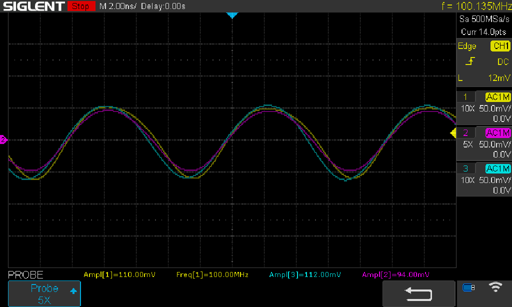
Thinking maybe the issue has something to do with the scope, I tried it out on the 475. Of course, it only has two inputs, so channel 1 is via the Tek probe and channel 2 is the attenuated coax cable. I shifted the traces apart 1 division for clarity on this old-school monochrome analog CRT. Note that the Tek probe has the identification ring but the BNC does not, so ignore the light on channel 2.
1Mhz:
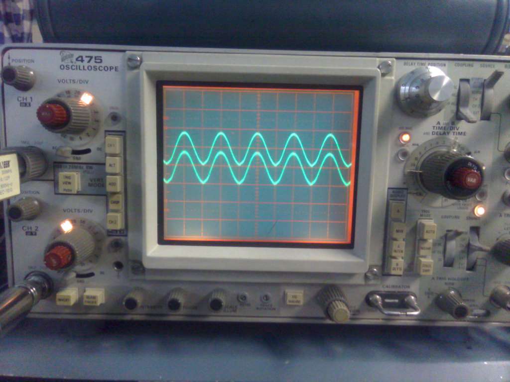
and 100MHz:

I next thought perhaps the attenuators were mis-labelled, however the resistance measured through the centre conductors is 81.4 ohms and from centre conductor to ground is 50.4 ohms. If I did the math right, that is very close to a 20dB, 50 ohm tee configuration, with the two R1 = 40.9 ohms crossing the Tee and R2 = 10.1 ohms leg to ground.
If my setup was somehow measuring power, then 20dB ssould equate to 100x, not 5x. If I put a 50 ohm terminator inline with the attenuator, then the voltage should halve so as to be 10:1, but the net termination would be 25 ohms, which kind of defeats the purpose, and the probes would also see 1/2 the voltage -- effectively 20:1.
What am I missing here???


