Author Topic: LM399/ADR1399  (Read 14400 times)

0 Members and 1 Guest are viewing this topic.

Online miro123Topic starter

  • Regular Contributor
  • *
  • Posts: 206
  • Country: nl
LM399/ADR1399
« on: October 20, 2021, 08:44:40 am »
Hello,
I've started an new software project.
it contains only four LM399.
The goals are
  - create model of each LM399
  - find best and worse of them
  - real time report of estimated voltages on each channel
  - much better performance than classical analog approach - averaging.

Project is more software related can be applied to multichannle LTZ1000. ADR1000s. I have limited knowledge in low level voltage measurements.- build two projects with ADS1256+PGA280 and just started with evaluating ADS125h02

Description is available @
https://github.com/mirtcho/LM399/wiki


Suggestions, remarks and critiques are welcome.

« Last Edit: October 20, 2021, 08:48:36 am by miro123 »
 

Online dietert1

  • Super Contributor
  • ***
  • Posts: 2074
  • Country: br
    • CADT Homepage
Re: LM399/ADR1399
« Reply #1 on: October 20, 2021, 05:28:58 pm »
Creating a Maxwell demon for voltage references is an ambitious project. You may need AI and a lot of example data for teaching it. Guess it starts by making one or more hardware setups to collect data. That is the state of my own work. I share your idea that similar methods will be applicable to different types of zeners. As Mr. Frank commented somewhere: "A good zener reference is constant but sometimes goes up or down by 0.1 ppm."
At the same time i know that all my setups contain errors, like connectors made of brass, imperfect Guard schemes and the like. The Arroyo temperature controllers i am using for some LTFLU references aren't perfect either. So it's important to keep up mood and resolve errors like the moving LM399 caps causing popcorn noise or RF from a WLAN router causing shifts.

Regards, Dieter
 

Offline Kleinstein

  • Super Contributor
  • ***
  • Posts: 14210
  • Country: de
Re: LM399/ADR1399
« Reply #2 on: October 20, 2021, 05:53:07 pm »
With LM399 reference I quite often see jumps between 2 discrete level, like an upper and lower level, but relatively little noise while at the level. So if one could know which level is currently present.

For the measurements I would consider to only read the difference of each reference relative to the average of some 4 (maybe more) references.
This would lower the demand on the ADC(s) and one could monitor multiple channels.
 

Offline DavidKo

  • Frequent Contributor
  • **
  • Posts: 295
  • Country: cz
Re: LM399/ADR1399
« Reply #3 on: October 22, 2021, 11:39:45 am »
I have checked the ADS1256 datasheet and I think that you cannot directly hook it to the reference (max input voltage should be+-5V) without divider.
 

Online miro123Topic starter

  • Regular Contributor
  • *
  • Posts: 206
  • Country: nl
Re: LM399/ADR1399
« Reply #4 on: October 22, 2021, 01:41:42 pm »
I have checked the ADS1256 datasheet and I think that you cannot directly hook it to the reference (max input voltage should be+-5V) without divider.
The ground between two parts is shifted with 4,5... 5V. On such way the LM399 7v comes somewhere  in the middle of ADS1256 range.
 

Online miro123Topic starter

  • Regular Contributor
  • *
  • Posts: 206
  • Country: nl
Re: LM399/ADR1399
« Reply #5 on: October 22, 2021, 01:48:39 pm »
With LM399 reference I quite often see jumps between 2 discrete level, like an upper and lower level, but relatively little noise while at the level. So if one could know which level is currently present.
Thanks for the input. This wil help me to build  LM399 model easier.
For the measurements I would consider to only read the difference of each reference relative to the average of some 4 (maybe more) references.
This would lower the demand on the ADC(s) and one could monitor multiple channels.
I don't understand this one. Why I need averaging? I would prefer to scale the setup from 4 to 8 independent channels instead of creating two -4*independent + 4 average. Average can be done in numeric way using the difference between signals.
 

Offline Kleinstein

  • Super Contributor
  • ***
  • Posts: 14210
  • Country: de
Re: LM399/ADR1399
« Reply #6 on: October 22, 2021, 02:54:26 pm »
The ADS1256 is a pretty good ADC, but the S/N is still not much better than the LM399 and one would still need a reference for the ADC.  I have done measurements with a LM399 ref as the DUT and another LM399 ref at the ADC. In this combination alone one never known which ref. is at fault. It needs at least a 3rd one. The ADC noise still is part of the noise - even with a pretty low noise ADC.

So the logical point would be to subtract some common voltage (some 7 V) from all the inputs. There would be only a small rest left for the ADC to sample and look at. For the 7 V to substract one would need a prettly low noise ref (e.g. ADR1000 or similar).
The average votlage of multiple LM399 in the test would be a pretty low noise reference, though still not perfect. If you than see a jump in one of the curves, it chould be pretty clear who is at fault, as one curve would see a jump up, while the others would see a smaller (1/3) step down.
 

Offline bsdphk

  • Regular Contributor
  • *
  • Posts: 200
  • Country: dk
Re: LM399/ADR1399
« Reply #7 on: October 22, 2021, 05:42:41 pm »
Look up "three cornered hat" in time/frequency measurement, you can do pretty much the same thing with voltages.
 
The following users thanked this post: arcnet

Online miro123Topic starter

  • Regular Contributor
  • *
  • Posts: 206
  • Country: nl
Re: LM399/ADR1399
« Reply #8 on: October 22, 2021, 08:02:07 pm »
The ADS1256 is a pretty good ADC, but the S/N is still not much better than the LM399 and one would still need a reference for the ADC.  I have done measurements with a LM399 ref as the DUT and another LM399 ref at the ADC. In this combination alone one never known which ref. is at fault. It needs at least a 3rd one. The ADC noise still is part of the noise - even with a pretty low noise ADC.

So the logical point would be to subtract some common voltage (some 7 V) from all the inputs. There would be only a small rest left for the ADC to sample and look at. For the 7 V to substract one would need a prettly low noise ref (e.g. ADR1000 or similar).
The average votlage of multiple LM399 in the test would be a pretty low noise reference, though still not perfect. If you than see a jump in one of the curves, it chould be pretty clear who is at fault, as one curve would see a jump up, while the others would see a smaller (1/3) step down.
Sorry for my criptic description. My point is that I don't measure the absolute value. Absolute value can be measured onece per month or year since I dont own 8 1/2 voltmeter.
I measure only the differences between signals - worse case 7mv difference  - I don't see any problem to use any multichannel SD ADC. CMMR shoud not me an probleem too since Vref signals are almost DC.  The project will be software and mathematics oriented
https://github.com/mirtcho/LM399/wiki
Short oversimplified description for 3xLM399
1. LM399 Vz re marked ad V1, V1,V3
2. the number of diferences is N=(n-1)*n/2 in our case n=3 N=3*2/2
3.diferences are V1-V2, V1-V3 and V2-V3
4. with simple mathematics you can judge who lies from them.

You can make many this only with difference of two Vref's . Eg V1-V2 = contains the spectrum noise of both Vrefs.
Statistics can help me to distinguish good from bad LM399 samples
With only power cycling one device I can build model of power off/on hysteresis of one device.
Ideas are endless.
I'm aware that proper HW setup is essential.  I don't have experience with measuring low level signals.  I have many qustions about my HW setup.
Lets start with first one.
What are the challenges of connecting  +4,5V output from LM399 power domain to the ADS1256 GND? ->     7V- 4,5V ~2.5V half ADC range


« Last Edit: October 22, 2021, 08:16:19 pm by miro123 »
 

Offline Kleinstein

  • Super Contributor
  • ***
  • Posts: 14210
  • Country: de
Re: LM399/ADR1399
« Reply #9 on: October 22, 2021, 08:37:39 pm »
Mesuring only the differences makes sense.

Shifting the ground of the ADC relative to the LM399's is OK. It needs some care about the power on and power of phase, to make sure the ADC input voltage don't leave the allowed range. The current from the positive side is naturally limited as there are only some 1 mA to drive to reference part. With a much lower voltage this may go up to maybe 2 or 3 mA, but this should still be OK in the safe range.
The 4.5 V to shift the supply should still be low noise, so more than just a TL431.  The ouput interface would also need to use the same ground as the ADC.
So this would be more like having a separate negative supply for the LM399 low side.

A possible configuration could be using the LM399 as a negative ref. relative to some +10 V. So the ADC would be at ground and there would be a common voltage or some +9.5 V  for the common positve side of the references. The ~2.5 V to ground would also be used to provide the zener current with a resistor each. It would be just the question on how to generate the +9.5 V (likely something like 1.3x times the average or one of the reference).


The following users thanked this post: miro123

Offline DavidKo

  • Frequent Contributor
  • **
  • Posts: 295
  • Country: cz
Re: LM399/ADR1399
« Reply #10 on: October 25, 2021, 07:25:46 am »
What about using some low noise LDO as LT3094 for negative voltage? https://www.analog.com/en/products/lt3094.html (to be true, I'm not sure if it has lower noise in reality - it should have 0.8uV RMS 10Hz-100kHz.


Online miro123Topic starter

  • Regular Contributor
  • *
  • Posts: 206
  • Country: nl
Re: LM399/ADR1399
« Reply #11 on: November 04, 2021, 12:19:54 pm »
I've started breadboarding and I've ran to the following problems
positive:
 10V5 voltage is running noise free
 10V5 voltage seems to stable - Voltage vs temperature. short term and one week stability within the specs of resistors
problems: All of them are 7V output related
 7V - I buffered the LM399 7V with the second opamp of OPA2188 - result noisy 7V015 output.I cannot measure the drift noise is +-50..60uV
 7V - I added filter group - R6=0 Ohm - C1=1nF - result no change @7v015 output
 7V - I added filter group R5=1k C3=220nF/COG - result slightly beter but still unstable 7V015 output.
 7V - added output filter R7=100 C4=1nF - short term /10minutes/ stability is OK. Noise/unstability is gone too. But still the One day and one week stability is worse than 10V5 output

I perform measurement with Agilent 34970A

I have no idea what goes wrong. I have few questions
  - Do I connect properly the 7V015 voltage buffer using OPA2188?
  - OP2188 is comming from alliexpress - can be an defective component? - still strange why 10V524 works just fine with the first opamp
  - Is there any LM399 reference design for 7V?

I forgot to mention that I power cycle the seup every day. Start temperature inside is 20deg at the morning 30 degree ~17:00h

Best Regards
Miro


« Last Edit: November 04, 2021, 01:12:43 pm by miro123 »
 

Offline Kleinstein

  • Super Contributor
  • ***
  • Posts: 14210
  • Country: de
Re: LM399/ADR1399
« Reply #12 on: November 04, 2021, 01:18:24 pm »
The overall circuit looks OK. The filtering at the input is a bit unusual, but should not cause trouble.

C1 and R6 would not have much effect with only 1 nF for C1.  To have an effect it would more like take 1-10 Ohms and 1 µF as suggested for the LM1399.
The LM399 should be ok with the small capacitor.
The filtering with R5 and C3 makes absolute sense.  One could consider to take -INA also from there.
With only 1 nF C4 has little effect though it does no hurt.

A point I am missing in the ciruit is supply decoupling also for the OPA2188.

It is absolutely possible to get defect or rejet parts from Aliexpress, though fakes are more common.
 
The following users thanked this post: miro123

Online Andreas

  • Super Contributor
  • ***
  • Posts: 3248
  • Country: de
Re: LM399/ADR1399
« Reply #13 on: November 04, 2021, 02:55:47 pm »
The overall circuit looks OK.

for me it looks very weird.

the Zener section is used as heater and the Heater is used as reverse polarized zener.
(usually pin 2+4 are the GND-Pins on LM399, and pin 1+2 belong to the zener)
with best regards

Andreas
 

Online miro123Topic starter

  • Regular Contributor
  • *
  • Posts: 206
  • Country: nl
Re: LM399/ADR1399
« Reply #14 on: November 04, 2021, 08:54:48 pm »
for me it looks very weird.

the Zener section is used as heater and the Heater is used as reverse polarized zener.
(usually pin 2+4 are the GND-Pins on LM399, and pin 1+2 belong to the zener)
with best regards

Andreas
Thanks for the remarks, At the breadboard they are connected properly. I've just begin learning Altium.
BTW I still don't know why they called LM399's "Zener" pins but don't call the LTC6555 "bandgap pins" :)
« Last Edit: November 04, 2021, 09:02:13 pm by miro123 »
 

Online Andreas

  • Super Contributor
  • ***
  • Posts: 3248
  • Country: de
Re: LM399/ADR1399
« Reply #15 on: November 04, 2021, 09:26:08 pm »
At the breadboard they are connected properly.
Strange. 50-60 uV I have only had on one device in my ageing box. Until I recognized that one of the heater pins was not within the socket. -> how much total current does your cirquit take? (Should be around 25 mA including Op-Amp at room temperature).

With best regards

Andreas
 

Offline RandallMcRee

  • Frequent Contributor
  • **
  • Posts: 541
  • Country: us
Re: LM399/ADR1399
« Reply #16 on: November 04, 2021, 10:13:30 pm »
. . .
I have no idea what goes wrong. I have few questions
  - Do I connect properly the 7V015 voltage buffer using OPA2188?
  - OP2188 is comming from alliexpress - can be an defective component? - still strange why 10V524 works just fine with the first opamp
  - Is there any LM399 reference design for 7V?

. . .
Best Regards
Miro


Personally, I would never use an opamp bought from Aliexpress (or Banggood, or Amazon, or...). The usual opamp for your purposes would be either the OPA2189 or the ADA4522-2.

You can get the OPA2189 for a reasonable price directly from TI. (ti.com). Tests here on the forum show it to be a good performer. Otherwise use Mouser or DigiKey.

 
The following users thanked this post: TiN

Online miro123Topic starter

  • Regular Contributor
  • *
  • Posts: 206
  • Country: nl
Re: LM399/ADR1399
« Reply #17 on: November 05, 2021, 07:12:13 am »

Personally, I would never use an opamp bought from Aliexpress (or Banggood, or Amazon, or...). The usual opamp for your purposes would be either the OPA2189 or the ADA4522-2.
I have changed the opamp with OPA2182 and problem disappears. That is what I have at home. I've bought 15pcs. of them from Mouser. All zero drift opamps are overkill for current breadboard. Isothermal zones are not optimal, no Hi-Z guards at all.

 
« Last Edit: November 05, 2021, 07:16:39 am by miro123 »
 

Offline r6502

  • Regular Contributor
  • *
  • Posts: 129
  • Country: de
Re: LM399/ADR1399
« Reply #18 on: November 05, 2021, 12:08:20 pm »
@Kleinstein

With LM399 reference I quite often see jumps between 2 discrete level, like an upper and lower level, but relatively little noise while at the level. So if one could know which level is currently present.

For the measurements I would consider to only read the difference of each reference relative to the average of some 4 (maybe more) references.
This would lower the demand on the ADC(s) and one could monitor multiple channels.

Do you have a reference for this - would be very interesting for me. What is the step height of the different voltage levels?

Guido
Science can amuse and fascinate us all, but it is engineering that changes the world - - Isaac Asimov
 

Offline maat

  • Regular Contributor
  • *
  • Posts: 144
  • Country: de
Re: LM399/ADR1399
« Reply #19 on: November 05, 2021, 01:14:23 pm »
Do you have a reference for this - would be very interesting for me. What is the step height of the different voltage levels?

Guido

I have attached a lovely sample of popcorn noise for you. The measurement was taking against a known good (LM399) reference using a KS 34470A. The output voltage of both modules is 10V. The popcorn noise in this case is about 0.5 ppm. Going through my logs of the last burn in run of about 50 LM399, I see about 0.25 ppm as the minimum and integer multiples of that number. The yield was typically about 60 % with no popcorn noise.
 
The following users thanked this post: r6502, oz2cpu

Offline Kleinstein

  • Super Contributor
  • ***
  • Posts: 14210
  • Country: de
Re: LM399/ADR1399
« Reply #20 on: November 05, 2021, 01:47:47 pm »
The steps I saw are around 3-4 µV, so some 0.5 ppm of the 7 V reference voltage. Different referencey showed a different frequency of the steps. I have one that get on average 1 jump per minute and another one that is more like 1 jump per hour - so one can get away without the jumps for quite some time. Attached is a measurement curve measuring 2 references relative to each other. The jumps are likely all from one of the references.
 
The following users thanked this post: r6502

Offline TiN

  • Super Contributor
  • ***
  • Posts: 4543
  • Country: ua
    • xDevs.com
Re: ADR1399
« Reply #21 on: November 16, 2021, 01:49:18 am »
Something showed up here to test.

YouTube | Metrology IRC Chat room | Let's share T&M documentation? Upload! No upload limits for firmwares, photos, files.
 
The following users thanked this post: branadic, syau

Offline branadic

  • Super Contributor
  • ***
  • Posts: 2390
  • Country: de
  • Sounds like noise
Re: LM399/ADR1399
« Reply #22 on: November 16, 2021, 07:08:00 am »
Quote
"Pictures or it isn't true."
  :-DD

-branadic-
Computers exist to solve problems that we wouldn't have without them. AI exists to answer questions, we wouldn't ask without it.
 

Online miro123Topic starter

  • Regular Contributor
  • *
  • Posts: 206
  • Country: nl
Re: LM399/ADR1399
« Reply #23 on: November 16, 2021, 08:15:57 am »
Creating a Maxwell demon for voltage references is an ambitious project. You may need AI and a lot of example data for teaching it. Guess it starts by making one or more hardware setups to collect data. That is the state of my own work. I share your idea that similar methods will be applicable to different types of zeners. As Mr. Frank commented somewhere: "A good zener reference is constant but sometimes goes up or down by 0.1 ppm."
At the same time i know that all my setups contain errors, like connectors made of brass, imperfect Guard schemes and the like. The Arroyo temperature controllers i am using for some LTFLU references aren't perfect either. So it's important to keep up mood and resolve errors like the moving LM399 caps causing popcorn noise or RF from a WLAN router causing shifts.

Regards, Dieter
I already start experiments with  6 channel prototype and I already start to struggle with small details :-)
1. From where do I get the PE -line? Do I need to make own PE?
2. Where to connect the Protective earth?- metal closet, insulation transformer

From where do I get me PE -line?
My whole setup is located in big metal closet = 2xHP3456+1xHP34960+1xPM2534+1X8842a + 6channel LM399/ADR1399 ready +ADS1256/STM32H743/ISO UART.
Power is delivered via 1KVA 230V/230V insulation transformer. Transformer itself has PE guard
3. Another question is where to put Raspberry PI? I use the Raspberry pi to collect processed data via isolated UART interface. The remote PC has acces via Ethernet port.

Enough questions for now.

As already mentioned the project is software based. The first step is to build reliable setup
Best regards,
Miro


« Last Edit: November 16, 2021, 08:34:19 am by miro123 »
 

Offline Kleinstein

  • Super Contributor
  • ***
  • Posts: 14210
  • Country: de
Re: LM399/ADR1399
« Reply #24 on: November 16, 2021, 08:30:33 am »
It is a bit unusual to use an extra isolation transformer. IFAIK the usual isolation transformers are build to power 1 consumer only. With more consumers connected it gets tricky with the protection and things can get worse than directly mains powered.

PE is mainly for protection against electrical shock and the earth found at the mains oulets or in rare cases with a separate connection. It depends if one actually has to connect the circuit to PE. In this case the references and ADCs would have no connection to the outside and may vrey well not need it, though it would not necessary hurt. There would be a transformer to power the references and ADC and STM32H... . Another (could also be the same, as the isolation is not absolutely needed, but it help with possibly EMI) transformer would likely power the Raspberry.
Ideally there would be a nearly closed metal case around the reference and ADC part with the case connected to the ciruit GND. This case could also be connected to PE, but it could also be isolated.
 

Online miro123Topic starter

  • Regular Contributor
  • *
  • Posts: 206
  • Country: nl
Re: LM399/ADR1399
« Reply #25 on: November 16, 2021, 09:08:11 am »
I added isolation transformer manly to filter medium frequency conducted EMI from the  grid. The HF is filtered from the common mode filter.
There are plenty of noise nowadays.
  - automatic street lighting systems - very dominant here
  - powerline communication.
  - all my home appliance  - Yest I already "upgraded" my home with class A++ BLDC refrigerator and washing machine :)
  - solar inverters - haply I'm the only one in the neighbor who has PV system

What are the problems if i connect many devices behind single insulation transformer?  I only know that inrush current & THD of consumers can be an issue. I can easily check this with power analyzer.


« Last Edit: November 16, 2021, 11:02:41 am by miro123 »
 

Online miro123Topic starter

  • Regular Contributor
  • *
  • Posts: 206
  • Country: nl
Re: LM399/ADR1399
« Reply #26 on: November 29, 2021, 04:29:14 pm »
Almost finishing the electrical part of breadboard.
Connection seems to work
6xLM399 -> ADS1256 -> STM32H753 ->ISO_UART-> rapsperry PI

The good news is that 6 LM399s are within 20mV range.  It is nice feeling to see ADS1256 entering areas  where is designed for - measuring small differential DC signals!
My knowledge and expertise lays in digital processing and embedded software. Still a lot of thinks ToDo  hardware related
To Do list
1. Finish mechanical part using the breadboard
2. Update Altium schematics
3. Make and order PCB
4. Mechanical tasks - a lot
============
Start finally with firmware /software.


« Last Edit: November 29, 2021, 04:47:13 pm by miro123 »
 
The following users thanked this post: Andreas

Online Andreas

  • Super Contributor
  • ***
  • Posts: 3248
  • Country: de
Re: LM399/ADR1399
« Reply #27 on: November 29, 2021, 06:42:15 pm »
Hello,

I would use sockets that better fit to the wire diameter of the LM399.
Better would be soldering direct to the PCB.

Btw: where did you get those NOS (National Semiconductor) LM399?

with best regards

Andreas
 

Online miro123Topic starter

  • Regular Contributor
  • *
  • Posts: 206
  • Country: nl
Re: LM399/ADR1399
« Reply #28 on: November 29, 2021, 07:13:15 pm »
Thanks for the tip.
I'm still in prototype phase. I will make final 4 layer PCB  then I will solder them. Circuit is AD1399 ready. Probably I will have two of them when PCB is ready. The plan to install two ADR1399 and 4 LM399.
NOS LMs are form eBay.I'm sure that they are original. I have internal information.  Personally I will not buy lm399 even if they are good one. ADR1399 seems the logical choice nowadays
https://www.ebay.com/itm/173362279991
« Last Edit: November 29, 2021, 09:35:51 pm by miro123 »
 
The following users thanked this post: Andreas

Offline oz2cpu

  • Frequent Contributor
  • **
  • Posts: 850
  • Country: dk
    • webx.dk private hobby and diy stuff
Re: LM399/ADR1399
« Reply #29 on: December 31, 2021, 07:03:25 pm »
Questions
the popcorn noise is normal for LM399 ? on almost all units ?
popcorn noise is compleetly gone in ADR1399 ? or just as normal ?
cant it be removed with a slow low-pass filter ?

please clarify ?
and also what device would you recommend of the two ?
they cost about the same, as far as i see

Radioamateur OZ2CPU, Senior EE at Prevas
EMC RF SMPS SI PCB LAYOUT and all that stuff.
 

Offline Kleinstein

  • Super Contributor
  • ***
  • Posts: 14210
  • Country: de
Re: LM399/ADR1399
« Reply #30 on: December 31, 2021, 07:25:54 pm »
The popcorn noise seems to be normal for the LM399. At least most units show popcorn noise. For the 4 units I tested so far the amplitude was about the same (some 4-5 µV) and just the frequency of steps different. From curves I have seen of other units the behavious fits that picture.
So from what I have see, expect a similar level of popcorn noise for >90% of the units.  One may get times of 1 hour without a jump, but this still does not mean no popcorn noise.

There is no way to filter the popcorn noise with a simple low pass, as the frequency can be very low (like on average around 1 min to 1 hour between steps). With multiple units here may be a chance to get some kind of detector to decide whether the refs are more in there upper or lower state. However chances are this would not be 100% reliable, but it could still reduce the uncertainy quite a bit.

Another way would be taking a histogram and than with enough time get 2 more frequent values and use the 2 values as reference point and not the average.

Besides the popcorn noise there may be other 1/f noise.

I would not expect the popcorn noise to be completely gone with the ADC1399, but the steps size should be smaller (e.g. 1/2)  to get the lower noie level and chances are the steps may be more frequent to get faster averaging.

The ADR1399 is supposedly quite a bit lower noise and chances are the stability can be similar. However so far there is naturally not as much data on long term drift so to be on the safe side with long term drift the LM399 would still be the best bet.
 

Online Andreas

  • Super Contributor
  • ***
  • Posts: 3248
  • Country: de
Re: LM399/ADR1399
« Reply #31 on: December 31, 2021, 07:33:39 pm »
Hello,

popcorn noise is normal (for all references).
Some samples have more others less (or even invisible) popcorn noise.
-> you should select the devices for low and rare popcorn noise.
Popcorn noise is random. Filtering is impossible since the time between events is unknown.
So even devices that have been tested with no popcorn noise may develop some at certain temperatures or over time.

The ADR1399 is relatively "new" so unknown long term behaviour compared with LM399.
The ADR1399 needs more zener current.
The ADR1399 has less 1/f noise.
The ADR1399 has less zener impedance and is more critical for oscillations.

So it depends on your needs.

with best regards

Andreas
 

Offline Kleinstein

  • Super Contributor
  • ***
  • Posts: 14210
  • Country: de
Re: LM399/ADR1399
« Reply #32 on: December 31, 2021, 07:42:03 pm »
Selecting for the frequency of the popcorn events is a 2 sided thing. On the short time the less often jumping ref looks better, but on a longer term average the more frequent jumping ref can be preferable, as the jump part can average out. It depends on the application which case of preferable.

The zener current for the LM1399 is higher, but it is still relatively low compared to the heater current. With the lower zener impedance the higher current does not translate to a more critical resistor to set the current.
 

Offline floobydust

  • Super Contributor
  • ***
  • Posts: 7007
  • Country: ca
Re: LM399/ADR1399
« Reply #33 on: December 31, 2021, 08:48:05 pm »
What is the ADR1399 oscillation mechanism? Datasheet:
"One of the trade-offs of achieving the much reduced dynamic impedance, however, is an increased sensitivity to direct capacitive loading. The LM399 was stable with practically any capacitive load.
The ADR1399 starts to ring with direct capacitive loads of more than a few hundred pF, and oscillates with 10nF direct. The ADR1399 is optimized for an external compensation series network of 5Ω and 1μF, as is shown in most of the typical application figures (see the Typical Applications section). If updating a legacy design with too much capacitance for the ADR1399, and there is nowhere to add a series 5Ω, try reducing the capacitance to less
than 1nF. Another single-element passive found to work directly with ADR1399 is a 10μF tantalum capacitor, even though the series ohms can measure less than 5Ω on an impedance analyzer."

If its zener has a much sharper knee, ADR1399 dynamic impedance 0.04-0.08Ω (but includes comp. network) compared to LM399 0.5-1Ω, where is the (greater) negative resistance coming from?
Oscillation issue with antique gas tube references like 0B2 adding a large capacitor >0.1μF across it causes oscillation, so only a small cap 0.01μF is used to attenuate HF noise. But this is due to Townsend avalanche multiplication.

I believe there was terrible disagreement here about having a large capacitor across a ref zener.  The minus was argued to be higher noise currents (capacitive discharge spikes) knocking out defect atoms in the lattice causing an aging issue. If my take on it is correct, it makes sense and the compensation network might then be a problem?
 

Online Andreas

  • Super Contributor
  • ***
  • Posts: 3248
  • Country: de
Re: LM399/ADR1399
« Reply #34 on: December 31, 2021, 08:49:06 pm »
Hmm,

My opinion is: you do not want to have any popcorn noise.

reason:
Popcorn noise is issued by impurities in the crystal structure.
https://e2e.ti.com/cfs-file/__key/telligent-evolution-components-attachments/00-14-01-00-00-80-75-78/Popcorn-Noise.pdf

The buried zener was invented to avoid impurities near the zener junction leading to less noise and more long term stability.
See Appendix A:
https://www.analog.com/media/en/technical-documentation/application-notes/an82f.pdf

So any device with excessive popcorn noise is a defective device.

With best regards

Andreas

« Last Edit: December 31, 2021, 09:12:03 pm by Andreas »
 

Offline Kleinstein

  • Super Contributor
  • ***
  • Posts: 14210
  • Country: de
Re: LM399/ADR1399
« Reply #35 on: December 31, 2021, 09:41:25 pm »
Popcorn noise needs some electronic (or maybe a dislocation ?) quatum state that has a large effect on the result. This could be an impurity (or maybe even vacancy) at a sensitive point, but it could as well be a surface state or isolated state in the oxide layer.
If the popcorn noise is with just 1 defect state, this could well be rather stable. If it moves the popcorn noise would change over time.

The LM399 and LM1399 don't have the zener ref directly at the output, but more like a shunt regulator. So the question of the output stability and sensitivity is more like comparable to a voltage regulator. Some LDOs like capacitance with ESR. If they have the capacitance with ESR, they can that also tolerate additional small capacitance without much ESR. The point is avoiding the near 90 deg phase angle for the load impedance in a certain frequency range.

So chances are high the LM1399 would also be OK with the 22 µF tantalum cap and 100 nF MLCC in parallel.
It is natural that with more capacitance the series resistance can be a bit smaller.

From the impedance curve in the LM1399 datasheet it looks still underdamped with 5 Ohms and 1 µF. So chances are a bit more than 1 µF would be good, espeically if the 1 µF is a MLCC with reduced capacitance due to the DC bias. So I would plan with 2 parallel foot prints for capacitor, just in case.
 

Offline branadic

  • Super Contributor
  • ***
  • Posts: 2390
  • Country: de
  • Sounds like noise
Re: LM399/ADR1399
« Reply #36 on: January 15, 2022, 07:32:38 pm »
Got some of these puppies too.

-branadic-
Computers exist to solve problems that we wouldn't have without them. AI exists to answer questions, we wouldn't ask without it.
 
The following users thanked this post: Andreas, ch_scr

Online miro123Topic starter

  • Regular Contributor
  • *
  • Posts: 206
  • Country: nl
Re: LM399/ADR1399
« Reply #37 on: January 15, 2022, 07:47:52 pm »
Me too. They are from the same batch 2113.
I wonder why there is a 9 months gap between production and shipment to the customers.
 

Offline Kleinstein

  • Super Contributor
  • ***
  • Posts: 14210
  • Country: de
Re: LM399/ADR1399
« Reply #38 on: January 15, 2022, 07:51:46 pm »
Me too. They are from the same batch 2113.
I wonder why there is a 9 months gap between production and shipment to the customers.
This could be one of the early batches and the data from dirft test may not have been there to decide if the chips are any good. The date could be the date of the wafer production - mounting to the case may have happend later.
 

Offline maat

  • Regular Contributor
  • *
  • Posts: 144
  • Country: de
Re: LM399/ADR1399
« Reply #39 on: January 16, 2022, 09:03:05 pm »
The game is afoot. I have got the next batch of LM399s and the two ADR1399 in the burnin test setup. :popcorn:
 
The following users thanked this post: TiN, Andreas, doktor pyta, Haasje93, MiDi, ch_scr

Offline maat

  • Regular Contributor
  • *
  • Posts: 144
  • Country: de
Re: LM399/ADR1399
« Reply #40 on: January 18, 2022, 12:39:52 am »
I was asked by Andreas  about the scanner card. The card is a replacement for the 2000-SCAN card for the Keithley 200x and DMM6500 series. The complete design files can be found over on Github: https://github.com/PatrickBaus/SCAN2000. The cable used is a Phoenix Contact 2926674 Dsub-50 breakout cable (https://www.mouser.de/ProductDetail/651-2926674).

It is based on the designs by fellow forum members cozdaz (https://www.eevblog.com/forum/projects/20-channel-diy-scanner-card-for-keithley-dmms-and-daqs/) and voltsandjolts (https://www.eevblog.com/forum/circuit-studio/example-project-20-channel-solid-state-scan-card-for-k2000-dmm/). The source code is inspired by George Christidis (https://github.com/macgeorge/SCAN2000STM32).

I did a redesign, because I wanted to use an STM32 MCU, as I use them on a regular basis at uni, so I do have all the SDKs ready and installed. Another thing was, that I wanted to replace some of the components to simplify sourcing them. Also I did not like the mechanical construction, because there was too much wear and tear on the guide rails in the DMMs. So I changed that as well.
The opto relays used are Toshiba TLP3558A (https://toshiba.semicon-storage.com/info/docget.jsp?did=60325&prodName=TLP3558A). These, I believe, are a very good compromise and can replace the original 2000-SCAN in almost all aspects.

The design is still a bit of work in progress. I do want to update a few final things:
  • Test it in a K2001 (our neighbouring) group has got one, I believe
  • Update the silkscreen to show the channels
  • Add a Python example to scan the DMM
I guess I will get all of that done by the end of the week.

Edit: I do still have a couple of PCBs left from my order. So if people are interested, I guess we can work something out.
« Last Edit: January 18, 2022, 12:46:23 am by maat »
 

Online daqq

  • Super Contributor
  • ***
  • Posts: 2302
  • Country: sk
    • My site
Re: LM399/ADR1399
« Reply #41 on: January 18, 2022, 02:06:51 pm »
Found this in my email newsletter. Link is to the normal non-SMD part: https://www.analog.com/en/products/adr1399.html?ADICID=EMAL_WW_P328165_MIX-NPI-PN_996&deliveryName=DM21110
Believe it or not, pointy haired people do exist!
+++Divide By Cucumber Error. Please Reinstall Universe And Reboot +++
 
The following users thanked this post: chuckb

Offline branadic

  • Super Contributor
  • ***
  • Posts: 2390
  • Country: de
  • Sounds like noise
Re: LM399/ADR1399
« Reply #42 on: January 18, 2022, 05:51:08 pm »
Must be either a marketing gag or a marketing flaw.

Quote
Pin-compatible LM399 replacement with improved performance"

Didn't know LM399 was available in a ceramic SMD package.

Edit: Seems like they are serious on that, wow.
https://www.analog.com/media/en/Other/Support/Customer-Service/ADI-Export-and-Import-Classifications.pdf

-branadic-
« Last Edit: January 18, 2022, 08:31:07 pm by branadic »
Computers exist to solve problems that we wouldn't have without them. AI exists to answer questions, we wouldn't ask without it.
 
The following users thanked this post: Mickle T.

Offline Noopy

  • Super Contributor
  • ***
  • Posts: 1735
  • Country: de
    • Richis-Lab
Re: LM399/ADR1399
« Reply #43 on: January 18, 2022, 08:54:30 pm »
A long time ago I have taken some pictures of the LM399 and the MAC199 (https://www.eevblog.com/forum/projects/lm399-die-analysis/msg2875790/#msg2875790) and tried to analyze the circuit. Now that I have a ADR1399 I first have to do an update on the LM399 and the MAC199. Putting the update in this topic here seems to be sensible.


Well you know the package.


Quite a big die for the small TO-46 package. (Yes, that´s an old picture.  ;D)


This picture is a little better than the old one. 199I stands for LM199, the variant with a higher temperature rating.


At the lower edge there are the revisions of six masks. One more revision marking is near the bondpad of pin 1. The arrow highlights bondpad 1.


The LM399 is a shunt regulator. The power part (blue) is built with a sziklai pair. The RC prevents oscillations. The 50R (green) is the emitter resistor for the sziklai pair. It is protected by Q10. If there is to much current flowing through the resistor the transistor opens a bypass.

Q3 (dark green) is the reference, the buried zener. The current necessary for the zener is determined by the 2k resistor.

The red part drives the sziklai pair. If the voltage across the terminals of the LM399 increases, the voltage across the 2k resistor is increasing, increasing the current through Q13, increasing the current through the sziklai pair and finally reducing the voltage across the terminals of the LM399. The RC prevents oscillations.

The pink part is a feedback biasing Q13. A voltage higher than 6,9V at the LM399 terminals gives you more current flow through Q13 and more current through Q16 too. The current mirror Q14/Q15 feeds the current into the node Q12/Q13 working against Q13 sinking current to lower the voltage across the LM399. This is probably for biasing Q13 into an ideal operating point. But it´s interesting that the bias increases with increasing deviation of the voltage across the LM399.  :-//


The shunt regulator is in the upper part of the die. In addition to the parts in the schematic you can find the diode between heater and regulator ground (green) and some more parts at the upper edge of the die (red).
The 10k at the base of Q13 can be tuned.


A nice starpoint supply.  :-+ The shunt regulator is connected to red/blue. The zener is supplied by yellow/green and the rest of the circuit is connected to pink/cyan.


Here you can see the additional circuit. T17 is hard to recognize. The right contact of the resistor R14 connects to the n-doped well too and acts as a collector for T17.


Tesla has copied the LM399 (MAC199). In the schematic of the MAC199 you can find the additional circuit (red). It looks like it is an additional current sink for the zener. T17 does some current limiting.
I have no idea why they integrated this circuit.  :-//


The buried zener diode…


The transistor Q16 is interesting. It seems it has a big and a small collector contact, four base contacts (two of them connected) and one emitter contact. A lot of options…


The Darlington pair Q1/Q2 (blue) is the heater. The green circuit is an overcurrent limiter.

The dark green circuit generates a reference current for the two current mirrors (red). Q7 biases the driver circuit. Q4 (pink) is the temperature sensor. With a higher temperature Vbe drops drawing more current of Q7 and reducing the current trough the Darlington stage.

Q5 supplies D1 with a constant current. The orange circuit supplies a voltage at start-up. Q8 isolates the start-up circuit as soon as the reference circuit is active.


At the lower edge there is the big transistor Q1 which consists of 21 transistors. It has to dissipate up to 5,5W. The 4R2 resistor of the current limiting circuit can be adjusted.

In the heater circuit you can find the diode ZD2 above the transistor Q2. The MAC199 schematic shows this diode. It lowers the potential of the transistor Q2 so it´s easier to drive it.

The temperature sensor Q4 is near the reference zener. The voltage divider 11k2/1k allows a lot of different connections which moves the desired temperature.

The combination Q8/Q9/D2 is integrated quite efficient.  :-+


In the first place I guessed the die is placed on an additional layer that protects the reference circuit from mechanical stress. Today I assume the rough edge is due to breaking of the wafer after sawing the upper part.


https://www.richis-lab.de/REF02.htm

 :-/O
 
The following users thanked this post: doktor pyta, SilverSolder, Gyro, BU508A, ch_scr, maat, eplpwr

Offline Noopy

  • Super Contributor
  • ***
  • Posts: 1735
  • Country: de
    • Richis-Lab
Re: LM399/ADR1399
« Reply #44 on: January 18, 2022, 08:55:40 pm »


Here comes the update for the MAC199.
Tesla has built the MAC199, the MAB399 and the MAE299. These are just binned variants of the same reference which allow different ambient temperatures. The MAC199 is specified for a temperature range of -55°C up to +125°C.


The MAC199 uses the same package type as the LM399 but the case is a little higher because the package is a little higher.


Looks like the LM399. There are just some small differences.


Here you can see some structures that show the mask alignment. And there is the logo Tesla puts on all of its circuits.


In the upper left corner you can see eight mask revisions. In the LM399 we just saw seven masks. Some of the masks were modified four times.


The buried zener looks quite the same as the buried zener in the LM399.


The circuit of the LM399 and the MAC199 are quite similar. As we have seen the red circuit is integrated in the LM399 too.
You can find the resistor R16 neither in the MAC199 nor in the LM399. It´s probably highly integrated in the dense area in the upper right corner, perhaps in the LM399 too.


The reference circuit looks pretty like the LM399.


But hey, there is a connection missing between T16 (yellow) and T15 (red). That´s strange...

By the way: T16 looks interesting. There are five base connections and four emitter connections.


Without the connection a lot of the circuit is dead. But it would probably still act like a reference. Probably a worse reference.


Looking closer you can spot some edges caused by the buried collector. It looks like the buried collector of T16 and T15 are connected.  :-+


The MAC199 heater schematic is more complete than the schematic of the LM399. Here we have the zener in the collector of the transistor T2. The emitter resistors of T1 are represented by R2.


The heater part on the die of the MAC199, nothing special…


The side of the die has the same structure as the side of the LM399 die. It is probably sawn a bit and then broken out of the wafer too.


https://www.richis-lab.de/REF02a.htm

 :-/O

...on my side it looks like the forum shows the old die overview and the mask revision pictures.  :-\ The new and better one are on my website. Perhaps you have to clear your cache.
« Last Edit: January 18, 2022, 08:59:20 pm by Noopy »
 
The following users thanked this post: Mickle T., doktor pyta, Gyro, BU508A, ch_scr, maat, eplpwr

Online magic

  • Super Contributor
  • ***
  • Posts: 6779
  • Country: pl
Re: LM399/ADR1399
« Reply #45 on: January 19, 2022, 10:20:11 am »
I always assumed that those trenches indicate location of holes where isolation dopant had been applied.


So there is no isolation diffusion between Q16, Q15 and Q14 on both versions of the chip and hence Q16 collector is connected with PNP bases through the whole thickness of the epitaxial layer.
The green/mustard border between transistors looks identical as NPN bases, suggesting it's surface processing. Maybe an effort to strengthen isolation diffusions, applied more or less automatically (and mindlessly) at some distance from active areas of all transistors.

Regarding T17, T18 - it's a current mirror. Of sorts. T17 sinks T14 collector current through R14. T18 base voltage is simply T17 base voltage, minus whatever is R14 voltage drop. Then there is some further resistance in T18 emitter.
It obviously provides additional bias to the zener and I can guess it's supposed to have some particular kind of variation with temperature. Similar tricks are found bandgap references.
 
The following users thanked this post: Noopy

Offline Noopy

  • Super Contributor
  • ***
  • Posts: 1735
  • Country: de
    • Richis-Lab
Re: LM399/ADR1399
« Reply #46 on: January 19, 2022, 11:03:59 am »
I always assumed that those trenches indicate location of holes where isolation dopant had been applied.

You are probably right.  :-+


So there is no isolation diffusion between Q16, Q15 and Q14 on both versions of the chip and hence Q16 collector is connected with PNP bases through the whole thickness of the epitaxial layer.

I agree with you.
But it would probably be a relevant resistance. With the buried collector you get a low resistance path.


The green/mustard border between transistors looks identical as NPN bases, suggesting it's surface processing. Maybe an effort to strengthen isolation diffusions, applied more or less automatically (and mindlessly) at some distance from active areas of all transistors.

Sounds reasonable.  :-+


Regarding T17, T18 - it's a current mirror. Of sorts. T17 sinks T14 collector current through R14. T18 base voltage is simply T17 base voltage, minus whatever is R14 voltage drop. Then there is some further resistance in T18 emitter.
It obviously provides additional bias to the zener and I can guess it's supposed to have some particular kind of variation with temperature. Similar tricks are found bandgap references.

T17/T18 is a current mirror? Sound strange...
As long as the base current of T18 is low enough and the resistor R14 is small enough T17 shouldn´t conduct anything. R14 looks like round about 3k. 100µA should be no problem.
Yeah, it´s probably some kind of compensation for something. Temperature should be constant but of course you can´t guarantee it´s always exactly the same value.

Offline Noopy

  • Super Contributor
  • ***
  • Posts: 1735
  • Country: de
    • Richis-Lab
Re: LM399/ADR1399
« Reply #47 on: January 19, 2022, 11:15:23 am »
Wait a minute! Now I see your point!
Since the supply is a current source T17/T18 behave like some kind of current source! You are right!  :-+
Thanks for your input!

Online magic

  • Super Contributor
  • ***
  • Posts: 6779
  • Country: pl
Re: LM399/ADR1399
« Reply #48 on: January 19, 2022, 04:55:41 pm »
The biasing of Q13 is another old trick. Each of those mirrors has an emitter resistor and more active area in the output transistor than in the input.

At low currents, more active area means more current for the same Vbe so the mirror's output is more than the input.
At high currents, the resistor drops serious voltage, Vbe of the output transistor decreases and its current is less than the input.
Equality is achieved at a particular current which causes output emitter resistor voltage to be the logarithm of the ratio of active areas, and the base of the logarithm depends on temperature.

In LM199:
Low voltage: Ic(Q13) < Ic(Q16) and Ic(Q14) > Ic(Q16) → output stage is pulled up (disabled)
High voltage: Ic(Q13) > Ic(Q16) and Ic(Q14) < Ic(Q16) → output stage is pulled down (enabled)

Observe that both Q13 and Q16 have a lot of potential emitters but only one is actually connected. It looks like some serious tweaking took place on the design stage.

Example sim attached. I can change transistor types and it behaves more or less the same.
 
The following users thanked this post: Noopy

Offline RikV

  • Regular Contributor
  • *
  • Posts: 130
  • Country: be
Re: LM399/ADR1399
« Reply #49 on: January 19, 2022, 11:01:23 pm »
Is there any information on the ADR1399 in ceramic HLS8 package? what is the exact reference number? Datasheet? specifications?
 

Offline Noopy

  • Super Contributor
  • ***
  • Posts: 1735
  • Country: de
    • Richis-Lab
Re: LM399/ADR1399
« Reply #50 on: January 20, 2022, 02:51:48 am »
...

The effort they have put in this circuit is amazing.
At a constant temperature you would assume that something like this would give you already a quite stable voltage:


Offline MiDi

  • Frequent Contributor
  • **
  • Posts: 600
  • Country: ua
Re: LM399/ADR1399
« Reply #51 on: January 20, 2022, 06:33:07 am »
Is there any information on the ADR1399 in ceramic HLS8 package? what is the exact reference number? Datasheet? specifications?

Not yet, but if there is, you will find it in specific ADR1399 HLS8 thread.
 

Offline Noopy

  • Super Contributor
  • ***
  • Posts: 1735
  • Country: de
    • Richis-Lab
Re: LM399/ADR1399
« Reply #52 on: January 21, 2022, 08:16:03 pm »


Now let´s take a look into a ADR1399!

Output voltage is 7,05V. The output impedance is lower than that of the LM399: 0,04Ω(typ) / 0,08Ω(max) vs. 0,5Ω(typ) / 1,5Ω(max).

The datasheet states a faster warm up time (0,1s vs. 2s). That´s interesting because the heater current is the same. Looking at the diagrams you see that the ADR1399 heater controller is just faster. There is a nice little overshoot while the LM399 heats slower but evenly.
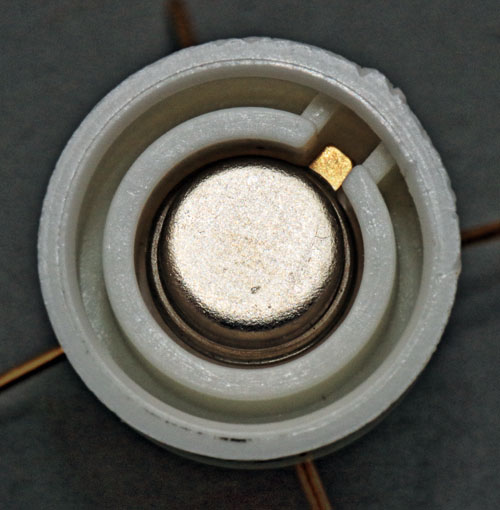
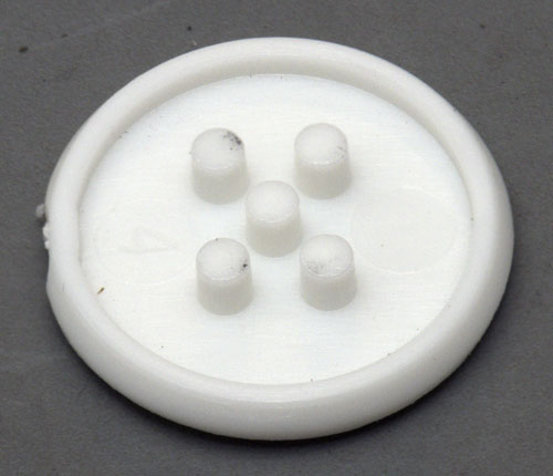
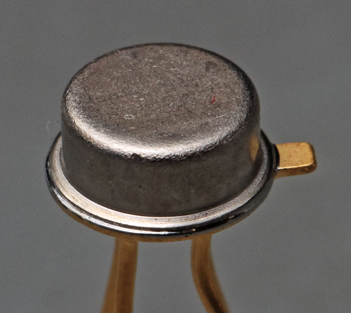


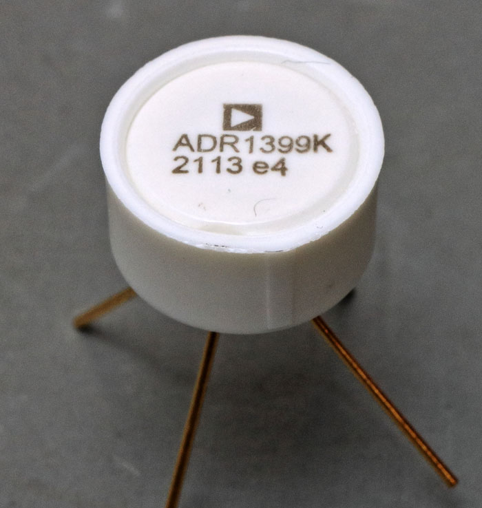
The package looks like the package of the LM399.
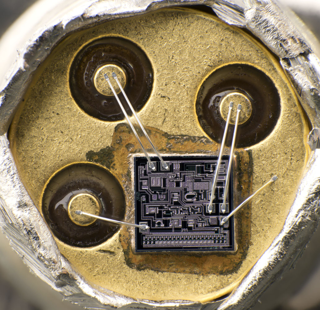


The package and the die look quite similar to the LM399 but there are two bondwires for the shunt regulator.
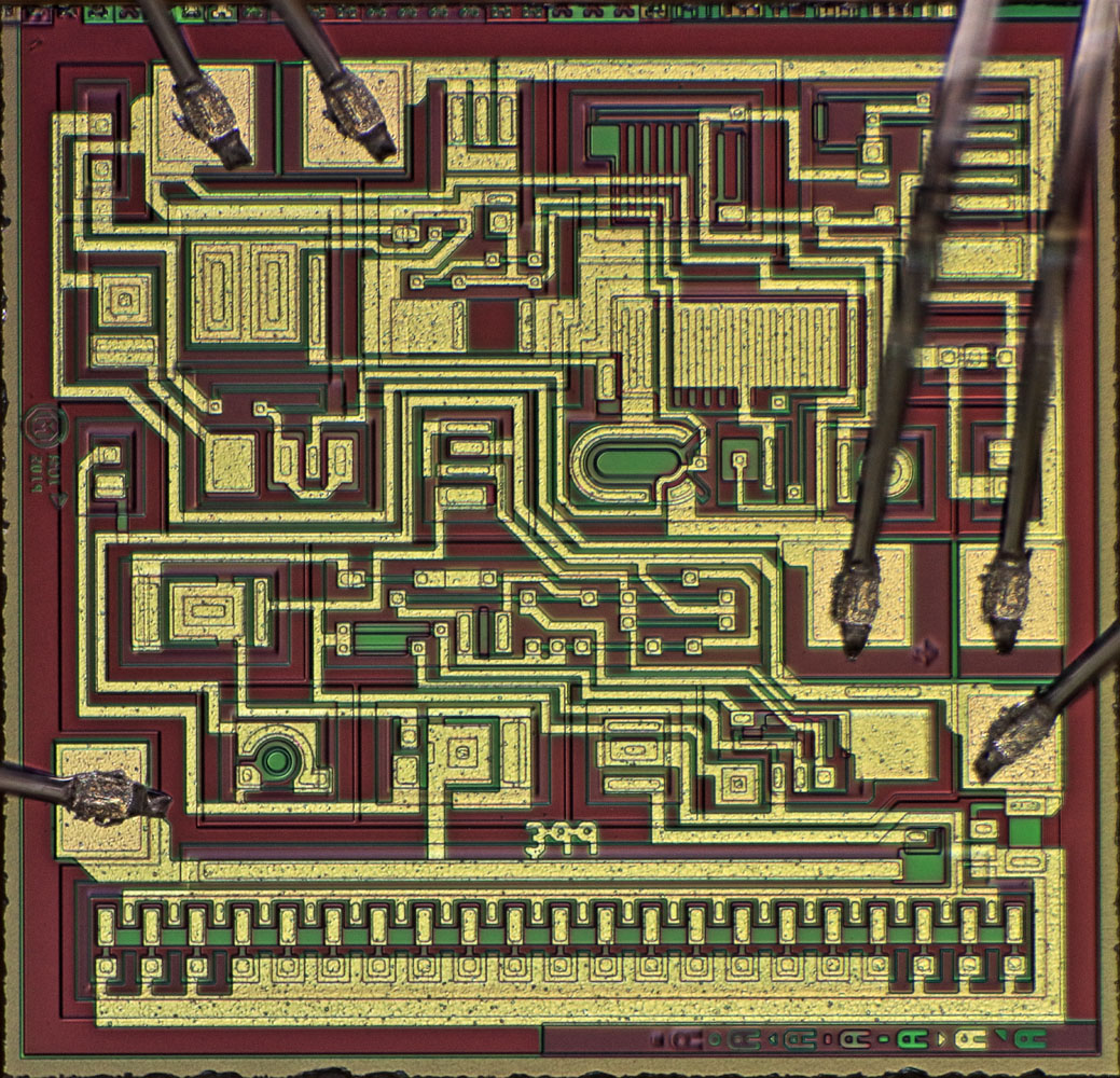
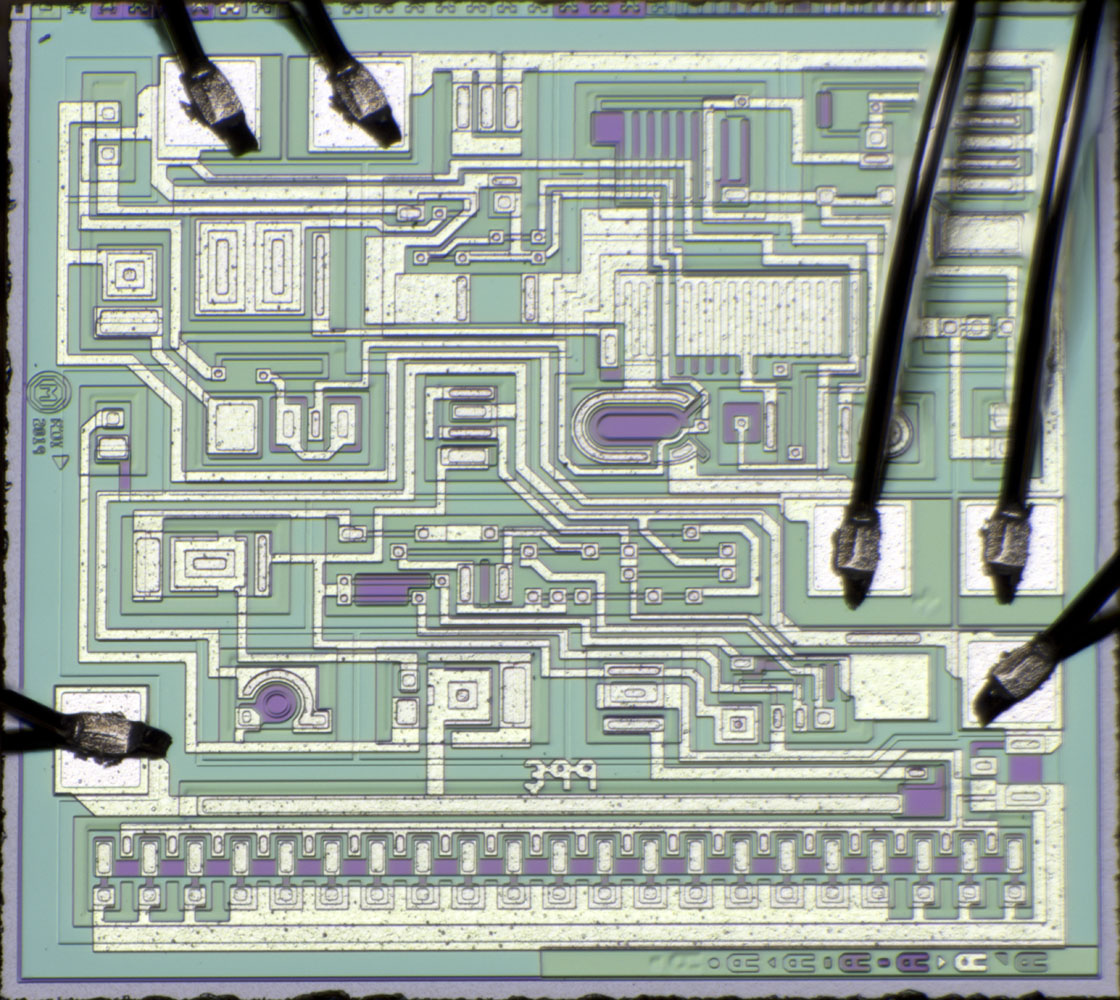


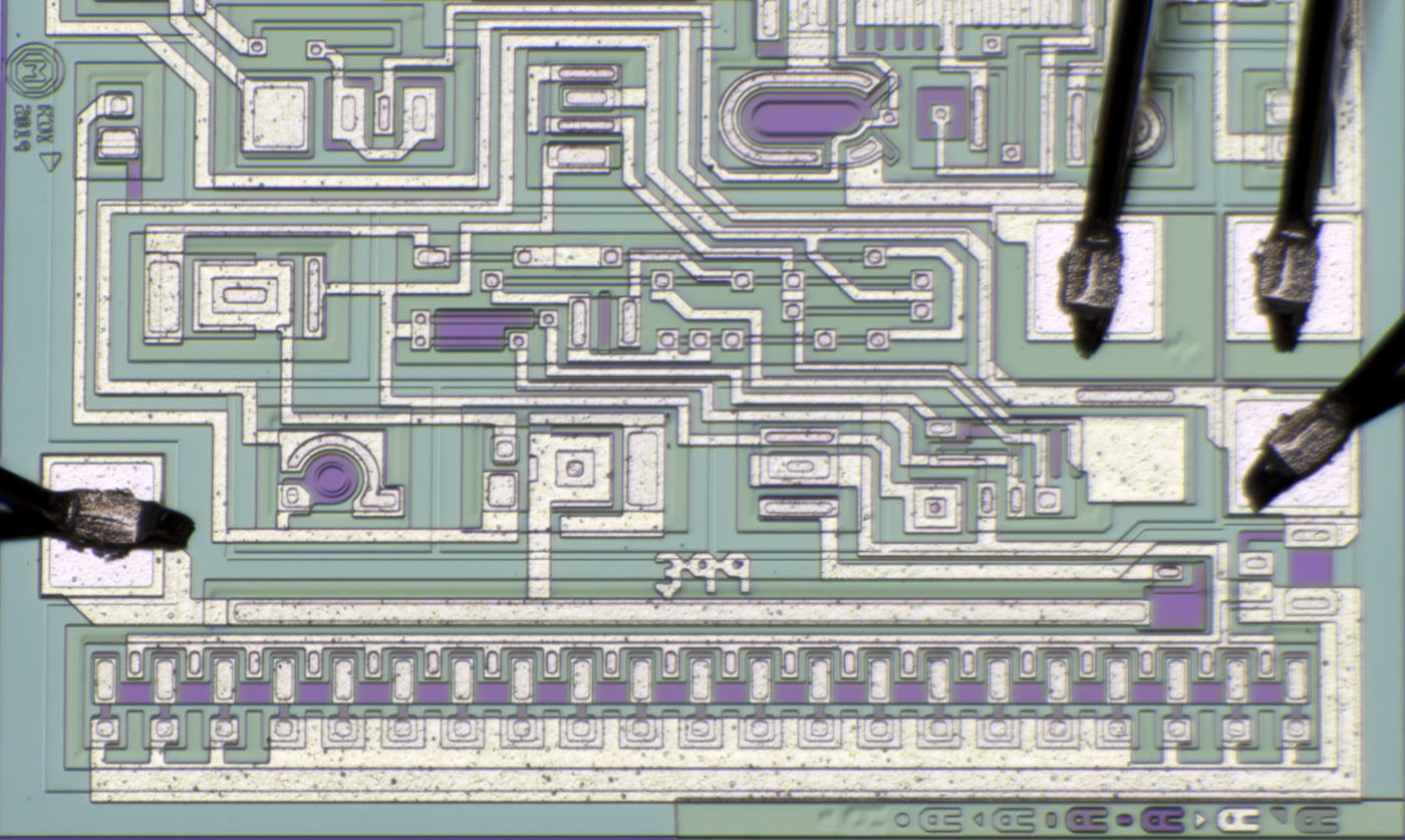
The die looks quite similar to the LM399 but there are some differences. It seems like Analog Devices integrated some new functions while trying to leave the structures as similar as possible.
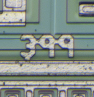
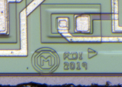


It´s a 399 designed by Analog Devices in 2019.


Seven masks like in the LM399. In the ADR1399 all of them are at the lower edge.
(Have you recognized the different symbols left of the letters? Nice...  8))


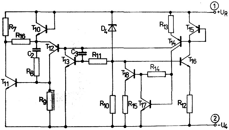
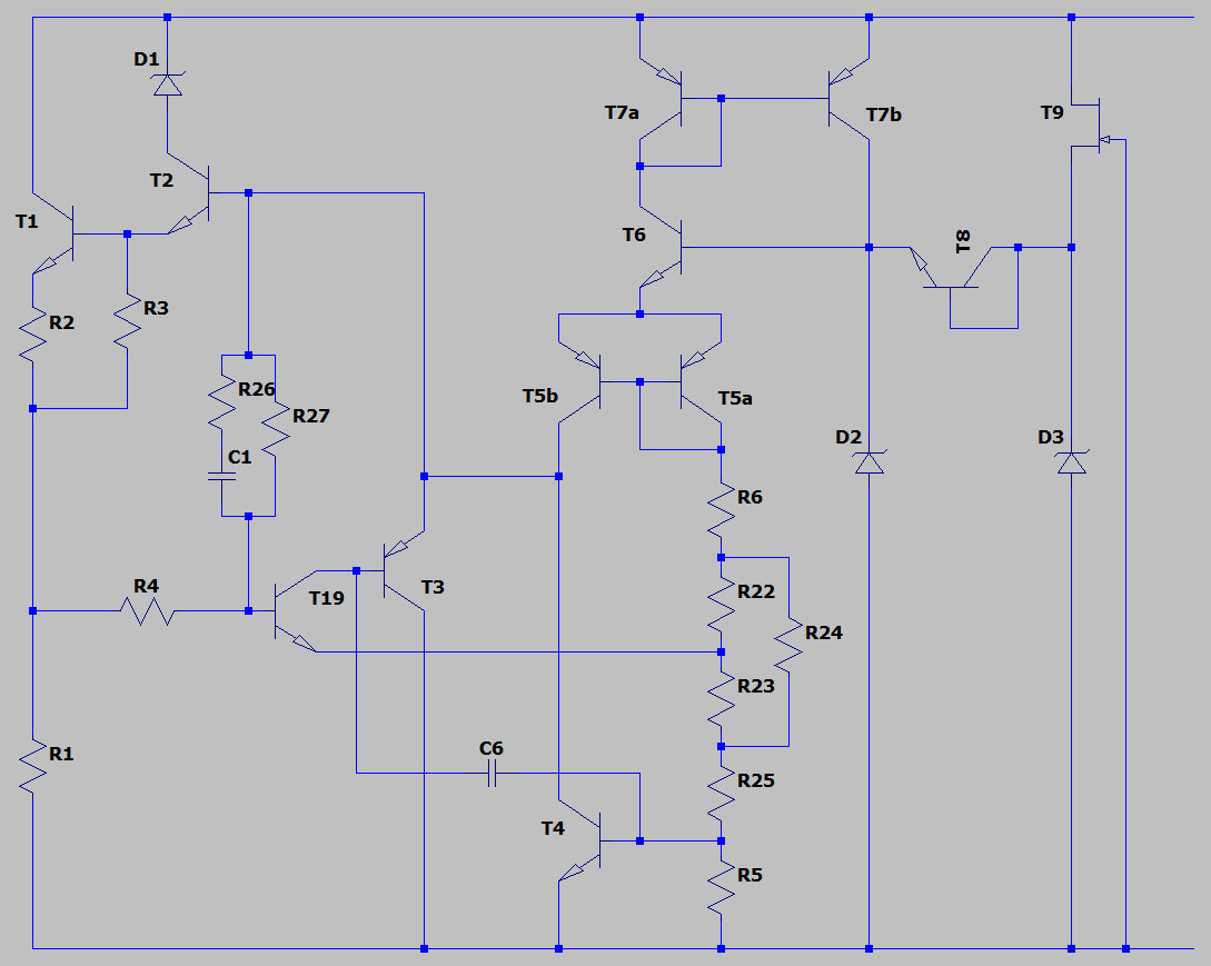
Let´s compare the ADR1399 with the schematic of the MAC199 which shows the LM399 circuit quite accurate.
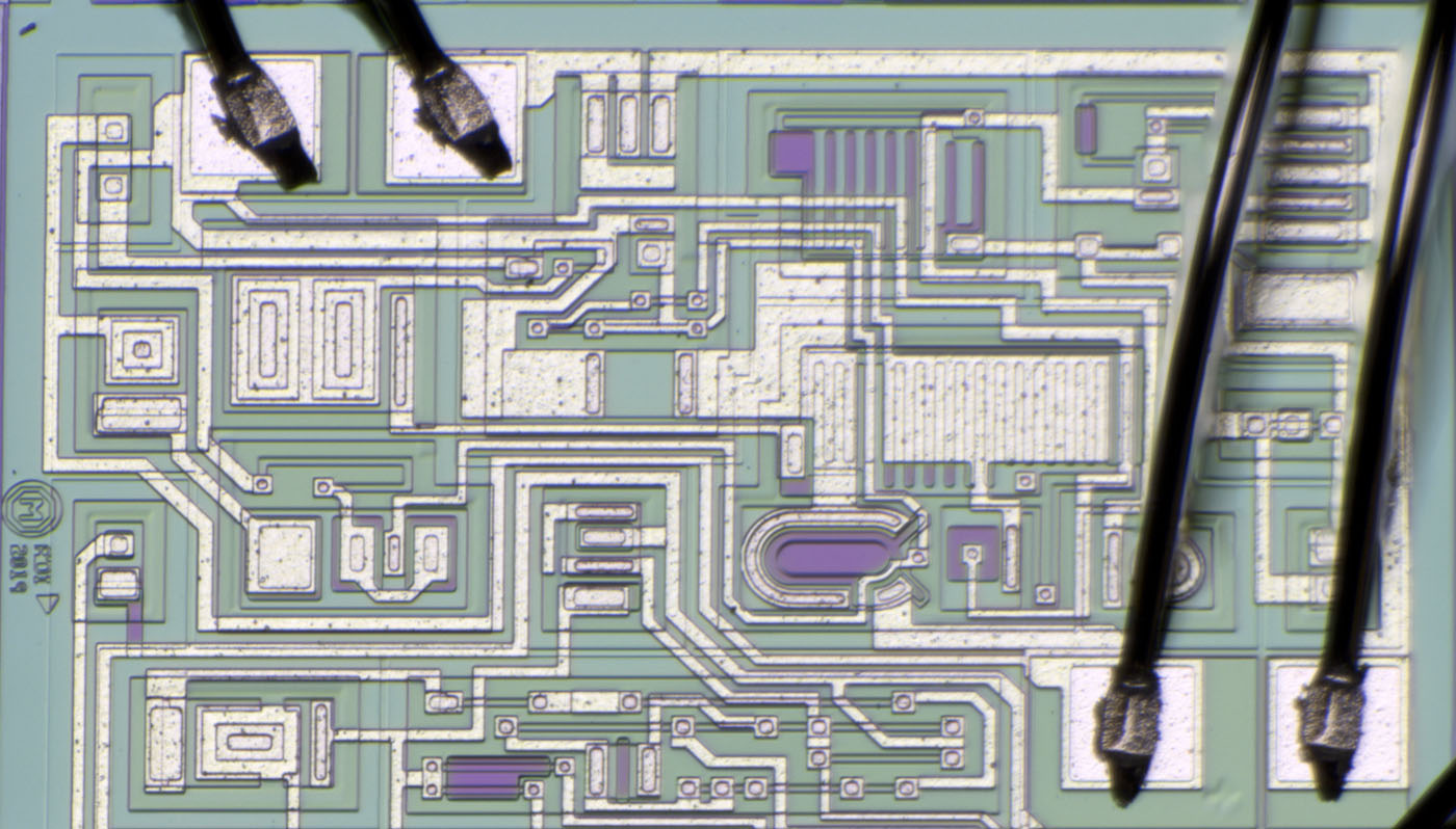
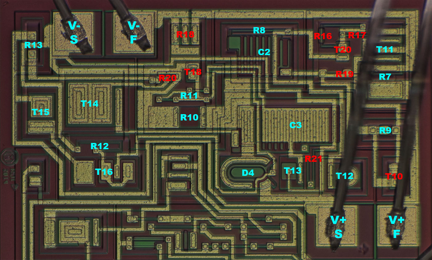


There are a lot of circuit parts that look like LM399 but some of them are wired differently and some parts were added (red).
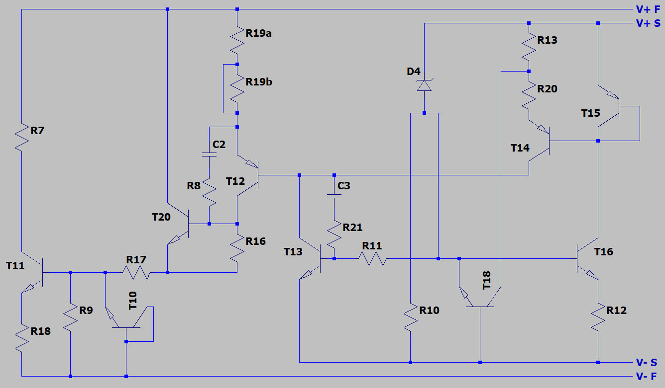


The circuit looks like this. The ADR1399 die allows Kelvin connection. There are two bondpads for the reference and control circuit and there are two bondpads for the power stage.

The zener D4 has an additional contact which makes it possible to connect the reference potential offside the bias current.

The control circuit T13/T16/T15/T14 is similar to the LM399 but here we have no additional current sink.

T18 seems to limit overvoltages that otherwise would cause current spikes that probably would damage the zener. The collector of T18 seems to be connected to R13/R20 coincidentaly. The collector base breakdown voltage is probably too high to be usefull. I assume R20 had just the right position to use its potential for the well of T18.

The output stage got an additional Transistor (T16), now it´s a Sziklai-Darlington-Stage. You probably need the higher current gain for the lower impedance of the shunt regulator.

The overcurrent protection was changed too. T10 drains base current of T11 if the voltage across R18 gets to high.
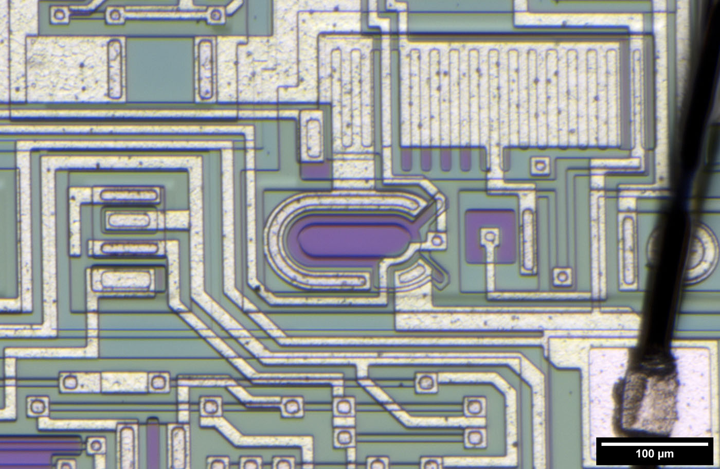


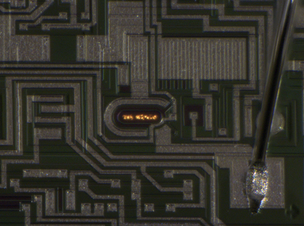
The buried zener is oval. It looks similar to the zeners of the LTFLU (https://www.richis-lab.de/REF04.htm).


And it glows in the dark...  ;D

Due to avalanche breakdown fast electrons lift electrons of the atoms on different higher stages. While falling back into their home position they emit different wavelengths.

The glow is located in the middle of the zener a little under the surface.
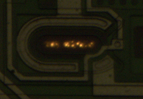


1mA
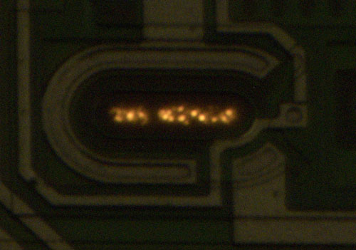


10mA

You can see the individual areas where the breakdown occurs. In the LTZ1000 we saw individual areas too (https://www.richis-lab.de/REF03.htm). In the ADR1000 the glow was a little more uniform (https://www.richis-lab.de/REF19.htm).  :-//


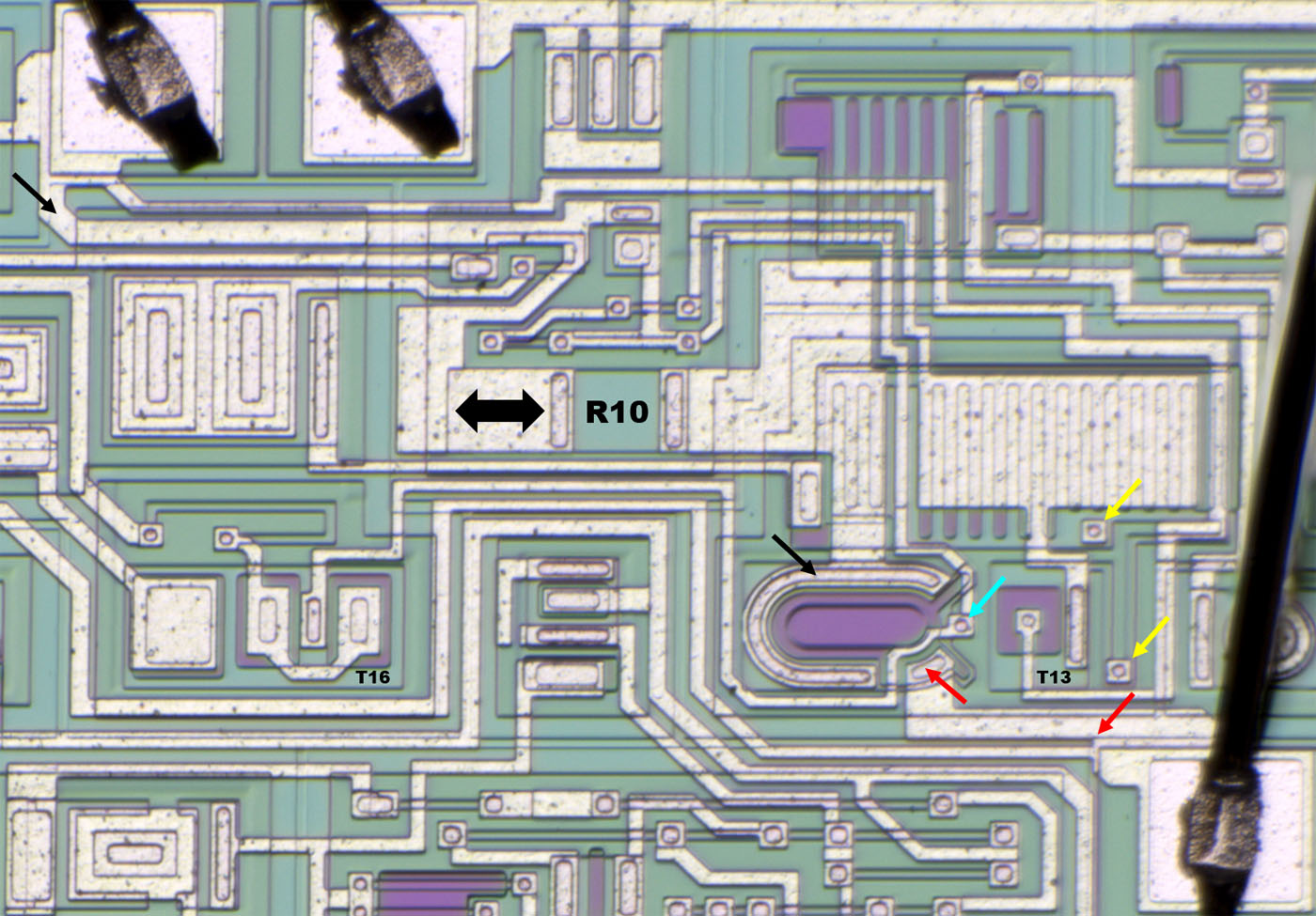
Here you can see the contact to the upper n-doped area (red). The contact for the bias current (black) and the additional contact for the reference voltage (cyan). It seems like the two "fingers" do some shielding against the additional contact.  :-//

R10 is low resistance probably because there is no additional current sink. One contact can be varied for different bias currents.

We have talked about the strange transistors. Magic has told us about tuning them for best performance of the reference. Here we see different but still strange transistors: T16 (left) contains two very big emitter areas. The T13 emitter area is very big too.

On the right side there are two contacts two lower the base resistance of T13 (yellow).
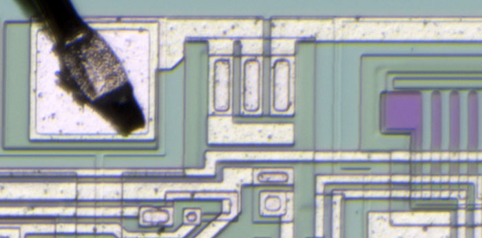


The resistor of the current limit circuit can be tuned a little.
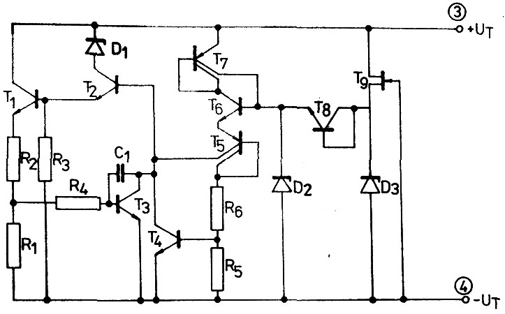


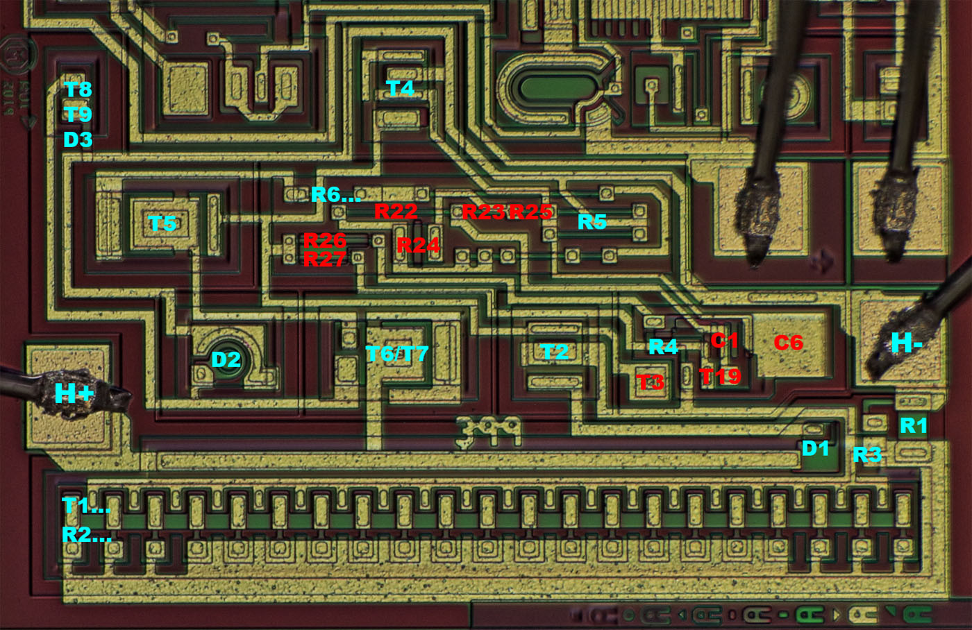
Now let´s take a look at the heater.


The reference circuit is the same as in the LM399. Just the voltage divider is more complex (R6, R22, R23, R24, R25, R5). T4, the temperature sensing transistor, is equipped with a second base contact. With the voltage divider resistors and the second base contact you can tune the working temperature of the ADR1399.

The heater stage is the same as in the LM399 but the current limiter looks different. T19 is sensing the current through R1 and drives T3. Furthermore T19 sources its emitter current into the voltage divider of T4.

This circuit made it possible to accelerate the heater. At an cold start-up the heater works in current limit mode. T19 drives T3 which sinks current from T1/T2 to limit the current. Emitter current from T19 makes T4 sinking current too. Collector current of T4 increases with temperature. At some point T4 drains enough current to drive T1/T2 out of current limit area. As a consequence T19 sources less current into the voltage divider and T4 sinks a little less current slowing down the decrease in heater current or in other words holding a high heater current for a longer time.

C6 and R26/C1/R27 were probably necessary to prevent oscillations.
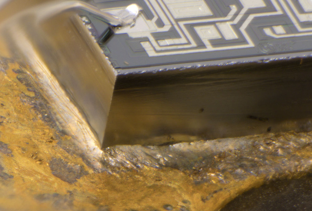


The ADR1399 has been sawn out of the wafer quite nicely while the last bit of the LM399 was broken.


https://www.richis-lab.de/REF20.htm

 :-/O

Offline NaxFM

  • Regular Contributor
  • *
  • Posts: 124
  • Country: it
Re: LM399/ADR1399
« Reply #53 on: January 21, 2022, 08:34:00 pm »
Wow, thank you for this breakdown!

The 399 label in the die is very curious, makes me think that maybe they just wanted to create un updated version of the 399 but the characteristic were not really 100% compatible with existing designs and maybe decided to create a new part instead?
Of course with the oscillation problem they could have never sold it as a regular 399
« Last Edit: January 21, 2022, 10:18:24 pm by NaxFM »
 

Offline Noopy

  • Super Contributor
  • ***
  • Posts: 1735
  • Country: de
    • Richis-Lab
Re: LM399/ADR1399
« Reply #54 on: January 21, 2022, 08:40:22 pm »
 :-+

It seems that Analog wanted or had to change some parts but at the same time they tried to leave as much of the old circuit as possible.

Offline Kleinstein

  • Super Contributor
  • ***
  • Posts: 14210
  • Country: de
Re: LM399/ADR1399
« Reply #55 on: January 21, 2022, 09:46:58 pm »
Wow, thank you for this breakdown!

The 399 label in the die is very curious, makes me think that maybe they just wanted to create un updated version of the 399 but the characteristic were not really 100% compatible with existing designs and decided to create a new part instead?
Of course with the oscillation problem they could have never sold it as a regular 399
A slight update with more current to the zener and thus less noise is definitely a good idea. AFAIK there was a similar part with a higher zener current and 10 V output (LM369).
 

Online magic

  • Super Contributor
  • ***
  • Posts: 6779
  • Country: pl
Re: LM399/ADR1399
« Reply #56 on: January 21, 2022, 10:28:00 pm »
What's this?
(This is the part that the commies omitted, which made you think that they disconnected the PNP mirror from T16.)


I'm not sure if T10 and R9 aren't connected to T12 emitter rather than ground. But I have no answer to the question where is the resistor bypassing T11 BE junction in such case.

And I disapprove of your choice of graphics format for schematic drawings ;)
 

Offline Noopy

  • Super Contributor
  • ***
  • Posts: 1735
  • Country: de
    • Richis-Lab
Re: LM399/ADR1399
« Reply #57 on: January 22, 2022, 04:33:20 am »
What's this?
(This is the part that the commies omitted, which made you think that they disconnected the PNP mirror from T16.)


You talk about the LM399, aren´t you?
Well you can´t be sure if the second "collector connection" is a window in the base area (collector connection) or a emitter area (second emitter).
Of course a emitter would make more sense but it makes no sense to connect it to the collector!?


I'm not sure if T10 and R9 aren't connected to T12 emitter rather than ground. But I have no answer to the question where is the resistor bypassing T11 BE junction in such case.


I have a better picture for you.  :-+


And I disapprove of your choice of graphics format for schematic drawings ;)

Probably you are right...  ;D
 
The following users thanked this post: magic

Online magic

  • Super Contributor
  • ***
  • Posts: 6779
  • Country: pl
Re: LM399/ADR1399
« Reply #58 on: January 22, 2022, 09:33:24 am »
I have a better picture for you.  :-+
That's better :D

I'm talking about both LM399 and ADR1399. It definitely looks like an emitter to me.
It can't be a base connection (the circuit wouldn't work at all).
It's unlikely to be collector (a few collector connections marked in red for reference, look different to me).
There would be no point surrounding a collector connection with a base diffusion.

So what is this reverse biased emitter doing? :-//
 

Offline Noopy

  • Super Contributor
  • ***
  • Posts: 1735
  • Country: de
    • Richis-Lab
Re: LM399/ADR1399
« Reply #59 on: January 22, 2022, 04:15:15 pm »
Now I see your point!

My first guess was that there is a hole in the base area making it possible to connect the collector. Of course that would be a strange construction but connecting a spare emitter to the collector is strange too.  :-//
If it's a emitter it would act like a zener hopefully with a higher breakdown voltage than D4 - Vbe of T15. But then it would do nothing...

Perhaps that is something like the circuit you found in the Zeptobars-723: It doesn't make sense but it doesn't cause problems either. Perhaps there is a designer laughing about people like us thinking about this connection.  ;D

Offline Noopy

  • Super Contributor
  • ***
  • Posts: 1735
  • Country: de
    • Richis-Lab
Re: LM399/ADR1399
« Reply #60 on: January 24, 2022, 06:48:58 pm »


I have stripped the passivation and the metal layer.
=> Yes, it looks like the leftmost contact of T16 is another emitter.  :-+

https://www.richis-lab.de/REF20.htm#Update
 
The following users thanked this post: Andreas, antintedo

Online Andreas

  • Super Contributor
  • ***
  • Posts: 3248
  • Country: de
Re: LM399/ADR1399
« Reply #61 on: January 26, 2022, 07:22:12 pm »
Hello,

perhaps interesting for those in DE or in EU: Availability status of ADR1399KH has changed from "0 stock" to some parts available end of February on Mouser.de

with best regards

Andreas
 

Offline Noopy

  • Super Contributor
  • ***
  • Posts: 1735
  • Country: de
    • Richis-Lab
Re: LM399/ADR1399
« Reply #62 on: February 04, 2022, 08:51:56 pm »
What's this?
(This is the part that the commies omitted, which made you think that they disconnected the PNP mirror from T16.)


I have a new theory about this structure. Perhaps that´s a lateral NPN in parallel to the vertical NPN. The left emitter could act as second collector.
I´m not sure why one should do this but it would explain why they connected a "emitter" of T16 to T15.


Share me

Digg  Facebook  SlashDot  Delicious  Technorati  Twitter  Google  Yahoo
Smf