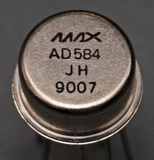
Author Topic: More voltage references - die pictures  (Read 42661 times)

0 Members and 1 Guest are viewing this topic.

Offline NoopyTopic starter

  • Super Contributor
  • ***
  • Posts: 1726
  • Country: de
    • Richis-Lab
More voltage references - die pictures
« on: April 12, 2020, 05:59:20 pm »

Hi all!


I don´t want to blow the metrology section apart, so I will post less important references in this topic.


Today I have a LT1009 for you:


I have also done some reverse engineering.

It seems that they can change the reference voltage by changing the metal layer. Most parts of the 6k6-resistors are shorted here.

In the upper right corner there are some parts that are not connected. Perhaps a spare function? A start-up-circuit? It seems that this circuit has also a fusible link.

And I found a small hidden capacitor looking like an F. At least I think it´s a capacitor.

See more at my website:

https://www.richis-lab.de/REF10.htm

 :popcorn:

Offline NoopyTopic starter

  • Super Contributor
  • ***
  • Posts: 1726
  • Country: de
    • Richis-Lab
Re: More voltage references - die pictures
« Reply #1 on: April 28, 2020, 08:31:38 pm »

Today I have a LT1029 for you:

https://richis-lab.de/REF11.htm


The specifications are quite simliar to the LT1009 but the die is much more complex. It seems that it´s based on the LT1019 design because you can read 1019B on the die.


The die could be kelvin connected. The two bondpads placed at the ground potential and the two placed at the v+ potential are isolated from eacht other so you can compensate the bondwire resistance even without kelvin connection outside the package. That seems more intelligent than in the LT1236 where the kelvin connection pads are connected on the die.


A nice bandgap configuration!


You can compensate the temperature drift with the fusible resistors in the bottom left corner that belong to the bandgap circuit. Fusing the resistors in the upper right courner you can adjust the output voltage because they are placed in the feedback path.


 :popcorn:

 
The following users thanked this post: Andreas, doktor pyta, laneboysrc, The Soulman, ramon, Simon_RL

Online Andreas

  • Super Contributor
  • ***
  • Posts: 3238
  • Country: de
Re: More voltage references - die pictures
« Reply #2 on: April 29, 2020, 06:06:55 pm »
Hmm,

the LT1019 has a heater pin and a heater resistor (hidden in the newer datasheets).

https://www.datasheetarchive.com/pdf/download.php?id=4628e6e0c37324eca3aefd62a37ec0b715ab84&type=P&term=LT1019-5

the problem is that there is no extra ground pin and the heater current shifts the output voltage due to common impedance effects.

But if its the same die the heater structure should be somewhere visible

With best regards

Andreas
 

Offline NoopyTopic starter

  • Super Contributor
  • ***
  • Posts: 1726
  • Country: de
    • Richis-Lab
Re: More voltage references - die pictures
« Reply #3 on: May 01, 2020, 07:18:32 am »

Where did you find a heater in the datasheet?  :-//

Well I think I will have to decap a LT1019...  ;D

Best Regards,

Richard

Online Andreas

  • Super Contributor
  • ***
  • Posts: 3238
  • Country: de
Re: More voltage references - die pictures
« Reply #4 on: May 01, 2020, 08:18:32 am »
In the above linked datasheet (old version Rev B) page 2 + page 3 (see PIN 7)

see also AN42 page 15
https://www.analog.com/media/en/technical-documentation/application-notes/an42.pdf

with best regards

Andreas
 
The following users thanked this post: Noopy

Offline NoopyTopic starter

  • Super Contributor
  • ***
  • Posts: 1726
  • Country: de
    • Richis-Lab
Re: More voltage references - die pictures
« Reply #5 on: May 01, 2020, 08:25:44 am »
Sorry, I was somehow blind. I need more coffee...  ;D
You are absolutely right.
Perhaps the heater is not on the same die? Although that would not be very reasonable...

I have to decap a LT1019!  :-/O
 
The following users thanked this post: Andreas

Offline NoopyTopic starter

  • Super Contributor
  • ***
  • Posts: 1726
  • Country: de
    • Richis-Lab
Re: More voltage references - die pictures
« Reply #6 on: July 20, 2020, 08:43:05 pm »

I have some new die pictures for you.
I have taken a closer look at a AD588 (revision A).
That´s a quite interesting reference. Two outputs, bipolar, bipolar floating, Kelvin Connection...  8)


The AD588 uses two metal layers as the AD587 does (https://www.richis-lab.de/REF06.htm).


It´s quite easy to identify the big blocks (reference, opamps A1, A2, A3, A4).


Analog used an interesting resistor to tune the reference (I assume the temperature coefficient). They used a "normal" laser trimmed resistor and connected it in series with a "big, splitted resistor" in which they cutted whole resistors.


The AD588 uses the "Analog-buried-Zener" you can also find in the AD587 (https://www.richis-lab.de/REF06.htm) and in in the AD565 (https://www.richis-lab.de/DAC06.htm).


You can find a buried zener in every opamp!  :wtf:


More pictures here:

https://www.richis-lab.de/REF12.htm

 :popcorn:
 
The following users thanked this post: lowimpedance, chickenHeadKnob, Andreas, exe, Gyro

Online magic

  • Super Contributor
  • ***
  • Posts: 6749
  • Country: pl
Re: More voltage references - die pictures
« Reply #7 on: July 21, 2020, 07:22:59 am »
That looks similar to the 587. The opamps use µA741 input stages again. The zeners are probably for local bias generation in each opamp - they don't seem to have any connection to the primary reference cell to derive their bias from it.
 

Offline NoopyTopic starter

  • Super Contributor
  • ***
  • Posts: 1726
  • Country: de
    • Richis-Lab
Re: More voltage references - die pictures
« Reply #8 on: July 21, 2020, 08:55:05 am »
That looks similar to the 587. The opamps use µA741 input stages again. The zeners are probably for local bias generation in each opamp - they don't seem to have any connection to the primary reference cell to derive their bias from it.

 :-+

Nevertheless it´s interesting they used buried zeners for the bias generation.  :-/O

Online magic

  • Super Contributor
  • ***
  • Posts: 6749
  • Country: pl
Re: More voltage references - die pictures
« Reply #9 on: July 21, 2020, 09:59:57 am »


Analog used an interesting resistor to tune the reference (I assume the temperature coefficient). They used a "normal" laser trimmed resistor and connected it in series with a "big, splitted resistor" in which they cutted whole resistors.
Yes, that's tempco trim. The reference circuit is about the same as AD587 and this is the R1/R2 divider. Q1-Q3 are the big NPNs near the zener and they used a quad PNP Wilson mirror this time for Q1 base current cancellation (visible above). Ground connections from the reference cell seem to use Kelvin routing to the output stage of A2. I wonder how thermal gradients from A2 affect performance, given that those three NPNs are supposed to compensate each other in various ways and that the input stage of A1 also is laid out along the gradient. Possibly not a good idea to load Vlow.
 
The following users thanked this post: alm, Noopy

Offline NoopyTopic starter

  • Super Contributor
  • ***
  • Posts: 1726
  • Country: de
    • Richis-Lab
Re: More voltage references - die pictures
« Reply #10 on: July 21, 2020, 10:34:21 am »
...

It´s always a pleassure to read your explanations.  :-+ :popcorn:

Offline NoopyTopic starter

  • Super Contributor
  • ***
  • Posts: 1726
  • Country: de
    • Richis-Lab
Re: More voltage references - die pictures
« Reply #11 on: July 21, 2020, 06:48:29 pm »
I decapped some more AD588 (three).
Someone bought a batch AD588 over eBay. He said some didn´t work as they should. The first AD588 was a good one, the following AD588 is one of the buggy parts.
They all (the good and the bad) had the same package marking engraved in the metal lid.


What´s that? A newer revision. It is called C588. The C pretty sure stands vor revision C. It was designed 1987 (revision A was designed 1985).
They changed a lot on the die it´s not just a die shrink or some minor modifications. Nevertheless they didn´t change the lid marking.
Furthermore it seems that in 2005 they still used an old revision (A, 1985)! Perhaps they had a big stock pile of the old revision. Perhaps they had problems with the newer revision and had to go back to the old revision but still had a big stock pile of the new revision.  :-//
Strange things happen...


- They moved the zener and the transistors away from the output stage of A2 and arranged the transistors around the zener.

[...]
I wonder how thermal gradients from A2 affect performance, given that those three NPNs are supposed to compensate each other in various ways and that the input stage of A1 also is laid out along the gradient. Possibly not a good idea to load Vlow.
[...]

 :-+ :popcorn: :)

- They integrated an additional buried zener. It seems that the zener is used to supply some bias generator.
- They moved the capacitor in the bottom left corner of revision A upwards and integrated one more capacitor.
- There are unused transistors in the upper left corner. These transistors didn´t exist in revision A. I assume there was a revision B in which these transistors had been integrated in the reference block.


The opamp A2 is quite similar to the revision A but there is some more circuit at GND-SENSE+. It seems that this circuit adjusts the bias in the differential input stage in relation to the common mode voltage at the input.


The opamps A3 and A4 have some additional parts at the output stage. It seems like they integrated some protection circuits here.


More pictures here:
https://www.richis-lab.de/REF13.htm
Overview over all decapped references:
https://www.richis-lab.de/REF00.htm

 :popcorn:
« Last Edit: July 21, 2020, 07:46:45 pm by Noopy »
 

Online Andreas

  • Super Contributor
  • ***
  • Posts: 3238
  • Country: de
Re: More voltage references - die pictures
« Reply #12 on: July 21, 2020, 08:24:19 pm »

What´s that? A newer revision. It is called C588. The C pretty sure stands vor revision C. It was designed 1987 (revision A was designed 1985).
They changed a lot on the die it´s not just a die shrink or some minor modifications. Nevertheless they didn´t change the lid marking.
Furthermore it seems that in 2005 they still used an old revision (A, 1985)!

Hello,

from the picture above the lid looks sanded. (no original manufacturer would do this).
So I guess that those EBAY parts are pulled and remarked parts.
I would not make much guesses about the manufacturing in this case.

In 1992 Databook the side brazed DIP (D) package is still listed.
https://archive.org/details/bitsavers_analogDevilogDevicesDataConverterReferenceManualVo_129751587/page/n1251/mode/2up

In 1996 Databook only the CERDIP (Q) package is still available.
https://archive.org/details/bitsavers_analogDevilogDevicesDesignersReferenceManual_112939486/page/n687/mode/2up

So for me a side brazed dip in 2005 smells like counterfeit.

With best regards

Andreas
 
The following users thanked this post: Noopy

Offline NoopyTopic starter

  • Super Contributor
  • ***
  • Posts: 1726
  • Country: de
    • Richis-Lab
Re: More voltage references - die pictures
« Reply #13 on: July 21, 2020, 08:42:18 pm »
Hello Andreas,

probably you are right. That sounds more plausible too.
I could not believe that this metal lid got a new marking. The writing looked so nice...

Best regards,

Richard

Online magic

  • Super Contributor
  • ***
  • Posts: 6749
  • Country: pl
Re: More voltage references - die pictures
« Reply #14 on: July 21, 2020, 08:50:44 pm »
Just wanted to say the same :)

And I think you swapped GND SENSE + and -. Your order doesn't match the pinout.

The new circuit in A2 is input bias cancellation, I think. It makes sense, because the inverting input of this amplifier can see high impedance in the ±5V configuration, which is not matched by an equal impedance on the noninverting input. Its bias current could potentially disturb the 50:50 divider too, maybe.

It seems that the whole current of the input stage and the current sink which biases the input stage (4x the current of one input transistor) goes through an NPN identical to the input ones and the base current of that NPN is mirrored at 25% ratio into a common base PNP (not sure what that one is doing) and from there goes to the input pin.

This offers simple means of determining the die revision nondestructively.

You also missed another tweak, which is found in the 1987 AD587 too: the connections between the input stage NPNs and PNPs are crossed over. This presumably offers some thermal gradient cancellation - if there is a vertical gradient, the NPN of one branch and the PNP of the other branch get hotter, and offset voltage of both branches shifts about equally.
« Last Edit: July 21, 2020, 09:20:57 pm by magic »
 
The following users thanked this post: Noopy

Online Andreas

  • Super Contributor
  • ***
  • Posts: 3238
  • Country: de
Re: More voltage references - die pictures
« Reply #15 on: July 21, 2020, 09:17:12 pm »
The writing looked so nice...
Hello Richard,

from the first look: yes
So if there were no different chip revisions in the same date code I would not have been sceptical.

In worst case you can remove the markings with acetone.

https://www.eevblog.com/forum/metrology/ad587lq-from-aliexpress/msg2023066/#msg2023066

with best regards

Andreas
 

Online mawyatt

  • Super Contributor
  • ***
  • Posts: 3234
  • Country: us
Re: More voltage references - die pictures
« Reply #16 on: July 22, 2020, 02:12:57 am »


You also missed another tweak, which is found in the 1987 AD587 too: the connections between the input stage NPNs and PNPs are crossed over. This presumably offers some thermal gradient cancellation - if there is a vertical gradient, the NPN of one branch and the PNP of the other branch get hotter, and offset voltage of both branches shifts about equally.

This is a cross-coupled quad type arrangement, common with precision differential stages. Originally developed by George Erdi long ago at Fairchild and utilized in the 1st precision op-amp the ua725 I believe.

It not only helps with thermal gradients, but also process gradients.

Best,
Curiosity killed the cat, also depleted my wallet!
~Wyatt Labs by Mike~
 

Offline NoopyTopic starter

  • Super Contributor
  • ***
  • Posts: 1726
  • Country: de
    • Richis-Lab
Re: More voltage references - die pictures
« Reply #17 on: July 22, 2020, 02:53:19 am »
Thanks for all your input! I will add that to my website soon.  :-+


The writing looked so nice...
Hello Richard,

from the first look: yes
So if there were no different chip revisions in the same date code I would not have been sceptical.

In worst case you can remove the markings with acetone.

https://www.eevblog.com/forum/metrology/ad587lq-from-aliexpress/msg2023066/#msg2023066

with best regards

Andreas

That was the point that puzzled me: That´s no cheap print on the AD588 lid there are nice deep laser drillings.
If the original marking was made with the same technique you have to sand a lot to get rid of it.  :-/O
« Last Edit: July 22, 2020, 03:06:06 am by Noopy »
 

Online magic

  • Super Contributor
  • ***
  • Posts: 6749
  • Country: pl
Re: More voltage references - die pictures
« Reply #18 on: July 22, 2020, 03:18:36 am »
This is a cross-coupled quad type arrangement, common with precision differential stages. Originally developed by George Erdi long ago at Fairchild and utilized in the 1st precision op-amp the ua725 I believe.

It not only helps with thermal gradients, but also process gradients.
Yes indeed. Kinda, sorta.
The precision opamp input stages use four identical transistors. This one is a mix of NPNs and PNPs.
I'm not sure if it ends up cancelling much process gradients, given that they likely affect the two types differently.
The primary goal here is stability, not ultimate precision, or they wouldn't be using the 741 topology.
 

Offline NoopyTopic starter

  • Super Contributor
  • ***
  • Posts: 1726
  • Country: de
    • Richis-Lab
Re: More voltage references - die pictures
« Reply #19 on: August 24, 2020, 09:03:07 pm »
Today I have a MAX6325 for you:


The die is HUGE: 3,74mm x 2,19mm in a SO8-package!  :o

Unfortunatelly the picture quality is not as good as I would have wished it to be. (Is that really english or more german?  ;D)


The design was built by Maxim in 1997.


I assume that´s the +/-15mA-Push-Pull-output-stage.
It´s quite big for +/-15mA but it has to be good enough for a voltage reference.
It seems that the lowsider has it´s one ground pad. Would be reasonable.


Maxim left "a lot" of room between the components.
Unfortunatelly I didn´t find the buried zener. The structures are to small...  :'(


Some testpads...
Not very important but interesting: The connections to the capacitors at the bottom are quite different. Hey that are capacitors the connections are quite irrelevant.  :-//


https://www.richis-lab.de/REF14.htm


 :popcorn:
 
The following users thanked this post: Andreas, l3VGV, serg-el

Offline razvan784

  • Regular Contributor
  • *
  • Posts: 90
  • Country: ro
Re: More voltage references - die pictures
« Reply #20 on: August 24, 2020, 09:41:59 pm »
W...T...F... :o that looks more like a standard cell ASIC than a precision voltage reference...
Digital trim / temperature compensation? Many features look analog though...
One can wonder how all these complications effect long-term drift...
« Last Edit: August 24, 2020, 09:46:55 pm by razvan784 »
 

Offline NoopyTopic starter

  • Super Contributor
  • ***
  • Posts: 1726
  • Country: de
    • Richis-Lab
Re: More voltage references - die pictures
« Reply #21 on: August 24, 2020, 09:51:51 pm »
Quite strange...

But I don´t see any digital circuit. I assume Maxim integrated a lot of analog circuits to compensate whatever...

If you want to check my pictures in detail:

https://www.richis-lab.de/temp/01.jpg
https://www.richis-lab.de/temp/02.jpg

Offline T3sl4co1l

  • Super Contributor
  • ***
  • Posts: 21651
  • Country: us
  • Expert, Analog Electronics, PCB Layout, EMC
    • Seven Transistor Labs
Re: More voltage references - die pictures
« Reply #22 on: August 25, 2020, 03:30:12 am »
Y'don't suppose G-T, E-E, O-G are the designers..?

Sure seems like there's enough circuitry in there to measure temperature and compensate for it, perhaps digitally.  But even then, did they just... make 10 of everything and wire it in parallel, just because..?!

Tim
Seven Transistor Labs, LLC
Electronic design, from concept to prototype.
Bringing a project to life?  Send me a message!
 
The following users thanked this post: Noopy

Offline NoopyTopic starter

  • Super Contributor
  • ***
  • Posts: 1726
  • Country: de
    • Richis-Lab
Re: More voltage references - die pictures
« Reply #23 on: August 25, 2020, 03:37:44 am »
Y'don't suppose G-T, E-E, O-G are the designers..?


Aha! Sounds very reasonable!  :-+

Online magic

  • Super Contributor
  • ***
  • Posts: 6749
  • Country: pl
Re: More voltage references - die pictures
« Reply #24 on: August 25, 2020, 08:32:07 am »
A vast majority of this die looks like low density analog to me :-//
I think they may have a complementary process here given the additional diffusions surrounding some transistors, presumably PNPs. A wild guess as to what is what:


As can be deduced, I'm not exactly sure what WAT and WTF might be. Perhaps larger BJTs, or maybe MOS? Who knows, MAX6250 datasheet says it's fabbed on a CMOS process, maybe this one is BiCMOS. But MAX6350 datasheet also says 435 transistors and I have no idea where they are.

I agree with Noopy that the left side is probably the output stage. This means the bondig pads are, top-bottom and left-right:
output stage ground, precision ground, noise reduce, input voltage, do not connect
trim, output voltage, probably output sense, dnc, dnc

It seems to make sense. Ground, input and output are quite fat. Noise reduce appears to cross under a Vin trace and go to some circuitry in the top right corner. Trim is another thin trace which goes somewhere to the right.

edit
For instance, the pair of structures below the P in NPN appears to be a simple current mirror, with the top tranny being the input (B-C shorted). The one I labeled PNP also seems B-C shorted, but an identical transistor on the right is not. I'm pretty sure that the "zeners" are indeed zeners because they look similar to other zeners we have seen and what else could those things be with apparently only two terminals?
« Last Edit: August 25, 2020, 08:43:24 am by magic »
 

Online Mickle T.

  • Frequent Contributor
  • **
  • Posts: 467
  • Country: ru
Re: More voltage references - die pictures
« Reply #25 on: August 30, 2020, 05:46:38 pm »
Thaler VRE305K magic:

 
The following users thanked this post: Andreas, serg-el

Offline doktor pyta

  • Frequent Contributor
  • **
  • Posts: 488
  • Country: pl
Re: More voltage references - die pictures
« Reply #26 on: August 30, 2020, 08:21:19 pm »
We were missing You, Михаил :)

Offline NoopyTopic starter

  • Super Contributor
  • ***
  • Posts: 1726
  • Country: de
    • Richis-Lab
Re: More voltage references - die pictures
« Reply #27 on: January 27, 2021, 10:44:46 am »
We had no reference for a long time...  :'(


Let´s take a look into a SZY22, a reference built by the "Werk für Fernsehelektronik".
With a current of 5mA it generates a voltage of 8,4V +/-0,4V.


The tempco depends on the sorting:
SZY20: black dot: 100ppm/K
SZY21: yellow dot: 50ppm/K
SZY22: blue dot: 20ppm/K
SZY23: red dot: 10ppm/K


Datasheet states three diodes, one acting as zener and two acting as "normal" diodes. The diodes are chosen in a way that the positive tempco of the zener compensates the negative tempco of the "normal" diodes.


The diodes are potted in epoxy. In the epoxy you can spot a board carrying the diodes and a second board isolating the first board against the metal case.


400°C later => surprise: There are only two diodes.  :o
It seems WF has optimized the reference so the tempcos compensate each other with only two diodes.
On the diodes there is a sticky residue. Probably they were protected with a different substance.


After cleaning we find two glass diodes.


The diode is a n-doped silicon plate with a metal part alloyed onto it. I assume that is Al which gives a p-doping.


While decapping the tin got liquid. In the second diode the tin now is located in the active area but i looks like the second diode had a similar construction as the first one.


https://www.richis-lab.de/REF15.htm

 :-/O
 
The following users thanked this post: doktor pyta, RoGeorge, guenthert, iMo

Offline Gyro

  • Super Contributor
  • ***
  • Posts: 9473
  • Country: gb
Re: More voltage references - die pictures
« Reply #28 on: January 27, 2021, 11:03:25 am »
Datasheet states three diodes, one acting as zener and two acting as "normal" diodes. The diodes are chosen in a way that the positive tempco of the zener compensates the negative tempco of the "normal" diodes.

...

400°C later => surprise: There are only two diodes.  :o
It seems WF has optimized the reference so the tempcos compensate each other with only two diodes.
On the diodes there is a sticky residue. Probably they were protected with a different substance.

One of the diode packages is probably a temperature compensated reference zener - something like a 1N827-9 with an internal series compensating diode junction.
Best Regards, Chris
 

Offline NoopyTopic starter

  • Super Contributor
  • ***
  • Posts: 1726
  • Country: de
    • Richis-Lab
Re: More voltage references - die pictures
« Reply #29 on: January 27, 2021, 11:23:16 am »
One of the diode packages is probably a temperature compensated reference zener - something like a 1N827-9 with an internal series compensating diode junction.

But then you would not need a second diode. And both diodes look the same, you can't spot a special construction.

Update: Of course you would expect a second diode for 8,4V. => 8,4V zener usually needs two diodes for compensation of the tempco.
But nevertheless you can´t spot a special construction of the diodes.
And as I wrote later perhaps WF was able to compensate the tempcos with only one zener and one "normal" diode.
« Last Edit: January 27, 2021, 01:49:23 pm by Noopy »
 

Online iMo

  • Super Contributor
  • ***
  • Posts: 4749
  • Country: nr
  • It's important to try new things..
Re: More voltage references - die pictures
« Reply #30 on: January 27, 2021, 11:45:44 am »
FYI - attached a 1997 pdf how the 1N829 diodes were made..
I have got here several TESLA KZZ82 (former Czechoslovakia) produced temperature compensated zeners.
For example KZZ81 claims "<10-7/degC Vref TC" within +/-1% of nominal Iz (20-100mA) in entire 0-50degC temp range..
http://teslakatalog.cz/KZZ82.html
Too big and heavy to be sent in an envelope to Noopy for an analysis.. :)
« Last Edit: January 27, 2021, 12:31:32 pm by imo »
 
The following users thanked this post: doktor pyta, Noopy

Offline NoopyTopic starter

  • Super Contributor
  • ***
  • Posts: 1726
  • Country: de
    • Richis-Lab
Re: More voltage references - die pictures
« Reply #31 on: January 27, 2021, 01:09:49 pm »
Some more words about the number and types of diodes:
Normally for 8,4V you use one zener and two "normal diodes" because the higher zener voltage comes with a higher tempco that needs two normal diodes for compensation.
But the tempco also varies with current. Perhaps the SZY worked just fine with one zener and one normal diode.

By the way: The SZY datasheet states that all three diodes are zener diodes.
« Last Edit: January 27, 2021, 01:52:25 pm by Noopy »
 

Online RoGeorge

  • Super Contributor
  • ***
  • Posts: 6177
  • Country: ro
Re: More voltage references - die pictures
« Reply #32 on: January 27, 2021, 02:11:12 pm »
I wonder if the short circuited diode can be restored by melting the alloy again, but using a soldering gun, heating the terminal with the diode kept inside the U shaped hitting wire (because the solder is pushed by the strong EM field to the tip of the heating loop).   ::)

Offline antintedo

  • Contributor
  • Posts: 45
  • Country: pl
Re: More voltage references - die pictures
« Reply #33 on: January 27, 2021, 03:19:49 pm »
400°C later => surprise: There are only two diodes.  :o

Have you tried less brutal decapping methods? Soaking in DMSO at 60-150°C for 0.5-3h destroys most epoxies and many other coating/potting compounds. They can be cleanly picked apart with tweezers afterwards. Bond wires won't survive, but nothing inorganic should be melted or broken.
 
The following users thanked this post: doktor pyta, Noopy

Offline NoopyTopic starter

  • Super Contributor
  • ***
  • Posts: 1726
  • Country: de
    • Richis-Lab
Re: More voltage references - die pictures
« Reply #34 on: January 27, 2021, 03:51:31 pm »
Have you tried less brutal decapping methods? Soaking in DMSO at 60-150°C for 0.5-3h destroys most epoxies and many other coating/potting compounds. They can be cleanly picked apart with tweezers afterwards. Bond wires won't survive, but nothing inorganic should be melted or broken.

Thanks for the hint. Up to now I have kept distance to chemical methods because most of them are very unhealthy or you need very very special solvents which normal people can´t buy.
DMSO seems to be quite uncritical and you can buy it on ebay. Sounds good so far.

Nevertheless DMSO has to compete with my "ofen process" which is quite fast while with DMSO I will have to cook some hours.

Online serg-el

  • Regular Contributor
  • *
  • Posts: 142
  • Country: ru
Re: More voltage references - die pictures
« Reply #35 on: January 27, 2021, 10:44:00 pm »
Sold in pharmacies.
Димексид, ДМСО, Brosorb, Damul, Deltan, Demasorb, Demavet, Dermasorb, Dimethylsulfoxid, DMSO, Dolicur, Dolocur, Dromisol, Durasorb, Hyadur, Mastan, Somipront, Syntexan .
https://pharmacycode.com/Somipront.html
« Last Edit: January 27, 2021, 10:47:06 pm by serg-el »
 
The following users thanked this post: Noopy

Offline NoopyTopic starter

  • Super Contributor
  • ***
  • Posts: 1726
  • Country: de
    • Richis-Lab
Re: More voltage references - die pictures
« Reply #36 on: February 14, 2021, 02:48:17 pm »


The AD1403 is a low cost 2,5V-reference. Supply voltage needs to be 4,5V and can go up to 40V. The better graded AD1403A guarantees 2,5V+/-10mV. Tempco is typically 10mV/°K. It can source 10mA.


The die is 1,5mm x 0,9mm.
There is a testpad connected to the bondpad in the left corner. Would be interesting why that testpad was necessary. It would have been possible to connect the potential at the bondpad.  :-//
The big orange resistors can be laser trimmed.


In the upper right corner there are two testpads that are just connected to a orange square. You often see such structures on dies with tunable resistors.
You can´t see any tuning. That´s interesting. Normally the laser tracks are visible. The tolerance of semiconductor resistors are quite high. I´m pretty sure the AD1403 needed some trimming.


Even more interesting is this "residue" on two smaller resistors which are built with a different material. That looks quite like laser trimming. You can even see some trenches. But usually you only trim the resistors that are designed for trimming. And tunable resistors are usually bigger to make trimming easier. Strange...


Two test structures. The upper structure is a pinch resistor, the lower one is a npn-Transistor.
Interesting point here: On top of the p+ doped trench that isolates the active areas is a red layer. The red layer is the p doped base material. It seems like Analog has used the same technique as National used in the output transistor of the LM306 (https://www.richis-lab.de/Opamp09.htm). The less p doped base layer gives you a higher breakdown voltage between the active area and the substrate.


There seems to be an active element under the output bondpad. Perhaps some overvoltage protection...


Identifying the different components is no bigger problem but there are some interesting structures...


The cyan parts are the bias circuit. Q13/R14/R15 are taking the output voltage and generating a reference current. R13 is for proper start-up. R14/R15 are the small tuned resistors. That makes some sense. There is a current regulation around the bandgap cell but it´s probably a good thing to adjust the supply current to a value near the optimum.

The green area is the bandgap cell with the transistors Q6/Q7 having different areas. R5 and R6 are tunable to adjust the tempco to an optimum. With the help of the testpad 1 you can meassure the voltage while tuning the circuit.

Q2/Q3 ist a current mirror which wants equal currents in the two legs. If there are different currents Q9/Q10 are adjusting Q11 so the voltage at the bandgap-reference base goes to a level where the currents are equal and the bandgap-reference works as intended.
There are two interesting facts: The collector currents of Q9 and Q10 are directed into the bandgap-reference. And there are the two pnp-transistors Q4/Q5 which act like small amplifiers for the bandgap currents.
The whole circuit looks like they had put a lot more effort in than it looks like in the first place. I´m sure there are some smart tweaks hidden in the schematic.

The red part is the regulation loop and the output stage. R10/R11 gives you the voltage you like. Because of that R10 and R11 are tunable.
R10 adds some drift effects to the reference voltage. That drift is compensated with R3/R4. R3 is shorted with the metal layer. Perhaps there was an option to adjust R10/R11 to a different output voltage that would have needed R3.


Here you can see the bandgap transistors with an area of 8:1. The bigger transistor is built with two four-emitter transistors surrounding the small one-emitter transistor.
In the red p-doped areas connected to ground there are the two pnp-transistors Q4/Q5 interacting with the collector area of the bandgap transistors.


R13 is quite interesting. The collector area is shaped into a stripe building R13.  :-+


https://www.richis-lab.de/REF16.htm

 :-/O
 
The following users thanked this post: TiN, Andreas, iMo, magic

Online magic

  • Super Contributor
  • ***
  • Posts: 6749
  • Country: pl
Re: More voltage references - die pictures
« Reply #37 on: February 14, 2021, 03:36:01 pm »
R13 is quite interesting. The collector area is shaped into a stripe building R13.  :-+
So it's an epi-FET.

It seems you did a pretty good job with the schematic but you guessed transistor numbers incorrectly ;)
(And missed the current limiter and compensation cap.)
 
The following users thanked this post: iMo

Offline NoopyTopic starter

  • Super Contributor
  • ***
  • Posts: 1726
  • Country: de
    • Richis-Lab
Re: More voltage references - die pictures
« Reply #38 on: February 14, 2021, 04:30:57 pm »
R13 is quite interesting. The collector area is shaped into a stripe building R13.  :-+
So it's an epi-FET.

 :-+

It seems you did a pretty good job with the schematic but you guessed transistor numbers incorrectly ;)
(And missed the current limiter and compensation cap.)

Thanks!  :)
Where did you find that schematic?
I'll have to do an update!  :-/O ;D

Online magic

  • Super Contributor
  • ***
  • Posts: 6749
  • Country: pl
Re: More voltage references - die pictures
« Reply #39 on: February 14, 2021, 05:29:16 pm »
From the patent mentioned on the first page of the datasheet: US 3,887,863 ;)

It covers the Brokaw cell in general and also has the schematic and description of this exact imlementation.

BTW, I can't actually find any capacitor connected to the collector of this central bandgap transistor. Also, 100pF would be a rather huge cap for an IC :-//
But the limiter obviously is there, near R9.
 
The following users thanked this post: Noopy

Offline NoopyTopic starter

  • Super Contributor
  • ***
  • Posts: 1726
  • Country: de
    • Richis-Lab
Re: More voltage references - die pictures
« Reply #40 on: February 14, 2021, 05:31:07 pm »
 |O ;D

Thanks!

I will take a closer look and do an update.  :-+

Offline NoopyTopic starter

  • Super Contributor
  • ***
  • Posts: 1726
  • Country: de
    • Richis-Lab
Re: More voltage references - die pictures
« Reply #41 on: February 17, 2021, 09:06:24 pm »
Big update for the AD1403:


The circuit has a hidden feature described in the patent the datasheet refers to.
The bias generator is tuned to generate a current equal to the current flowing through each leg of the bandgap reference. This current flows through the yellow path. Furthermore the yellow path is equal to "half" of the path Q4/Q13/Q14. Via Q11/Q12 that leads to a constant collector potential at the transistors Q2/Q1 which then act more constant independent of temperature and bias. Freaky circuit...  :scared:


I found the 100pF capacitor! It is built with the buried n+ collector connection of Q1. You can spot the buried layer at some places. The area is quite big to get the 100pF. The second electrode is the substrate.


A quite integrated overcurrent protection. A current flow over the base area can lead to a voltage drop at the base contact in the upper area where the emitter is placed. In an overcurrent event the transistor is activated conducting current through the collector area.


https://www.richis-lab.de/REF16.htm

 :-/O
 
The following users thanked this post: iMo, magic

Online magic

  • Super Contributor
  • ***
  • Posts: 6749
  • Country: pl
Re: More voltage references - die pictures
« Reply #42 on: February 17, 2021, 10:19:02 pm »
Hmm, I think you may be right abut this buried layer. I completely haven't though of such possibility. I wonder what happens if isolation diffusion is produced over a burried layer: will it destroy it, or produce a capacitor with two layers and twice capacitance.

The current limiter is pretty standard. Off the top of my head, LM358 uses the same trick. Except that the resistor/base is also simultaneously the emitter of a lateral PNP :scared:
« Last Edit: February 17, 2021, 10:23:17 pm by magic »
 

Offline NoopyTopic starter

  • Super Contributor
  • ***
  • Posts: 1726
  • Country: de
    • Richis-Lab
Re: More voltage references - die pictures
« Reply #43 on: February 18, 2021, 04:17:26 am »
Hmm, I think you may be right abut this buried layer. I completely haven't though of such possibility. I wonder what happens if isolation diffusion is produced over a burried layer: will it destroy it, or produce a capacitor with two layers and twice capacitance.

In the books you see both, isolation diffusion on the top of the die and isolation diffusion reaching the substrate. The last one would probably destroy the capacitor.
Anyhow I assume you would get quite a low breakdown voltage because of the high doping of the isolation diffusion.  >:D

Online magic

  • Super Contributor
  • ***
  • Posts: 6749
  • Country: pl
Re: More voltage references - die pictures
« Reply #44 on: February 18, 2021, 07:51:02 am »
Doping is lighter at the bottom. I think the LTZ1000 uses similar tricks in Q1/D1 (or at least that's the only explanation I was able to come up with ;)) and its absolute maximum rating is 15 volts. This capacitor holds only ~2V so even a reverse biased BE junction would work.

The circuit has a hidden feature described in the patent the datasheet refers to.
The bias generator is tuned to generate a current equal to the current flowing through each leg of the bandgap reference. This current flows through the yellow path. Furthermore the yellow path is equal to "half" of the path Q4/Q13/Q14. Via Q11/Q12 that leads to a constant collector potential at the transistors Q2/Q1 which then act more constant independent of temperature and bias.
I was wondering about it too. SPICE thinks (and I know no reason to disagree) that such Brokaw cells are somewhat sensitive to variation in collector voltage. Sensitive even to equal change in both collector voltages, because those transistors obviously aren't matched. Later AD58x bandgap references bootstrap the collectors to regulated 2.5V-1Vbe, here it seems that Q11~Q15 track the base voltage of Q7 as it pushes current through R30.
 
The following users thanked this post: iMo

Offline NoopyTopic starter

  • Super Contributor
  • ***
  • Posts: 1726
  • Country: de
    • Richis-Lab
Re: More voltage references - die pictures
« Reply #45 on: February 18, 2021, 10:01:33 am »
Doping is lighter at the bottom. I think the LTZ1000 uses similar tricks in Q1/D1 (or at least that's the only explanation I was able to come up with ;)) and its absolute maximum rating is 15 volts. This capacitor holds only ~2V so even a reverse biased BE junction would work.

You are right with the lower doping in the deeper areas.  :-+
Here the voltage is definitely not critical. But the voltage could become a problem in general.


The circuit has a hidden feature described in the patent the datasheet refers to.
The bias generator is tuned to generate a current equal to the current flowing through each leg of the bandgap reference. This current flows through the yellow path. Furthermore the yellow path is equal to "half" of the path Q4/Q13/Q14. Via Q11/Q12 that leads to a constant collector potential at the transistors Q2/Q1 which then act more constant independent of temperature and bias.
I was wondering about it too. SPICE thinks (and I know no reason to disagree) that such Brokaw cells are somewhat sensitive to variation in collector voltage. Sensitive even to equal change in both collector voltages, because those transistors obviously aren't matched. Later AD58x bandgap references bootstrap the collectors to regulated 2.5V-1Vbe, here it seems that Q11~Q15 track the base voltage of Q7 as it pushes current through R30.

 :-+

Offline NoopyTopic starter

  • Super Contributor
  • ***
  • Posts: 1726
  • Country: de
    • Richis-Lab
Re: More voltage references - die pictures
« Reply #46 on: February 23, 2021, 09:29:20 pm »
400°C later => surprise: There are only two diodes.  :o

Have you tried less brutal decapping methods? Soaking in DMSO at 60-150°C for 0.5-3h destroys most epoxies and many other coating/potting compounds. They can be cleanly picked apart with tweezers afterwards. Bond wires won't survive, but nothing inorganic should be melted or broken.

Today I tried 45min DMSO at round about 110°C. I cooked a modern SO8 and an old DIL8 => nothing  :'(
The package is still like new.
 :-// :-// :-//

Online magic

  • Super Contributor
  • ***
  • Posts: 6749
  • Country: pl
Re: More voltage references - die pictures
« Reply #47 on: February 23, 2021, 09:43:18 pm »
This stuff is more likely to work on things like PCBs and maybe some potting compounds.

That being said, one of the Dynaloy products is supposedly based on DMSO and phenoxyisopropanol. They recommend using it at 150°C.
https://siliconpr0n.org/wiki/doku.php?id=decap:solvent
 

Offline NoopyTopic starter

  • Super Contributor
  • ***
  • Posts: 1726
  • Country: de
    • Richis-Lab
Re: More voltage references - die pictures
« Reply #48 on: February 23, 2021, 09:57:39 pm »
I have done some "research": It seems like DMSO can do quite a lot. I have read something about DMSO dissolving polyimide...

I"m a little afraid of going to high with the temperature. DMSO seems to get unstable at high temperatures and some chemicals can accelerate this behaviour.

Offline BU508A

  • Super Contributor
  • ***
  • Posts: 4522
  • Country: de
  • Per aspera ad astra
Re: More voltage references - die pictures
« Reply #49 on: February 24, 2021, 11:55:42 am »
Hei Noopy,

are you interested in some 3.3V references from Texas Instruments?
This one: REF3033AIDBZR (SOT23 case)

I can send you 5 or 10 pieces if you like, just let me know. (PM via Forum).

Thanks for your work, I'm really appreciating it.   :-+
« Last Edit: February 24, 2021, 12:22:20 pm by BU508A »
“Chaos is found in greatest abundance wherever order is being sought. It always defeats order, because it is better organized.”            - Terry Pratchett -
 

Offline NoopyTopic starter

  • Super Contributor
  • ***
  • Posts: 1726
  • Country: de
    • Richis-Lab
Re: More voltage references - die pictures
« Reply #50 on: February 24, 2021, 12:06:43 pm »
 :-+

You have Mail!

Offline NoopyTopic starter

  • Super Contributor
  • ***
  • Posts: 1726
  • Country: de
    • Richis-Lab
Re: More voltage references - die pictures
« Reply #51 on: February 27, 2021, 12:25:58 pm »
...SZY22...

Of course I had to take a closer look into the SZY-references!  :-/O


I found a diagram showing the range of variation of the tempco of a zener back in the days. There is more than a factor of two! That explains why one diode could have been enough to compensate the positive tempco of the zener.


Now some more SZY22.  ;D


Now that we know how the diodes are packaged we don´t need to burn the epoxy but can cut and break the package.
There is some silicone potting protecting the diodes.


Here we have the three diodes described in the datasheet.  :-+


Breaking the glass body we can remove the diode itself. Here we see the residue of the die on the surface of the round contact electrodes.


The diode looks a lot more modern than the diodes in the 2-diode-SZY22. It looks like that is already a diffusion diode while the diodes in the 2-diode-SZY were built by alloying a metal into a silicon die.


SZY23, the SZY bin with the lowest tempco (10ppm/°C). This one was built by Röhrenwerk Mühlhausen.


No news...


...but more pictures of the diodes.  8)


Here the die is still on one of the contact electrodes.


The dies were sawn to some extend and then broken out of the wafer. (... ...grammer? ...well I´m no native speaker  ;D)


SZY22 (2-diodes): https://www.richis-lab.de/REF15.htm
SZY22 (3-diodes): https://www.richis-lab.de/REF17.htm
SZY23: https://www.richis-lab.de/REF18.htm

 :-+
 
The following users thanked this post: TiN, BU508A, RoGeorge, ch_scr, bill_c

Offline NoopyTopic starter

  • Super Contributor
  • ***
  • Posts: 1726
  • Country: de
    • Richis-Lab
Re: More voltage references - die pictures
« Reply #52 on: March 05, 2021, 08:38:17 pm »


400°C later => surprise: There are only two diodes.  :o

I have to correct myself. I´m a little embarrassed. Actually there were three diodes in the first SZY22. While putting parts in the archive I found the third diode in the burnt epoxy residues.  ::)  Sorry...

Offline NoopyTopic starter

  • Super Contributor
  • ***
  • Posts: 1726
  • Country: de
    • Richis-Lab
Re: More voltage references - die pictures
« Reply #53 on: October 02, 2021, 05:10:42 am »
« Last Edit: October 02, 2021, 06:05:14 am by Noopy »
 
The following users thanked this post: doktor pyta, BU508A

Offline NoopyTopic starter

  • Super Contributor
  • ***
  • Posts: 1726
  • Country: de
    • Richis-Lab
Re: More voltage references - die pictures
« Reply #54 on: January 19, 2022, 07:46:37 am »
For your information if you are just reading here:

I will decap the new ADR1399 but before doing this I had to update the LM399 and the MAC199. I have put these two updates here:
https://www.eevblog.com/forum/metrology/lm399adr1399/msg3950488/#msg3950488

I will put the ADR1399 in that topic too. In my view these references are VIPs as the ADR1000. The "more normal" voltage references will be posted here.  ;D
 
The following users thanked this post: MegaVolt

Offline TiN

  • Super Contributor
  • ***
  • Posts: 4543
  • Country: ua
    • xDevs.com
Re: More voltage references - die pictures
« Reply #55 on: January 20, 2022, 02:43:21 am »
Thank you for the awesome work and sacrifices  :D
YouTube | Metrology IRC Chat room | Let's share T&M documentation? Upload! No upload limits for firmwares, photos, files.
 

Offline NoopyTopic starter

  • Super Contributor
  • ***
  • Posts: 1726
  • Country: de
    • Richis-Lab
Re: More voltage references - die pictures
« Reply #56 on: January 20, 2022, 04:13:12 am »
May the god of electronics forgive me.  ;D

I´m exited every time I open up a new package. ADR1399 is really interesting too. Very similar to the LM399 but it is clearly a redesign, not just a copy.

Offline ramon

  • Regular Contributor
  • *
  • Posts: 143
  • Country: tw
Re: More voltage references - die pictures
« Reply #57 on: January 22, 2022, 04:36:47 pm »
Noopy, I have a request. No, it's not decapping some IC.

Please make a book. Those pictures are already amazing but your explanations and the replies from other members (hi magic!) are even better. No hurries. Not for this year or this decade, but please make it. 
 
The following users thanked this post: TiN, ch_scr, eplpwr

Offline NoopyTopic starter

  • Super Contributor
  • ***
  • Posts: 1726
  • Country: de
    • Richis-Lab
Re: More voltage references - die pictures
« Reply #58 on: January 22, 2022, 06:18:14 pm »
That's a nice idea. It definitely would have to be a picture book. :)
As soon as I find some free time I will think about it.  :-/O
 
The following users thanked this post: TiN, ramon

Offline NoopyTopic starter

  • Super Contributor
  • ***
  • Posts: 1726
  • Country: de
    • Richis-Lab
Re: More voltage references - die pictures
« Reply #59 on: June 11, 2022, 04:01:28 am »


The VRE305A is a voltage reference developed by Thaler Corporation, now sold by Apex. Several variants exist with different output voltages from 2.5V to 10V, different packages and slightly different specifications.

The VRE305A delivers 5V with an initial tolerance of +/-0.5mV max and a temperature drift of 0.6ppm/K max. The long-term drift is 6ppm/1000h typ. The supply voltage must be at least 13.5V.


The datasheet contains a schematic that explains the operation of the VRE305A. The basis of the reference voltage is a 6.3V z-diode whose operating current is supplied by a JFET current source. A capacitor can be connected externally at pin 8 to reduce noise.

An opamp sets the desired output voltage with its gain factor. Resistors R3/R4, which define the gain factor, each contain a compensation network. According to the datasheet, this is a mixture of resistors and thermistors set to minimize the temperature drift of the reference voltage. The thermistors each make up just 2% of the total resistance so that they have as little effect as possible on the long-term drift.

Apparently one wanted to avoid setting the output voltage of the different variants by the resistor ratio R3/R4 and therefore integrated the voltage divider R1/R2 between the z-diode and the opamp. Pin 5 allows to adjust the output voltage a little. Other than shown in the schematic, this input influences the inverting input of the opamp. The VRE305A offers an additional ground pin, which allows to tap the reference voltage unloaded.

As will be shown in a moment, the temperature sensor is a simple diode whose operating current is set by a resistor.


Under the cover there is a hybrid circuit. A large part of the area is taken up by the resistors R3/R4 with their compensation networks. The trim input influences the node between the resistors R3/R4 via the resistor Rtrim. The inverting input of the opamp is connected to this node too. The opamp is a National Semiconductor LM741. It has its own GND feed line.

The reference voltage source is located in the upper right corner of the board. The construction is the same as shown in the datasheet. The resistor R2 is divided into two areas of different size. Apparently these resistors are used to represent the different output voltages with little effort.

Pin 7, which is the GND for the reference voltage, is connected with two bonding wires to the z-diode so that this path is loaded as little as possible by the bias current of the diode.

At the top edge of the board is the diode, which can be used for temperature measurement. The resistor Rd provides the bias current.


A lot of the resistors were laser tuned.


The edge length of the z-diode is 0.69mm. The design with the distinctive MESA structure is also found in the Burr-Brown DAC80 (https://www.richis-lab.de/DAC02.htm#ZD).


The edge length of the JFET is 0,37mm. The symbol in the upper left corner and the numbers 26 could be a hint to the manufacturer and the transistor type. Can anyone identify this part?

The bondwires feed the source and drain potential. The gate potential reaches the transistor through the substrate. The two bondpads in the corners of the dies would be alternative contact points for the gate potential. The blue elements between the source and drain areas represent the top gate electrode of the JFET. The green area is below the structures and acts as the lower gate electrode.

The test structure in the lower right corner appears to represent a large JFET.


The opamp is a National Semiconductor LM741 (https://www.richis-lab.de/Opamp23.htm). On the right edge of the die there are the numbers 741. As described at the LM741 page the letter U after the numbers 741 is the revision of the design.


Three different resistor types appear to have been used in the compensation networks. In the bottom row, a resistor mass with a fine granular structure can be seen on the far left. This type of resistor has not been tuned. In the middle is a resistor with a smooth surface and on the right is a material with a more irregular surface. It can be clearly seen that the process of tuning has not only removed resistor mass but also heated a relatively large area of the environment.


The edge length of the diode used for temperature measurement is 0,36mm. In the upper left corner there are small structures which probably allow to monitor the alignment of the masks and the quality of the manufacturing process.

The inner, darker area must be p-doped. The square that appears in the bond pad is the cutout through which the metal layer contacts the p-doped area. The light green frame must be n-doped and connected to the substrate. The substrate represents the cathode contact of the diode.


https://www.richis-lab.de/REF21.htm

 :-/O
 
The following users thanked this post: SeanB, chickenHeadKnob, Andreas, Vgkid, doktor pyta, BU508A, RoGeorge, iMo, Grandchuck, arcnet

Online Andreas

  • Super Contributor
  • ***
  • Posts: 3238
  • Country: de
Re: More voltage references - die pictures
« Reply #60 on: June 11, 2022, 05:11:00 am »
The edge length of the JFET is 0,37mm. The symbol in the upper left corner and the numbers 26 could be a hint to the manufacturer and the transistor type. Can anyone identify this part?
Hello,

Best guess: one of the two process geometries (N0026S/N0026L) of Interfet:

https://www.interfet.com/geometry-types/

so something like a J304/J305/J210/J211


with best regards

Andreas
« Last Edit: June 11, 2022, 05:14:29 am by Andreas »
 
The following users thanked this post: SeanB, Noopy

Offline NoopyTopic starter

  • Super Contributor
  • ***
  • Posts: 1726
  • Country: de
    • Richis-Lab
Re: More voltage references - die pictures
« Reply #61 on: June 11, 2022, 05:26:57 am »
Thanks Andreas!  :-+

Online iMo

  • Super Contributor
  • ***
  • Posts: 4749
  • Country: nr
  • It's important to try new things..
Re: More voltage references - die pictures
« Reply #62 on: June 11, 2022, 11:00:11 am »
That VRE305 design looks as it could be easily tried at home :)
0.6ppm/K - hmm..
 

Offline NoopyTopic starter

  • Super Contributor
  • ***
  • Posts: 1726
  • Country: de
    • Richis-Lab
Re: More voltage references - die pictures
« Reply #63 on: June 11, 2022, 11:11:12 am »
 :-+

And a good way to get rid of your old 741 opamps.  ;D
 
The following users thanked this post: iMo

Online iMo

  • Super Contributor
  • ***
  • Posts: 4749
  • Country: nr
  • It's important to try new things..
Re: More voltage references - die pictures
« Reply #64 on: June 11, 2022, 11:27:13 am »
Hi Noopy, I have a couple of old 741 here, but this one is even older..
It waits to cooperate with the KZZ82 voltage reference..  :D
An inch by inch large box with 7 legs..


Offline NoopyTopic starter

  • Super Contributor
  • ***
  • Posts: 1726
  • Country: de
    • Richis-Lab
Re: More voltage references - die pictures
« Reply #65 on: June 11, 2022, 11:58:12 am »
I have a similar one to decap but I'm not sure how to do it without killing the whole circuit. We will see...  :D

Online RoGeorge

  • Super Contributor
  • ***
  • Posts: 6177
  • Country: ro
Re: More voltage references - die pictures
« Reply #66 on: June 11, 2022, 12:06:45 pm »


The edge length of the z-diode is 0.69mm. The design with the distinctive MESA structure is also found in the Burr-Brown DAC80 (https://www.richis-lab.de/DAC02.htm#ZD).

- Brain:  Hei, look!  The far away edge of the die is bigger than the near edge, the die is trapezoidal and distorted!  :scared:
- Chill down brain.  Let's put this transparent measuring ruler above the picture.  See?  They measure equal.
- Brain:  :o!?  Nope.  >:(

 ;D
 
The following users thanked this post: MiDi

Offline Kleinstein

  • Super Contributor
  • ***
  • Posts: 14159
  • Country: de
Re: More voltage references - die pictures
« Reply #67 on: June 11, 2022, 01:10:06 pm »
The picture is very likely taken with quite some focus stacking and this can cause some distortions to the image.

It nearly looks like the right bond is already a 2nd try.

The hybird design looks a bid odd: the glue for the cover is in parts on top of resistors.
 

Online mawyatt

  • Super Contributor
  • ***
  • Posts: 3234
  • Country: us
Re: More voltage references - die pictures
« Reply #68 on: June 11, 2022, 02:00:47 pm »


The edge length of the z-diode is 0.69mm. The design with the distinctive MESA structure is also found in the Burr-Brown DAC80 (https://www.richis-lab.de/DAC02.htm#ZD).

- Brain:  Hei, look!  The far away edge of the die is bigger than the near edge, the die is trapezoidal and distorted!  :scared:
- Chill down brain.  Let's put this transparent measuring ruler above the picture.  See?  They measure equal.
- Brain:  :o!?  Nope.  >:(

 ;D

This is a common result when the lens setup isn't telecentric, meaning the lens apparent magnification doesn't change with distance to subject. What happens is as the lens (or subject) is moved to allow stacking, the distance changes and this changes the apparent magnification and causes distortion in the final rendering.

This type of image distortion becomes a real headache when one is doing Stack & Stitch type work, where multiple images are collected in Z axis (optical), then subject (or lens) is moved in X and/or Y and another set of images collected in Z axis, and so on. Each position in X and Y is stacked in Z, then all results at X and Y are "Stitched" together in a chip panorama.

S&S became popular some time ago with insects, but our pioneering work on S&S chip images reveled the need for better control of the individual image distortions, since the chips can't be "fudged" together when stitching and seamlessly blended as easily as an insect or other non-orthogonal subject. This undesirable effect led to quest for better lens with lower distortion in the frame and better telecentric behavior....read more expensive  :(

Anyway with a near gigiapixel final rendering S&S image blown up the size of a wall, and not showing any appeared image fudging or blended, this required some very special custom lenses setups, fixturing and assemblies. When we pioneered chip imaging starting way back in ~2000, it took over a decade to figure out how to do this and everything was custom designed and built including stepper motor controllers, drivers, rails, lenses, camera interfaces and such, so lots of time and $ spent back then, but now this is straight forward.

Forgot to mention, this shows the how an image with significant depth relative to size is much more prone to lens artifacts (and other effects) than a planar image with little depth.

We know how much work is involved in chip imaging and Noopy's work is amazing and plentiful, so hats off  :-+

Best,   
« Last Edit: June 11, 2022, 02:20:13 pm by mawyatt »
Curiosity killed the cat, also depleted my wallet!
~Wyatt Labs by Mike~
 
The following users thanked this post: RoGeorge, Noopy

Offline NoopyTopic starter

  • Super Contributor
  • ***
  • Posts: 1726
  • Country: de
    • Richis-Lab
Re: More voltage references - die pictures
« Reply #69 on: June 11, 2022, 08:06:57 pm »
The picture is very likely taken with quite some focus stacking and this can cause some distortions to the image.

51 pictures / 1,1GB.  :-+


It nearly looks like the right bond is already a 2nd try.

You talk about the circle in the metal plane, do you?
You can see the same circle on top of the zener in the DAC80 (https://www.richis-lab.de/DAC02.htm#ZD). I assume that´s caused by the layer stack / architecture of the diode.


The hybird design looks a bid odd: the glue for the cover is in parts on top of resistors.

You are right. Seems they had no worries about that.  :-//


...

...

mawyatt has explained it perfectly.  :-+
BUT most of the time I change the focal plane by changing the focus of the lens. So I do change the magnification. Nevertheless there is still some distortion.

Offline razvan784

  • Regular Contributor
  • *
  • Posts: 90
  • Country: ro
Re: More voltage references - die pictures
« Reply #70 on: June 12, 2022, 06:08:52 pm »
Many thanks Noopy for taking your time to document all these devices. Your contributions are highly appreciated - technically, historically as well as artistically.

Regarding the mesa Zeners that seem to be integrated in multiple products by different manufacturers - can anyone speculate on their origin? Were they ever packaged discretely and might they be still available somewhere? They might be interesting to experiment with. I only found this old Motorola patent: https://patents.google.com/patent/US4775643A/en
 
The following users thanked this post: Noopy, arcnet

Offline NoopyTopic starter

  • Super Contributor
  • ***
  • Posts: 1726
  • Country: de
    • Richis-Lab
Re: More voltage references - die pictures
« Reply #71 on: June 12, 2022, 09:41:47 pm »
Many thanks Noopy for taking your time to document all these devices. Your contributions are highly appreciated - technically, historically as well as artistically.

Thanks for your nice words!  :-+
I really enjoy taking these pictures. Nevertheless it is always good to hear that there are people interested in such kind of pictures.


Regarding the mesa Zeners that seem to be integrated in multiple products by different manufacturers - can anyone speculate on their origin? Were they ever packaged discretely and might they be still available somewhere? They might be interesting to experiment with. I only found this old Motorola patent: https://patents.google.com/patent/US4775643A/en

Up to now I have no clue who was behind these zeners.  :-//

Online iMo

  • Super Contributor
  • ***
  • Posts: 4749
  • Country: nr
  • It's important to try new things..
Re: More voltage references - die pictures
« Reply #72 on: June 13, 2022, 07:04:24 pm »
From that above patent:
"..P+ region 13 is on the order of 3-4 microns and P+ alloy region 22 has a depth of 5-7 microns with the whole substrate 11 having a thickness of about 8 millimeters.."
The biggest zener ever :)
 

Offline NoopyTopic starter

  • Super Contributor
  • ***
  • Posts: 1726
  • Country: de
    • Richis-Lab
Re: More voltage references - die pictures
« Reply #73 on: June 26, 2022, 11:02:14 am »


The 1N829A is a temperature compensated Z-diode that can be used as a voltage reference. The manufacturer of the present model is unclear. It was installed in a larger module in 1984 and consequently cannot be younger.

The 1N821 to 1N829 Z-diodes offer two different reference voltages (5.9V-6.5V or 6.2V-6.9V at 7.5mA) and different temperature coefficients. The 1N829A is the best grade in this respect with a temperature coefficient of just 0.0005%/K.


As described in the context of the SZY22 (https://www.richis-lab.de/REF15.htm) a temperature compensated Z-diode consists of a Z-diode and one or more "normal" diodes connected in series. Correctly designed the temperature coefficients of the two diodes compensate each other almost completely.


The red varnish can be scraped off and the typical structure of a diode in a glass housing is revealed.


The largest part of the housing is occupied by the cylinders that contact the die. The die is round about 0,2mm thick.


If you break the glass housing you can expose the actual diode. The edge length of the die is 0,58mm.


A relatively thick metal layer makes it possible to contact the diode directly via the "large" cylinders.

A kind of frame can be seen at the edge of the dies. It seems like the process had some problems in the upper right corner.


Viewed from the side a relatively large gap can be seen on the other side of the diode. In simple diodes such as the SZY23 (https://www.richis-lab.de/REF18.htm) the die lies flat on one side and the substrate directly represents a full-surface contact.


If you remove the die you can see that the bottom (right) has a thick metal surface as contact just like the top (left). A frame structure can be found on the underside too.

The die was damaged during extraction but the structure is still clearly visible.


The design of the 1N829A is hardly surprising. A temperature compensated z-diode basically consists of two antiserially connected diodes. This structure can be realized by introducing p-doping into a n-doped substrate on both sides. This results in an pnp structure in which one diode is operated in "normal mode" and one diode is operated as a Z-diode.

This also explains why two variants of the temperature compensated Zener diode are referred to as "double anode" in the datasheet (1N822 and 1N824). According to the datasheet these diodes meet their specifications in both polarities. Most likely the two diode structures are always built the same way. Depending on the characteristics just a certain polarity is allowed or not.


https://www.richis-lab.de/REF22.htm

 :-/O
« Last Edit: June 26, 2022, 02:05:19 pm by Noopy »
 
The following users thanked this post: SeanB, Andreas, doktor pyta, BU508A, RoGeorge, alm, MiDi, ch_scr, macaba

Online RoGeorge

  • Super Contributor
  • ***
  • Posts: 6177
  • Country: ro
Re: More voltage references - die pictures
« Reply #74 on: June 26, 2022, 01:36:59 pm »
Why 'double anode', when the die has two cathodes and a single anode, shouldn't that be called a 'double cathode' diode?
 
The following users thanked this post: Noopy

Offline NoopyTopic starter

  • Super Contributor
  • ***
  • Posts: 1726
  • Country: de
    • Richis-Lab
Re: More voltage references - die pictures
« Reply #75 on: June 26, 2022, 02:06:59 pm »
Why 'double anode', when the die has two cathodes and a single anode, shouldn't that be called a 'double cathode' diode?

Thanks for the hint! I mixed p and n!  |O
Now pictures and text are correct.
It´s too hot today...  ::)
 
The following users thanked this post: RoGeorge

Offline T3sl4co1l

  • Super Contributor
  • ***
  • Posts: 21651
  • Country: us
  • Expert, Analog Electronics, PCB Layout, EMC
    • Seven Transistor Labs
Re: More voltage references - die pictures
« Reply #76 on: June 26, 2022, 03:19:08 pm »
I wonder what hFE that has...

Is... is that still intact enough that you could get some probes on it?!  That'd be cool to see...

Hmm, ca. 200um thick... might not be enough to notice after all, think it drops off... exponentially? beyond 10s of um?

Tim
Seven Transistor Labs, LLC
Electronic design, from concept to prototype.
Bringing a project to life?  Send me a message!
 

Offline NoopyTopic starter

  • Super Contributor
  • ***
  • Posts: 1726
  • Country: de
    • Richis-Lab
Re: More voltage references - die pictures
« Reply #77 on: June 26, 2022, 03:37:22 pm »
The worst bin can be used as PNP transistors.  ;D

These parts look quite big in the pictures but contacting a 0,6mm*0,6mm*0,2mm block isn't much fun.
In addition I'm not sure if it would be possible to simply probe the n substrate and get an ohmic contact.

Offline Kleinstein

  • Super Contributor
  • ***
  • Posts: 14159
  • Country: de
Re: More voltage references - die pictures
« Reply #78 on: June 26, 2022, 03:58:21 pm »
How fast the transistor gain drops depends on the purity / carrier lifetime. With relatively pure material the diffusion length can be larger than 200 µm and carrier lifetime up to some 50 µs. For a zener diode I am afraid the substrate has relatively high doping level and this usually comes with a short carrier lifetime.

In theory one may be able to do a kind of reverse recovery test to get an idea about the carrier lifetime.  My function generator is a bit on the weak side for this, but it looks a bit like a rather fast recovery, more in the <200 ns range and not >5 µs range needed for aceptable transistor function. The 1N825 I tested is a relatively new one from microchip and not symmetric - the other direction does not show conduction at 7.5 V. So this one is not symmetric. As much as one can see from the outside the construction looks similar: a silicon die with 2 rather thick shiny metal pads on both sides.
 

Online mawyatt

  • Super Contributor
  • ***
  • Posts: 3234
  • Country: us
Re: More voltage references - die pictures
« Reply #79 on: June 26, 2022, 04:17:19 pm »
I wonder what hFE that has...

Is... is that still intact enough that you could get some probes on it?!  That'd be cool to see...

Hmm, ca. 200um thick... might not be enough to notice after all, think it drops off... exponentially? beyond 10s of um?

Tim

Remember as a kid about 65 years ago when I started getting interesting in transistors and had started the beginning of a home lab with surplus stuff. After reading a bunch of books & articles about transistors, got a couple 1N34 Germanium diodes and connected them together in an attempt to create a Germanium PNP transistor ::)  :-DD

Best,
Curiosity killed the cat, also depleted my wallet!
~Wyatt Labs by Mike~
 

Offline NoopyTopic starter

  • Super Contributor
  • ***
  • Posts: 1726
  • Country: de
    • Richis-Lab
Re: More voltage references - die pictures
« Reply #80 on: June 26, 2022, 05:10:25 pm »
The 1N825 I tested is a relatively new one from microchip and not symmetric - the other direction does not show conduction at 7.5 V. So this one is not symmetric. As much as one can see from the outside the construction looks similar: a silicon die with 2 rather thick shiny metal pads on both sides.

I have a new 1N821 here...  ;D


got a couple 1N34 Germanium diodes and connected them together in an attempt to create a Germanium PNP transistor ::)  :-DD

Sounds perfectly right!  :-+  ;D

Offline T3sl4co1l

  • Super Contributor
  • ***
  • Posts: 21651
  • Country: us
  • Expert, Analog Electronics, PCB Layout, EMC
    • Seven Transistor Labs
Re: More voltage references - die pictures
« Reply #81 on: June 26, 2022, 06:08:53 pm »
How fast the transistor gain drops depends on the purity / carrier lifetime. With relatively pure material the diffusion length can be larger than 200 µm and carrier lifetime up to some 50 µs. For a zener diode I am afraid the substrate has relatively high doping level and this usually comes with a short carrier lifetime.

Ah yeah, good point.  Guess I wouldn't know if the doping is stronger on just the diffusions, but probably has to be both (them and substrate), eh?


Remember as a kid about 65 years ago when I started getting interesting in transistors and had started the beginning of a home lab with surplus stuff. After reading a bunch of books & articles about transistors, got a couple 1N34 Germanium diodes and connected them together in an attempt to create a Germanium PNP transistor ::)  :-DD

Such tiny things!  I used a pair of 1N5404s, sadly they didn't work any better. ;D

I suppose it's....kinda dishonest, that those block diagrams are given like with ice cubes of N/P, without any mention of how they were "stacked" together, and why it has to be made in such a particular way as it does.  And why it's not cubes to begin with, for very good reason.  Well, oversimplifications being what they are...

Tim
Seven Transistor Labs, LLC
Electronic design, from concept to prototype.
Bringing a project to life?  Send me a message!
 

Offline floobydust

  • Super Contributor
  • ***
  • Posts: 6956
  • Country: ca
Re: More voltage references - die pictures
« Reply #82 on: June 26, 2022, 06:29:25 pm »
Off topic - Crystal radio experimenters playing around adding an extra cat's whisker electrode to the galena (lead sulfide PbS) crystal, discovered transistor action.
 
The following users thanked this post: ch_scr

Offline Gyro

  • Super Contributor
  • ***
  • Posts: 9473
  • Country: gb
Re: More voltage references - die pictures
« Reply #83 on: June 26, 2022, 07:49:25 pm »
This is what you're looking for guys... Complete with orignal article:  https://www.eevblog.com/forum/projects/diodes-die-pictures/msg3870872/#msg3870872
Best Regards, Chris
 

Offline NoopyTopic starter

  • Super Contributor
  • ***
  • Posts: 1726
  • Country: de
    • Richis-Lab
 
The following users thanked this post: ch_scr

Offline NoopyTopic starter

  • Super Contributor
  • ***
  • Posts: 1726
  • Country: de
    • Richis-Lab
Re: More voltage references - die pictures
« Reply #85 on: September 21, 2022, 02:20:25 pm »

Offline NoopyTopic starter

  • Super Contributor
  • ***
  • Posts: 1726
  • Country: de
    • Richis-Lab
Re: More voltage references - die pictures
« Reply #86 on: October 10, 2022, 08:16:35 am »
Some more information about the LTFLU and parts you can order from Alibaba.

Here we have the updated LTFLU page: https://www.richis-lab.de/REF04.htm

And here we have the LTFLU (Alibaba) page: https://www.richis-lab.de/REF25.htm

Here we have the "englisch version": https://www.eevblog.com/forum/metrology/the-ltflu-(aka-sza263)-reference-zener-diode-circuit/msg4456426/#msg4456426
 
The following users thanked this post: iMo, arcnet

Offline NoopyTopic starter

  • Super Contributor
  • ***
  • Posts: 1726
  • Country: de
    • Richis-Lab
Re: More voltage references - die pictures
« Reply #87 on: October 24, 2022, 08:05:41 pm »


We had this old 1N829A: https://www.richis-lab.de/REF22.htm
Now here we have a 1N821 built by Microsemi (now owned by Microchip Technology) which I bought this year.
The 1N821 is the worst bin of the family with a temperature coefficient of 0,01%/K.


The die can be seen in the center of the glass package. The picture improves when you carefully crack the case open. The red areas are treated to reliably bond with the glass. Round metal elements are applied to it, each of which has a kind of plinth. The die in the center is 0,23mm thick.


Here the body is already disassembled. The elevated placement due to the plinth is clearly visible.


The contacts are more complex than one would expect. There is a very smooth layer on both contacts, reminiscent of a silicon surface. A round structure can be seen around the contact area.


The silicon block in the center has round contact areas on both sides that match the contacts. According to the optical appearance, the red area contains the initial doping of the substrate. The green region most likely contains the inverse doping to it, creating a diode structure. The two diodes on the two sides are connected via the substrate, resulting in the desired series connection of a zener and a "normal diode".

The contacts are apparently just used for contacting. Why the relatively complex surface was built there remains unclear.  :-//


https://www.richis-lab.de/REF26.htm

 :-/O
 
The following users thanked this post: SeanB, Andreas, BU508A, RoGeorge

Offline NoopyTopic starter

  • Super Contributor
  • ***
  • Posts: 1726
  • Country: de
    • Richis-Lab
Re: More voltage references - die pictures
« Reply #88 on: November 15, 2022, 12:44:19 pm »


Finally, a TL431!  8)

The TL431 is a very widely used voltage reference developed by Texas Instruments. It could be that the TL431 and its variants have been sold even more often than the famous NE555. A typical application is the reference voltage generation in power supplies. The integrated amplifier makes it possible to get by with very few components.

The TL431 shown here has been built 1986. The I at the end of the designation stands for the bin with the larger temperature drift of typically 14mV. There are also variants available that carry another letter after this one and offer different initial tolerances. The best grade has an accuracy of 0,2% and typically drifts 6mV over the operating temperature range.


The TL431 is a shunt regulator. The datasheet shows typical applications. If you connect the REF with the cathode, the device works similar to a zener diode, which explains the symbol of the TL431. The reference voltage then is 2,5V. With a voltage divider at the REF input one can set any reference voltage up to 36V.


The block diagram in the datasheet shows the basic structure of the TL431. Between cathode and anode is the shunt regulator, which is protected from negative voltages by a freewheeling diode. An operational amplifier controls the shunt transistor, by comparing the voltage at the REF input with an internal reference voltage.


In addition to the block diagram, the datasheet shows a circuit diagram, which I have colored and provided with some additional designators.

The core of the circuit is a bandgap reference, which roughly corresponds to the reference in the TDB7805 (https://www.richis-lab.de/voltageregulator05.htm). The goal of a bandgap reference is to compensate the negative temperature coefficient of the forward voltage of a pn junction with a positive temperature coefficient. To do this one uses the temperature voltage that is included in a pn junction too. Its small positive temperature coefficient is usually overcompensated by the larger negative temperature coefficient of the forward voltage.

The red area generates the voltage with the positive temperature coefficient. For this purpose, the transistors T3/T4, which work as current mirrors, are designed with different sizes. This would result in different currents in the two branches. The 800Ω resistor ensures equal currents nevertheless. In the T3/T4/800Ω loop, the negative temperature coefficients of the two forward voltages cancel each other out. Across the 800Ω resistor you see the difference of the two forward voltages, (caused by the different current densities). This voltage still contains the positive temperature coefficient, which results from the temperature voltage of the pn junctions. The 800Ω resistor generates a current with a positive temperature coefficient, which subsequently flows through the 7,2kΩ resistor. The voltage drop across this resistor then represents one part of the reference voltage. The 7,2kΩ/800Ω resistor ratio amplifies the small positive temperature coefficient and thus defines its share of the reference voltage.

The base-emitter path of transistor T5 (dark red) provides the negative temperature coefficient of the reference voltage and in addition represents the control output. If the voltage at the input of the bandgap reference increases, the transistor T5 conducts more current. The 3,28kΩ resistor in the supply line to the bandgap reference is used for biasing (purple). The 20pF capacitor limits the bandwidth and thus prevents oscillations.

The cyan area is the interface between the bandgap reference and the output stage. Transistor T6 forms a cascode circuit with T5. Thus T5 is protected from potential changes at its collector. The current mirror T7/T8 copies the current from T5 towards the output stage and controls it in such a way that the voltage between cathode and anode of the TL431 is adjusted to the desired level. The transistor T9 (green) is a current sink for biasing T8.

The output stage (blue) is built with two transistors in a Darlington circuit. Another 20pF capacitor limits the bandwidth here as well. The diode D2 protects the circuit against negative voltages. The necessity of D1 remains unclear.

Transistor T1 (yellow) reduces the current that the TL431 draws from the REF input, so that any external voltage divider is less loaded. Transistor T2 reduces the driver current of the output stage if there is a fast voltage dip at the input.


The dimensions of the die are 1,2mm x 1,0mm. TL431 is shown in the lower area.

There are no fuses or other possibilities to tune the circuit. There is just a testpad at the cathode potential.


On the die the bandgap reference is arranged on the left side. The transistor T4 is divided into two transistors and integrated around T3. This creates the necessary area ratio and guarantees that the temperature of the two transistors is as equal as possible.

The output stage is located on the right side. The largest element is the power transistor at the right edge. Not directly visible are the diode D1 and D2. Apparently these are just the parasitic diodes that form between the p-doped substrate and the n-doped collector region of each NPN transistor, in this case at T9 and T11.


At the left edge of the die the resistors with the values 2,4kΩ, 7,2kΩ, 800Ω and 3,28kΩ are represented by many small resistor elements. For better understanding, these are colored differently here. It is a mixture of series and parallel connection. The network most likely has two tasks. On the one hand, the interconnection ensures that the temperatures are as equal as possible, thus reducing temperature drifts. On the other hand, the interconnection and thus the resistance values can be changed by modifying the metal layer. On some resistors the contacts are very wide, so that only the vias can be moved for smaller adjustments.


The two 20pF capacitors are very different. This is due to the fact that the capacitance located at the output transistor T10/T11 (left) is a classic capacitor, while the capacitance in the bandgap reference (right) is represented by a pn structure.

In the classical capacitor, the electrodes are the metal surface and the underlying n-doped surface. Between them there is usually an oxide layer as thin as possible in order to represent a high capacitance per unit area.

The pn structure takes advantage of the fact that its junctions are very thin, which enables a significantly higher capacitance per unit area. However, the voltage strengths of the junction must be taken into account, which is why this type of capacitor cannot be used everywhere.


In detail you can see the structure of the pn-capacitor. When assigning the areas and structures, a comparison with a normal NPN transistor (here top left) is useful.

The upper potential is connected to the base area which appears red. The lower potential contacts not only emitter areas, but also the collector area. Thus, both the base-emitter junction and the base-collector junction serve as capacitance. Both junction layers must, of course, be operated in the reverse direction for this purpose. The base-emitter junction defines the maximum permissible voltage, which is usually in the low single-digit volt range, depending on the doping.

It is nice to see that it is not a full area emitter, but three individual areas. By adjusting the areas or cutting off one area completely, one can change the effective capacitance.

The structures in the collector area belong to the low impedance collector feed line ("buried collector"). It remains questionable which background the edges in the base area have. The structure is located in the area where the base and emitter layers lie on top of each other, but it leaves out the contact areas.  :-//


https://www.richis-lab.de/REF27.htm

 :-/O
 
The following users thanked this post: SeanB, Andreas, Kean, doktor pyta, Jim Narem, BU508A, RoGeorge, ch_scr, iMo, eplpwr, DH7DN

Offline NoopyTopic starter

  • Super Contributor
  • ***
  • Posts: 1726
  • Country: de
    • Richis-Lab
Re: More voltage references - die pictures
« Reply #89 on: November 28, 2022, 06:15:26 pm »


The AD580 from Analog Devices is a 2,5V voltage reference in a TO-52 package. There are a total of seven variants with slightly different specifications. The first letter after the type designation identifies the variant. The letters J, K, L, M keep their specifications in an operating temperature range from 0°C to 70°C. The specifications of the variants S, T, U are slightly worse, but refer to an operating temperature range from -55°C to 125°C.

The best bin AD580M guarantees an initial error of +/-10mV max. The temperature drift is 10ppm/°C max. In addition, there is a long-term drift of 250µV. The current consumption is just 1.5mA.


The datasheet of the AD580 contains a schematic which corresponds to the schematic in the patent US3887863A and thus is the same as in the AD1403 (https://www.richis-lab.de/REF16.htm). Only the resistor marked UP in the patent specification is missing here. On the die, however, it can be seen that the resistor is present in the AD580 too. The circuit was analyzed in more detail in the context of the AD1403.


The output of the voltage reference is connected to the die with two bondwires.


The datasheet contains a picture of the metal layer of the die. Since the AD580 can be purchased as bare die, there is an extra note that both eout bondpads must be connected to the output. The control loop of the voltage reference is closed via these bondpads.


The die is surprisingly high.


The design dates back to 1990 and it seems that the AD580 is an updated version of the AD1403.

In the overview, many elements are clearly visible. The more powerful transistors are integrated on the left side, while the bandgap reference transistors are on the far right. As shown in the schematic, there are two transistors with a size ratio of 8:1. The larger transistor is divided into two elements and surrounds the smaller transistor, so that all structures have as equal temperatures as possible.

The resistor at the lower edge was adjusted with a laser and allows to adjust the output voltage. The resistors on the right edge are used to adjust the temperature drift. For this purpose two testpads contact the bandgap reference directly.

In the upper right corner there is a test structure, which is typical for laser tuned circuits. The structure is used to adjust the tuning process. Next to it, a 1 has been written in a square. This could be the documentation of a quality level or the number allows tracing the alignment process.


https://www.richis-lab.de/REF28.htm

 :-/O
 
The following users thanked this post: SeanB, Mickle T., Andreas, BU508A, RoGeorge, ramon, ch_scr, iMo, eplpwr, arcnet

Offline NoopyTopic starter

  • Super Contributor
  • ***
  • Posts: 1726
  • Country: de
    • Richis-Lab
Re: More voltage references - die pictures
« Reply #90 on: March 20, 2023, 07:01:54 am »
Pictures from inside the ADR1001 can be found here in the ADR1001 thread:

https://www.eevblog.com/forum/metrology/adr1001-ovenized-voltage-reference-system/msg4767737/#msg4767737

And of course on my website:

https://www.richis-lab.de/REF29.htm

 :-/O
 
The following users thanked this post: mycroft, Gyro, BU508A, RoGeorge, bsw_m, alm, MiDi, ch_scr, maat, iMo, DH7DN

Offline NoopyTopic starter

  • Super Contributor
  • ***
  • Posts: 1726
  • Country: de
    • Richis-Lab
Re: More voltage references - die pictures
« Reply #91 on: May 17, 2023, 06:44:16 pm »


The REF3033 is a voltage reference built by Texas Instruments. It outputs a voltage of 3,3V. Other variants produce the common 1,25V 2,5V and 3,0V voltage levels (REF3012, REF3025 and REF3030). Additionally, 2,048V and 4,096V are available, values adjusted to integer binary division factors (REF3020 and REF3040).

The initial accuracy of the voltage is given in the datasheet as +/-0,2%. Between 0°C and 70°C the temperature drift is 50ppm/°C max. Between 0,1Hz and 10Hz you have to expect a noise voltage of up to 45µVpp. The aging drift is given as 24ppm for the first 1000 hours and 15ppm for the second 1000 hours.

Current consumption is typically just 42µA. The device can deliver up to 25mA. The input voltage only needs to be 300mV higher at this operating point. Without load even only 1mV is specified as typical value.


According to the datasheet, the REF3033 is based on a CMOS process. The schematic above is taken from the datasheet and shows that the output voltage is based on a bandgap reference, as it is described in more detail for example in the AD1403 (https://www.richis-lab.de/REF16.htm). Interesting is the rotated arrangement of the bipolar transistors. Usually, the emitters are connected to GND via their emitter resistors. This is not the case in the REF3033. Nevertheless the working principle is very similar. The voltage with the necessary positive temperature coefficient drops at resistor R1.


On the die there is a protective layer with some openings. Most likely, this is a polyimide layer.


The dimensions of the die are 1,4mm x 0,7mm.


In the upper right corner there is a very wide bondpad. The beveled corners are an indication that this is pin 1, which supplies the device. This is matched by the massive connection to the wide parallel supply lines. In the lower left corner, another wide bondpad gets the ground potential. The wide bondpads seem to be a hold-off to connect the supply and the reference potential with two bondwires.

In the upper left corner is the output and another bondpad. The output can be recognized by its massive connection to a larger structure. The upper bondpad is almost certainly a sense input, reading back the output voltage directly at the pin. The not-contacted bondpad in the lower right corner is most likely used for an adjustment of the device.


The design apparently dates back to 2001. The first revision of the datasheet dates back to 2002.


On the left edge, the strings ICC02978 and ICC02974 are integrated. Judging by the colors, the characters are "written" with the mask for the metal layer and the mask for the bondpads. Why there are two different strings remains unclear.


A little further in the center, the revisions of six masks can be seen. The characters OP3 cannot be assigned with absolute certainty. It is quite possible that variants of the metal layer are shown here, representing the different output voltages.


Next to the Texas Instruments logo, there are eight electrically isolated squares that were partly cut with a laser. These squares, to which letters are assigned, are known from Burr-Brown (see for example the OPA627: https://www.richis-lab.de/Opamp22.htm).


In the right area at the lower edge, there are two bright stripes that are presumably used to align the laser. Ten resistor strips are integrated to the left. You can't see any traces of an alignment, but the opening in the polyimide shows that this area is used for alignment.


In the upper left area of the die two more strips with adjustable resistors are integrated.


The structures are very small. On closer inspection, however, you can see that the large purple areas consist of very many resistor strips that are contacted very differently at the sides. The brighter area in the upper region could be a capacitor.

There is every indication that the right area contains much of the basic bandgap reference. The regular structures in the two larger rectangles could contain the bipolar transistors. The central arrangement would suggest this. The very complex structure of the resistors could be used to compensate for parasitic effects and drifts. The adjustable resistors at the lower edge are then used to adjust the strength of the positive temperature coefficient.


The left area of the die most likely contains the differential amplifier of the bandgap reference and of course the regulator transistor. The relatively large output transistor is clearly visible between the bondpads.

The adjustable resistors at the top edge are most likely used to adjust the output voltage. It can be assumed that the rough adjustment of the output voltage for the different variants is done by different structures in the metal layer. The final adjustment is then made via the laser alignment.


https://www.richis-lab.de/REF30.htm

 :-/O
 
The following users thanked this post: SeanB, Mickle T., Andreas, Jim Narem, BU508A, RoGeorge, alm, ch_scr, eplpwr, mawyatt

Offline BU508A

  • Super Contributor
  • ***
  • Posts: 4522
  • Country: de
  • Per aspera ad astra
Re: More voltage references - die pictures
« Reply #92 on: May 18, 2023, 07:20:11 am »
How cool is that?   :D  8)

Thank you Noopy, for going through all those efforts, much appreciated!  :-+ :-+
“Chaos is found in greatest abundance wherever order is being sought. It always defeats order, because it is better organized.”            - Terry Pratchett -
 
The following users thanked this post: Noopy

Offline NoopyTopic starter

  • Super Contributor
  • ***
  • Posts: 1726
  • Country: de
    • Richis-Lab
Re: More voltage references - die pictures
« Reply #93 on: June 29, 2023, 08:11:21 pm »


As the name implies, the AD584 reference voltage source was originally developed by Analog Devices. Maxim had its own variant on offer, which can be seen here. The index J is the worst of three bins. The best bin L offers an accuracy of +/-2,5mV (on the 2,5V rail). The temperature drift is typically given as 3ppm/°C. In addition, there is a long-term drift of 25ppm/1000h. The noise voltage is 50µVpp (0,1-10Hz). The output delivers up to 10mA. A strobe input can be used to deactivate the AD584, which reduces the current consumption from 750µA to 100µA.
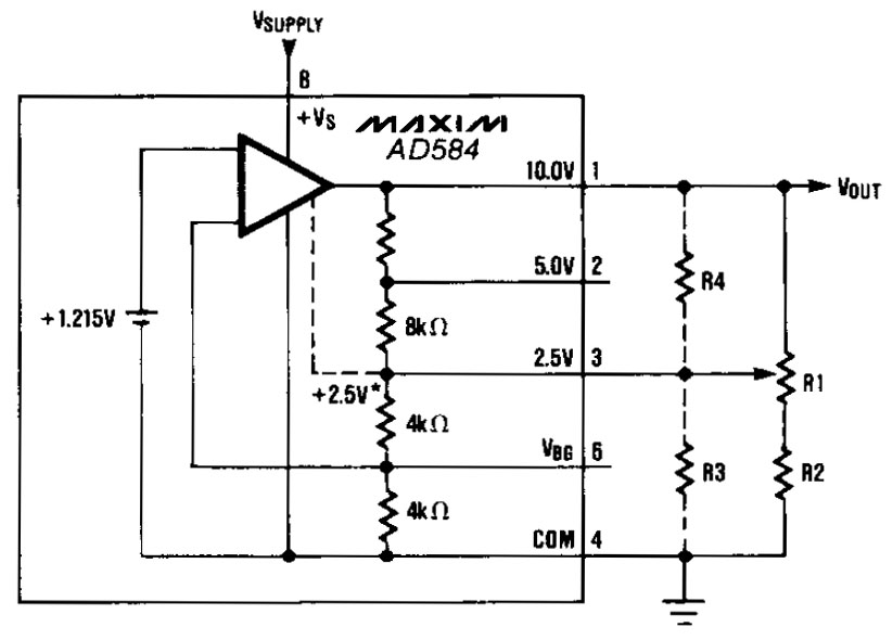


The AD584 offers four outputs: 10V, 5V, 2,5V and the bandgap voltage, which usually is 1,215V. The datasheet shows how to adjust the reference voltage to other values with additional resistors.
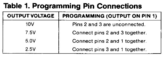


Depending on which output voltage you want to use, you can bridge different pins and thus adjust the internal voltage divider. In such a connection, the respective output offers the specified load capacity. If you use an external buffer, you can work without bridges and also access several of the output voltages.
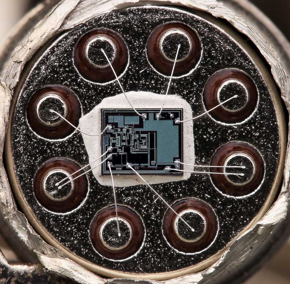


In the housing it can be seen that both the 10V reference potential and the reference potential are connected with two bondwires. Here, the connection has not simply been reinforced. On the die, the bondwires each contact different potentials.
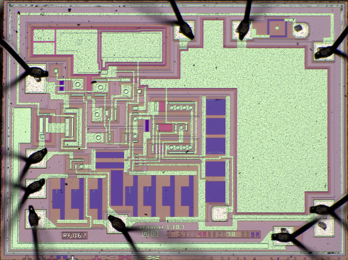
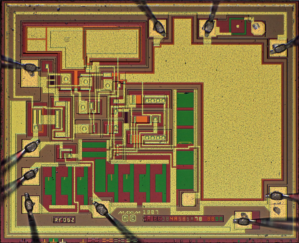


The dimensions of the die are 2,2mm x 1,8mm.


The design is obviously from Maxim and dates back to 1987.

Nine masks are depicted on the lower edge of the die. Many can be assigned to their function. 1A depicts the low-lying collector feed line. 2E creates the isolated areas. 4A represents a strong n-doping. Since the metal layer is preceded by mask 5B, it seems likely that 4A generates so-called sinkers, the connection between the low-lying n-dotations and the surface. 5B then generates the emitter regions. 6A creates openings in the silicon oxide through which the metal layer contacts the active elements. 7B then structures the metal layer. 9A obviously serves to define the shape of the adjustable resistors. 8B could be the mask that opens the passivation layer in the bond areas.

Some masks have been revised once. The mask for the isolated wells (2E), on the other hand, has been revised four times.


RF06Z seems to be the internal designation of the AD584. One can guess that at least a similar string is shown in the lower layers.
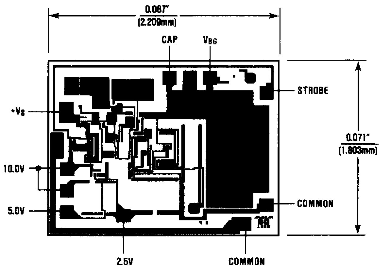


The Maxim datasheet for the AD584 contains an illustration of the metal layer that matches the present die very well. The only noticeable difference is in the bottom right corner, where the bondpad for the reference potential has been extended on the present die. The Maxim logo with the copyright had to be moved to the left accordingly.
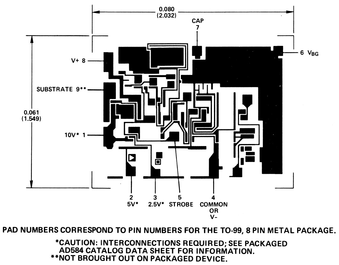
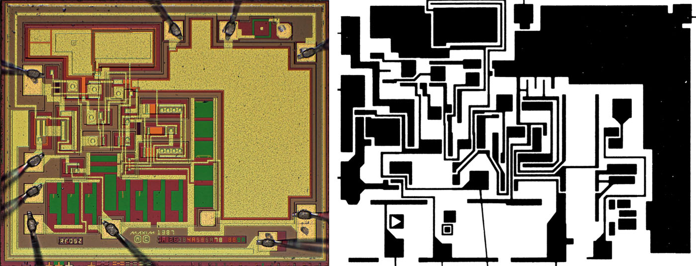


In the Analog Devices Data-Acquisition Databook from 1982, the metal layer of the Analog Devices AD584 is shown. This AD584 is slightly smaller than the Maxim model: 2,03mm x 1,55mm versus 2,2mm x 1,8mm.

You can see that the arrangement of the areas on the die is roughly the same. However, they are clearly two different designs.
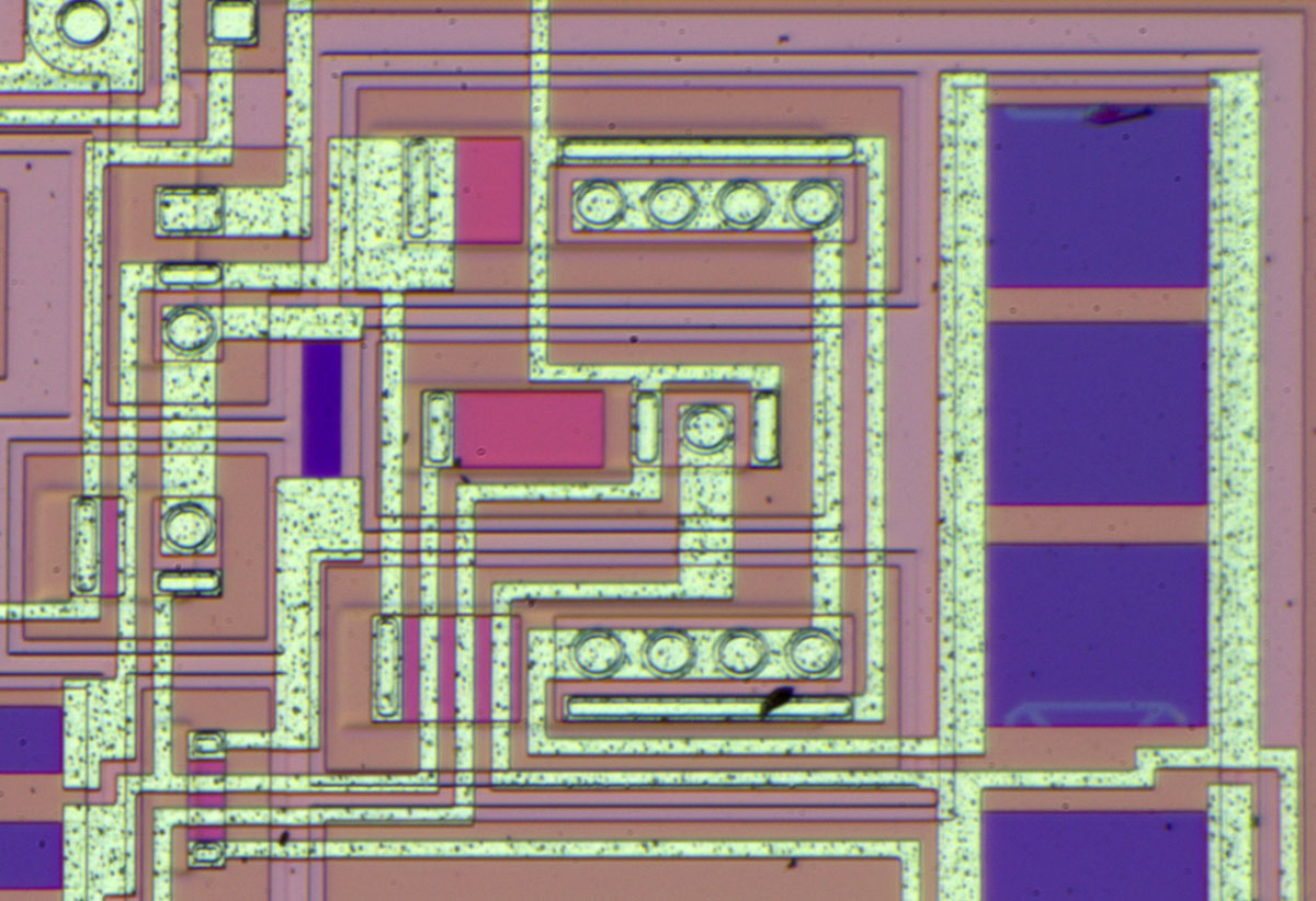


In the middle of the die, you immediately notice the typical bandgap structure, where a large transistor surrounds a small transistor. The ratio of the transistors here is 8:1. The working principle of a bandgap reference voltage source is described in more detail in the context of the AD1403 (https://www.richis-lab.de/REF16.htm).

In the right area there are adjustable resistors. The traces of the adjustment are clearly visible. It is interesting that not only a simple cut was made at the lower resistor. An area was cut off whose ends describe a kind of triangle.
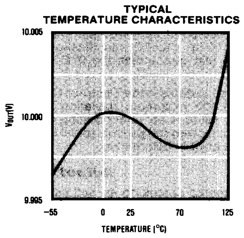


A bandgap reference compensates the negative temperature coefficient of the forward voltage of a pn junction with the positive temperature coefficient of the thermoelectric voltage of a pn junction. The datasheet of the AD584 shows the temperature variation of the output voltage and thus also that the compensation of the temperature coefficients is not perfect.
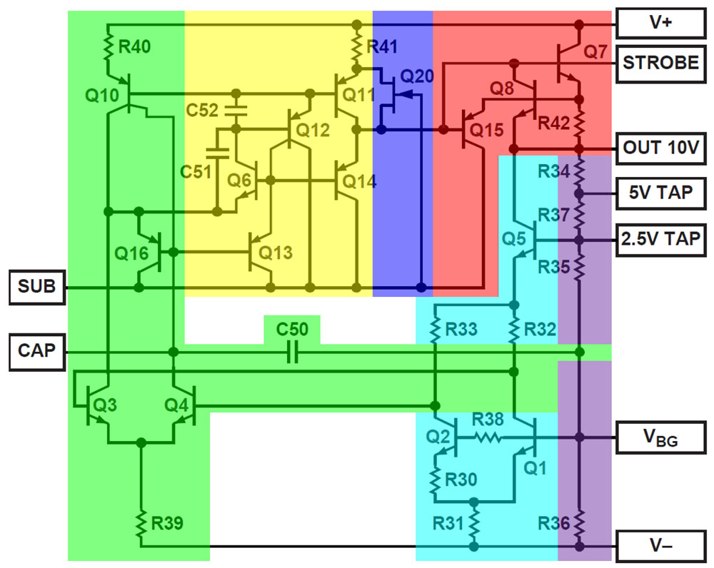


The datasheet from Analog Devices contains a complete circuit diagram for the AD584. As will become apparent, the circuit corresponds almost exactly to Maxim's circuit.

The core of the typical bandgap cell (cyan) is formed by the transistors Q1 and Q2. Q5 represents the associated current source. The 2,5V reference voltage is used to control this current source. This is also the reason why the datasheet points out that this node must not be trimmed more than 100mV.

The two branches of the bandgap reference are connected to a differential amplifier (green). The differential amplifier is supplied by Q10, which descripe two current sources. C50 reduces the noise of the reference output. For this reason, the package provides the CAP pin. Up to 100nF can be added externally between CAP and Vbg to further reduce noise.

The differential amplifier is followed by a somewhat unusual amplifier stage (yellow), at whose output is the push-pull stage Q11/Q14. C51 and C52 stabilise the circuit. It is interesting that this section is directly connected to the substrate. In principle, the substrate and the reference potential V- have the same potential, but the separation reduces the danger of disturbing feedback effects from the output driver to the reference voltage source.

Q20 (blue) ensures a safe start-up of the circuit. Q7 forms the output driver of the output stage (red). The output can be switched off with the strobe input. This pin is directly connected to the base of the output stage transistor. Q8 and R42 form an overcurrent protection. Transistor Q15 is a way of diverting the output current from Q7, which improves the control behaviour.

Below the 10V output is a resistor divider (purple) that maps the different output voltages.
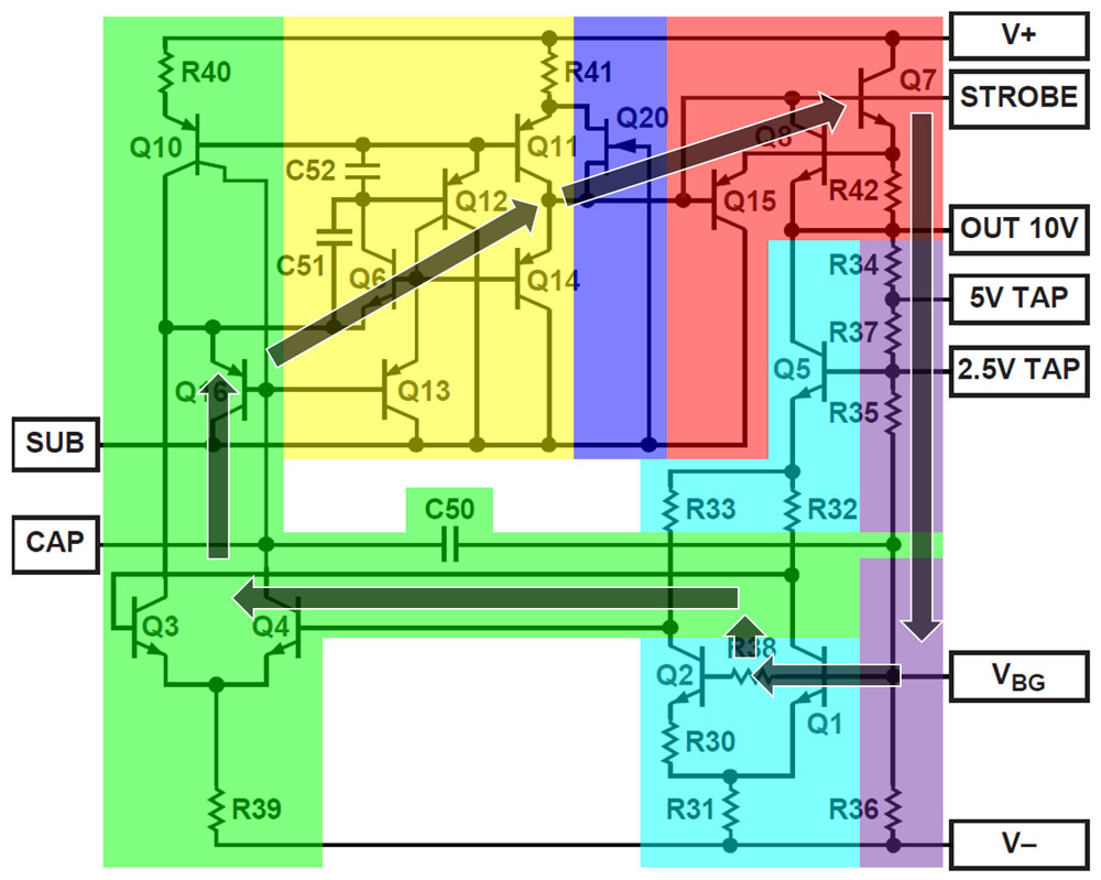


The control loop closes at the base of transistor Q1. At this point, the bandgap voltage is set at which the temperature coefficient becomes minimal. Since the control loop closes across the voltage divider, you can load the taps without changing the voltages. Of course, these taps are not as powerful as the 10V output. For this reason, you have to bridge outputs as described above if you want to fully load the lower output voltages.
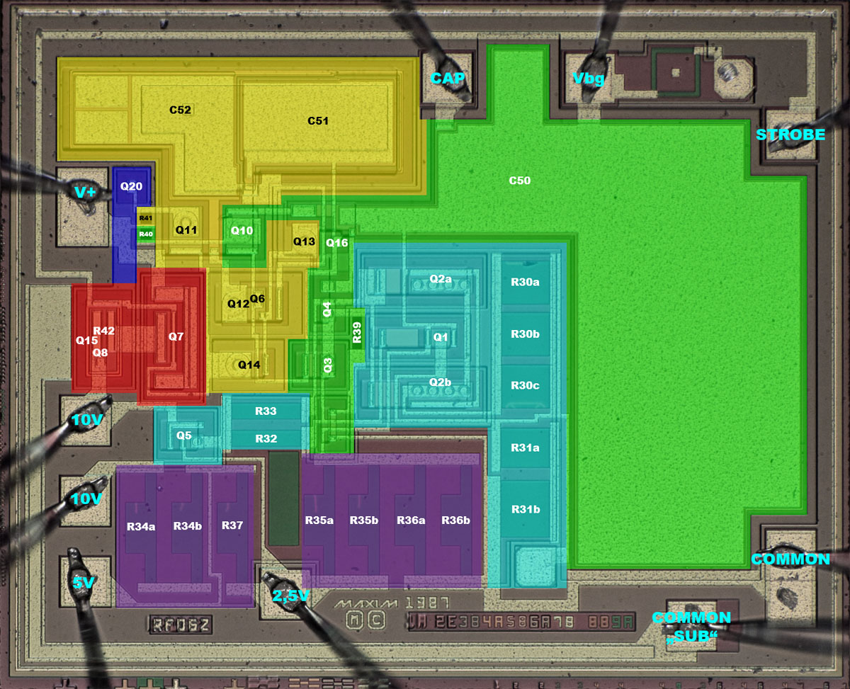


All the elements of the Analog Devices circuit diagram can be found on the die. Only resistor R38 is missing. The base current of the transistors Q1/Q2 flows through the voltage divider at the output. It varies with the amplification factor and thus also with the temperature, which creates an additional temperature drift. The influence can be compensated by a resistor between the transistors. Alternatively, the voltage divider can be designed with as low an resistance as possible. Since the output is relatively powerful, the voltage divider could probably be chosen with sufficiently low resistance and thus do without the base resistor.

In the upper right corner of the die is the familiar square structure that can be used to set the adjustment process. The resistors R30 and R31, which define the temperature coefficient of the reference voltage, are adjusted. A testpad under R31 facilitates the adjustment. Resistors R34-R37, which define the value of the individual reference voltages, are also adjusted. The resistor R39 in the current sink of the differential amplifier and the collector resistors R23/R33 are made of the same material, but the geometries are much smaller. Presumably, the material was not chosen for balancing, but for other reasons.



The output stage (red) and the critical elements of the bandgap reference (green/cyan) are arranged in such a way that the heat dissipation of the output stage affects the two paths of the bandgap reference as equally as possible.

The upper of the two 10V bondpads is connected to the output stage. From the 10V pin, the second bondwire then leads to the voltage divider on the die. This also compensates for the voltage drop across the bondwires. The reference potential is connected to the substrate over the entire lower edge and half of the left edge (blue). Next to the output stage, there is also a large-area contact to the substrate. The bandgap reference is connected to the reference potential via the second bondwire so that it is not influenced by load currents.
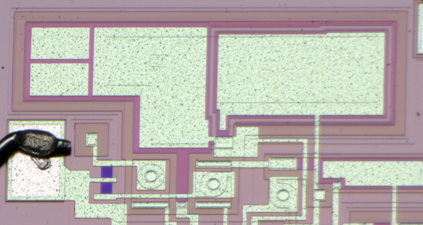
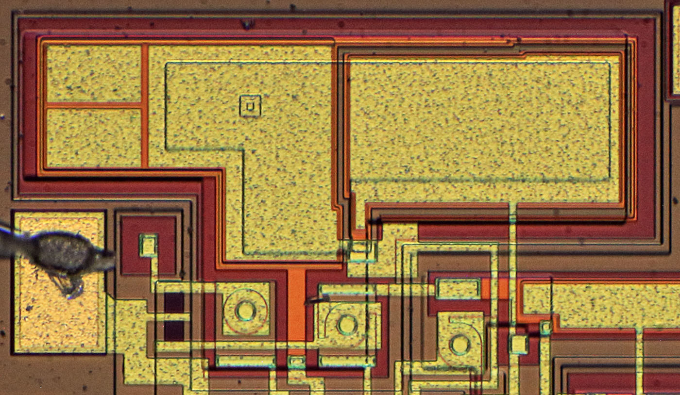


Capacitor C50 occupies almost half of the silicon area. In contrast, the capacitors C52 (left) and C51 (right) are much smaller. C51 is a classic capacitor, while C52 additionally uses the capacitance of the base-emitter junction. This can be seen in the contact window, which is visible in the metal layer. In the left area, the capacitance can be varied with two additional metal areas so that one can set an optimum between control speed and stability.
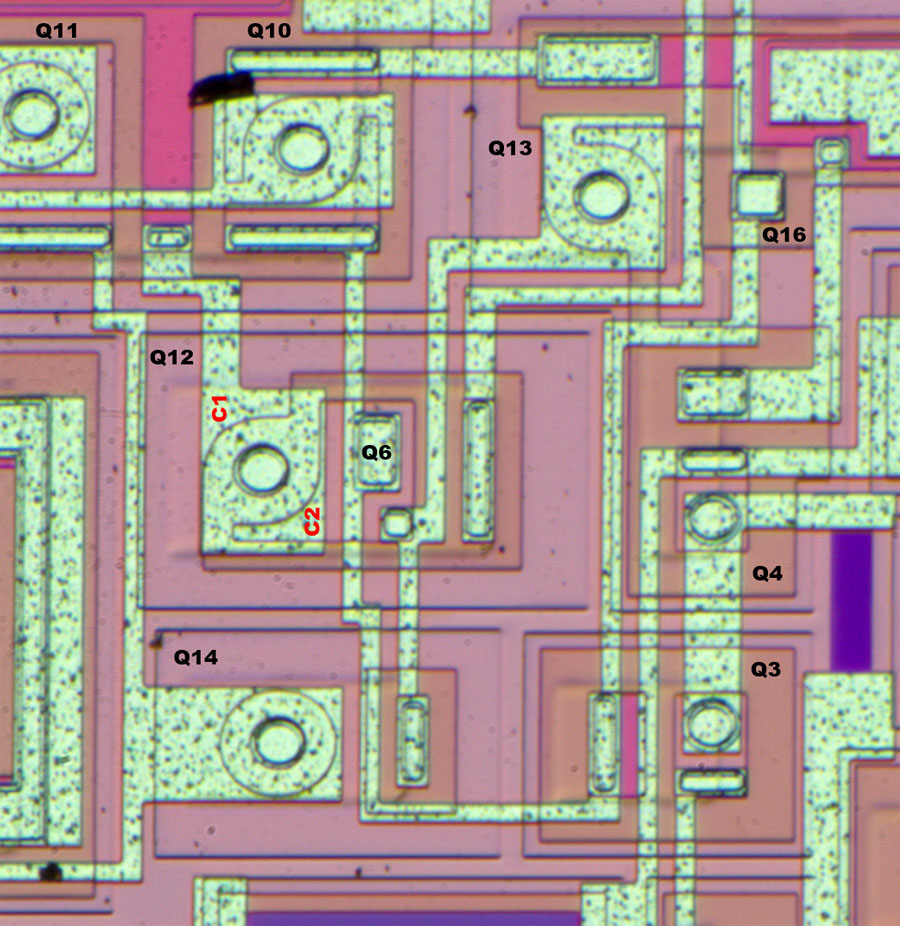


Usually, transistors are located in an n-doped well enclosed by p-doped regions. As long as the substrate has the most negative potential of the circuit, the wells are electrically isolated. This can be seen well in transistors Q3 and Q4, where the orange material represents the n-doping surrounded by the p-doping, which appears light pink. The slightly more prominent structures are p-doped frames that extend to the substrate.

As shown in the schematic, some transistors are directly connected to the substrate. This can be seen clearly in the case of transistor Q14, where the orange n-doping has only been introduced at the base contact. The collector is the p-doping surrounding all sides, which is directly connected to the substrate via the frame structure.

The transistor Q12 has two collectors. While C1 is directly connected to the substrate, as in Q14, C2 and its surroundings are somewhat more obscure. In the centre of the large metal surface is the circular, p-doped emitter, as usual for a PNP transistor. The ring around this circle is the n-doped base. The base area has been extended to the right and contains the p-doped collector C2, which is isolated from the substrate and is contacted in the lower right corner. In this p-doped collector area, an n-doping has again been introduced so that the NPN transistor Q6 can form there.

The PNP transistor Q16 is just as difficult to recognise. Here, the metal layer contacts a square, p-doped area that is completely covered by the metal layer. This area is located in an n-doped area, so that a substrate transistor is formed.


https://www.richis-lab.de/REF31.htm

 :-/O
 
The following users thanked this post: SeanB, Mickle T., Andreas, Jim Narem, BU508A, RoGeorge, ramon, alm, ch_scr, iMo, eplpwr

Online AnalogTodd

  • Regular Contributor
  • *
  • Posts: 85
  • Country: us
Re: More voltage references - die pictures
« Reply #94 on: June 29, 2023, 09:47:35 pm »

Interesting bits to take into consideration: this is a very basic bipolar process with the addition of two layers, the rich N-doping to get low resistance connections to the buried N-doping and a deposited resistor (likely sichrome) layer. Layer 1 is the buried N-doping and is not perfectly aligned in the mask revisions box because the shadow that appears on the surface of the die is offset from the actual location of the buried N-doping due to the crystal structure of the wafer and the epi growth process. Layer 2 is P-type isolation to define tubs for individual transistors and resistors, Layer 3 is the shallow P-base used for NPN transistor bases and lateral PNP emitter and collector diffusions, layer 4 is the deep N connection to the buried N, layer 5 is the shallow N+ for NPN emitters (and sometimes connection to layer 4). Layer 6 makes contact to the silicon, layer 7 is metallization, layer 8 is oxide/nitride passivation, and layer 9 is the deposited resistor layer.

The deposited resistor layer has some benefits such as being very resistant to mechanical stress on the die. The 8:1 transistor pair of Q1 and Q2 is centered in the die for avoiding mechanical stress as well. What is quite noticeable on the deposited resistors is the thin lines etched into a number of them. The shape of the resistors and those lines are hallmarks of laser trimming of the resistor values. Resistors R34, R35, and R37 are trimmed to match R36 and give precise output voltages. Trims are also seen on R30 and R31 to get the bandgap voltage as close to the magic voltage that provides a flat output across temperature. The targets to align the laser to the resistor positions are not seen on the die, they are likely in part of the scribe that was lost during wafer saw.
Lived in the home of the gurus for many years.
 
The following users thanked this post: RoGeorge, ramon, alm, razvan784

Offline NoopyTopic starter

  • Super Contributor
  • ***
  • Posts: 1726
  • Country: de
    • Richis-Lab
Re: More voltage references - die pictures
« Reply #95 on: June 30, 2023, 02:58:48 am »
The targets to align the laser to the resistor positions are not seen on the die, they are likely in part of the scribe that was lost during wafer saw.

As far as I know the rectangle in the upper right corner is used to align the laser. Perhaps there is another structure in the scribe line.

Online magic

  • Super Contributor
  • ***
  • Posts: 6749
  • Country: pl
Re: More voltage references - die pictures
« Reply #96 on: June 30, 2023, 08:26:34 am »
The resistor square in the top right corner looks like a test structure included to measure resistance of the thin film layer.

Analog Devices die revision D is on zeptobars.
R38 is also not included.
R31 includes a segment made of diffused resistor, which according to Brokaw was intended for curvature correction. Not sure why Maxim doesn't have it.

The differential amplifier is followed by a somewhat unusual amplifier stage (yellow), at whose output is the push-pull stage Q11/Q14. C51 and C52 stabilise the circuit.
The output stage is driven from Q4 collector by a straightforward darlington emitter follower Q13,Q14.
Q11 contribution to output stage control seems negligible due to its collector having much higher output impedance than Q14 emitter. That being, it is a mirror of Q3 collector current so it works in phase with Q4 and Q14.
Q6 allows Q3 to drive the PNP current mirror while having constant collector voltage roughly equal to Q4, this improves PSRR at Q3/Q4 and more importantly at Q10 (lousy lateral PNP with low Early voltage).
Current injected into Q3 by Q6 is the base current of Q12, while Q4 receives the base current of Q13.
The weird splitting of Q12 ensures that these currents are equal (Q12 passes base currents of Q10+Q11, Q13 half of the former plus base current of Q14).
« Last Edit: June 30, 2023, 09:25:24 am by magic »
 
The following users thanked this post: Noopy

Online AnalogTodd

  • Regular Contributor
  • *
  • Posts: 85
  • Country: us
Re: More voltage references - die pictures
« Reply #97 on: June 30, 2023, 02:57:38 pm »
The targets to align the laser to the resistor positions are not seen on the die, they are likely in part of the scribe that was lost during wafer saw.

As far as I know the rectangle in the upper right corner is used to align the laser. Perhaps there is another structure in the scribe line.
As magic noted, the structure in the top right appears to be a test structure of some sort. No reason to have connections to it from any bond/probe pads. It is possible they designed it to also be a laser alignment target, but a second target is also necessary at the opposing corner of the die to align the laser on each die, and it should be on the deposited resistor layer.
R31 includes a segment made of diffused resistor, which according to Brokaw was intended for curvature correction. Not sure why Maxim doesn't have it.
A lot of the reason for diffused resistor usage isn't just curvature correction, it's correction for the temperature coefficient of the resistors used in creating the bandgap to get it exactly to 1.25V and as flat as possible. Look at a number of different products out there and you'll find that reference voltages aren't always 1.25V, sometimes they are 1.24V, 1.21V, etc. Depending on the process, the flattest bandgap voltage isn't always 1.25V. Add a resistor in there that has a different TC and you can dial things in to the point you want (first-order correction). Second- and third-order correction takes a fair bit more to do. The LT6657 (A-grade) is probably one of the best transistor based references out there at guaranteed 1.5ppm/deg. C over the -40 to 125C range (typical parts are better than 1ppm/deg. C, often around 0.5ppm/deg. C). The method used to achieve that is ingenious.
Lived in the home of the gurus for many years.
 
The following users thanked this post: magic, Noopy

Offline NoopyTopic starter

  • Super Contributor
  • ***
  • Posts: 1726
  • Country: de
    • Richis-Lab
Re: More voltage references - die pictures
« Reply #98 on: June 30, 2023, 08:23:34 pm »
I just can say I found these rectangles on nearly every die with laser trimming and never on a die without laser trimming...  ;)


The output stage is driven from Q4 collector by a straightforward darlington emitter follower Q13,Q14.
Q11 contribution to output stage control seems negligible due to its collector having much higher output impedance than Q14 emitter. That being, it is a mirror of Q3 collector current so it works in phase with Q4 and Q14.
Q6 allows Q3 to drive the PNP current mirror while having constant collector voltage roughly equal to Q4, this improves PSRR at Q3/Q4 and more importantly at Q10 (lousy lateral PNP with low Early voltage).
Current injected into Q3 by Q6 is the base current of Q12, while Q4 receives the base current of Q13.
The weird splitting of Q12 ensures that these currents are equal (Q12 passes base currents of Q10+Q11, Q13 half of the former plus base current of Q14).

That sounds very reasonable. Thanks!  :-+


R31 includes a segment made of diffused resistor, which according to Brokaw was intended for curvature correction. Not sure why Maxim doesn't have it.
A lot of the reason for diffused resistor usage isn't just curvature correction, it's correction for the temperature coefficient of the resistors used in creating the bandgap to get it exactly to 1.25V and as flat as possible. Look at a number of different products out there and you'll find that reference voltages aren't always 1.25V, sometimes they are 1.24V, 1.21V, etc. Depending on the process, the flattest bandgap voltage isn't always 1.25V. Add a resistor in there that has a different TC and you can dial things in to the point you want (first-order correction). Second- and third-order correction takes a fair bit more to do. The LT6657 (A-grade) is probably one of the best transistor based references out there at guaranteed 1.5ppm/deg. C over the -40 to 125C range (typical parts are better than 1ppm/deg. C, often around 0.5ppm/deg. C). The method used to achieve that is ingenious.

I had the same thoughts as magic. There is a curvation correction missing. The temperature characteristic graph shows that there should be one.  :-//

Online AnalogTodd

  • Regular Contributor
  • *
  • Posts: 85
  • Country: us
Re: More voltage references - die pictures
« Reply #99 on: July 02, 2023, 02:52:22 pm »
R31 includes a segment made of diffused resistor, which according to Brokaw was intended for curvature correction. Not sure why Maxim doesn't have it.
A lot of the reason for diffused resistor usage isn't just curvature correction, it's correction for the temperature coefficient of the resistors used in creating the bandgap to get it exactly to 1.25V and as flat as possible. Look at a number of different products out there and you'll find that reference voltages aren't always 1.25V, sometimes they are 1.24V, 1.21V, etc. Depending on the process, the flattest bandgap voltage isn't always 1.25V. Add a resistor in there that has a different TC and you can dial things in to the point you want (first-order correction). Second- and third-order correction takes a fair bit more to do. The LT6657 (A-grade) is probably one of the best transistor based references out there at guaranteed 1.5ppm/deg. C over the -40 to 125C range (typical parts are better than 1ppm/deg. C, often around 0.5ppm/deg. C). The method used to achieve that is ingenious.

I had the same thoughts as magic. There is a curvation correction missing. The temperature characteristic graph shows that there should be one.  :-//
Looking at the temperature characteristic graph, the rise in the reference voltage above 70C may not be due to any curvature correction but instead from leakage current in the device. Oftentimes, curvature correction may be put in as a second transistor that is off at low temperatures and turns on as temperature rises. This requires setting the initial bandgap low, such that if there was no second transistor the 'peak' of the bow would be at low temperature and overall would show a strongly negative TC at higher temperature. When the second transistor turns on, it creates a second bow that adds in, creating a 'double hump' characteristic across temperature. I have seen circuits that even use a third transistor to try and flatten things as much as possible. This is called 'breakpoint' compensation where I have run into it.

The problem with trying to use a second type of resistor to flatten a reference is that the process is quite often severely limited in the types of resistors available and their temperature characteristics. You would quite literally want resistor types that have exact first order temperature coefficients to get the 1.25V as flat as possible as well as second order coefficients that would oppose the bow inherent in a transistor-based bandgap reference. Don't forget how well the multiple resistor types will need to match in the process...good luck!

The way I can tell this is leakage currents is the shape of the curve. Leakages start to show across temperature as a function of the operating quiescent current--the more micropower the part (and the bigger the devices) the sooner it becomes an issue. Leakage currents are exponential with temperature, which is what is being seen in the temperature characteristic graph; the 10V reference starts climbing exponentially above 100C. You can even infer how it will happen via looking at the layout and the circuit: Q2 has more than twice the tub area and periphery than Q1 so it will leak significantly more, lowering the base of Q4 relative to Q3 and that will eventually raise the output voltage. Newer products now will actually work to balance leakages so you don't see this characteristic, this design uses the leakage to oppose what would normally be a slightly negative temperature characteristic.

The absolute flattest temperature curves I have seen use a completely different type of curvature correction that totally cancels the second order effects. Can't discuss more than that as it is patent pending for a previous employer (last I knew of it, still haven't seen the patent issued yet).
Lived in the home of the gurus for many years.
 
The following users thanked this post: RoGeorge, Noopy

Offline NoopyTopic starter

  • Super Contributor
  • ***
  • Posts: 1726
  • Country: de
    • Richis-Lab
Re: More voltage references - die pictures
« Reply #100 on: July 02, 2023, 07:46:20 pm »
...

Very interesting! Thanks for the extensive explanation!  :-+


I have one more: The MC1403 reference was developed by Motorola. According to the datasheet, it is comparable to the AD580 (https://www.richis-lab.de/REF28.htm). The output voltage is 2,5V with a tolerance of +/-25mV. The temperature drift is typically 10ppm/°C.


The datasheet of the MC1403 shows a temperature drift typical for a bandgap reference. The output voltage first rises and then falls again. ...but just up to 85°C.  ;)


The datasheet of the MC1403 contains a detailed circuit diagram. The designations of the transistors have been added here. This is the typical bandgap circuit. The multiple contacting of the 1kΩ resistor is a way of setting the temperature coefficient to a minimum.


The MC1403 uses just three pins of the package.


From the side, it is easy to see that the die was just partially cut and then broken out of the wafer.


The dimensions of the die are 1,3mm x 1,0mm.


Under a contact to the substrate one can guess a character string in some pictures. It seems there are the characters AP9.


The integrated circuit corresponds exactly to the circuit diagram. However, there is an unused bondpad in the upper right corner. In the lower right corner, this potential contacts a small structure that is connected to GND. It could be a pn structure that could be used for a temperature measurement.

The 1kΩ resistor is obviously adjustable, but also the 5,61kΩ resistor at the right edge offers possibilities to vary the resistance. Here, however, one has to adjust the mask of the vias. The metal surfaces are so large that they can reach the vias over a relatively large area.


The adjustable 1kΩ resistor has an unusual design. A simple resistor, a strip of the base doping, has been used. Underneath the resistor are 17 thin metal strips that were partially cut. Probably a laser was used here. The isolated square on the far left seems to have served to align the laser. A cut-out in the passivation layer is not visible. It was probably possible to cut the wires safely without such a cut-out.

The cut strips look somewhat dirty. This can be problematic if currents are still flowing through the debris. The behaviour of such areas can change over time and thus negatively influence the temperature drift of the reference.


The 30pF capacitor of the MC1403 is not immediately visible. It must be connected to GND on one side. The other side is connected to the collector of T6, the base of T4 and the collector of T2. No typical capacitor structure can be seen on the die. Consequently, the capacitance must be integrated in the areas of the active structures.

No larger capacitance is found in the areas of T6 and T2. This leaves just the transistor T4. A certain capacitance towards the substrate is formed by the buried collector of T2, which is a base contact for the transistor T4. This heavily n-doped layer rests directly on the substrate and has been extended from T2 to below T4 to represent the electrical connection between T2 and T4. However, this region alone does not represent 30pF.

As substrate PNP transistors, T4 and T5 just require an inner p-region and a surrounding n-frame. In cross-section, of course, it is not an n-frame, but an n-layer under the p-region. Although it would not be necessary, an outer p-region has been integrated here too. Most likely, the p-doping represents a large part of the 30pF capacitance. In contrast to the transistors T5, T6 and T2, T4 is not located in a n-doped well. As a result, the large p-doped area is electrically connected to GND and a capacitance is formed between the n-doped base area of the PNP transistors and the p-doped layer above it (green).


https://www.richis-lab.de/REF32.htm

 :-/O
 
The following users thanked this post: SeanB, Jim Narem, BU508A, RoGeorge, floobydust, alm, ch_scr

Offline NoopyTopic starter

  • Super Contributor
  • ***
  • Posts: 1726
  • Country: de
    • Richis-Lab
Re: More voltage references - die pictures
« Reply #101 on: July 08, 2023, 07:54:05 pm »


The above table from "Linear/Interface ICs Devices Data Vol. II" shows the voltage references that Motorola sold 1993. Beside the shunt regulator TL431 there is the LM385, the MC1403 and the MC1404. MC1403 and MC1404 are specified very similar. The MC1404 offers two additional functional pins and could be purchased with different output voltages: 5V, 6.25V and 10V.


In contrast to the MC1403, only a simplified circuit diagram is shown in the MC1404 datasheet. Accordingly it contains a typical bandgap reference.

Compared to the MC1403, the MC1404 in addition has the potentials Vtemp and Trim. The output voltage can be adjusted via the pin Trim. There is no application for the potential Vtemp. One could realize a temperature measurement with it. However, it does not seem to make much sense to use the core area of the bandgap reference for such additional functions.


The reference potential of the MC1404 is connected to the outside with two bondwires.


The dimensions of the die are 1,4mm x 1,1mm. In the upper right corner you can find the string BC5.


The circuit is quite clear. In the right area there are two unused PNP transistors.


As expected, the MC1404 is a classic bandgap reference. The core of the reference is built the same way as in the MC1403. The bias circuit is slightly different and there are some minor details.

In the MC1403 the bias current is generated based on the reference voltage. A JFET ensures a safe start-up of the circuits. In the MC1404, the JFET current source Q12/R11 generates the bias current out of the supply voltage. With this background, it seems only logical that the MC1404 compensates fluctuations of the supply voltage somewhat worse than the MC1403.

Above R5/R6 there is the transistor Q9, which is connected as a diode. The potential above the transistor is connected to the surface on which resistors R5/R6 are integrated. This probably was done to reduce leakage currents from the resistors.

In the supply of the current mirror Q7/Q8 with Q10 an additional diode path has been inserted. The capacitor C1 is integrated in the area around the transistors Q3/Q4 as on the MC1403.

The voltage divider R7/R8 is constructed with eight resistor strips. The symmetrical arrangement of R8 around R7 ensures that temperature drifts have a similar effect on both resistors. If you connect the resistors differently, you can set the different output voltages. This is achieved by varying the metal mask, in which the string 10V is shown too. The wide metal areas above the contacts allows a slight adjustment of the resistors and thus the output voltage. To do this, one has to change the mask for the contacts between silicon and metal.


The resistors R1 and R3 define the temperature drift of the reference voltage. As with the MC1403, the values of these resistors can be varied by modifying the contact mask.

The temperature drift is tuned at the resistor R2. As in the MC1403, metal leads were cut with a laser. An element for aligning the laser is shown in the upper left corner. Nevertheless, the laser was set very far down, so that it already has cut through the thicker areas of the leads. There is a risk that the resistive strip has been directly affected and these areas then change their behavior over time.


https://www.richis-lab.de/REF33.htm

 :-/O
 
The following users thanked this post: SeanB, Mickle T., Jim Narem, BU508A, RoGeorge, alm, ch_scr, iMo

Offline NoopyTopic starter

  • Super Contributor
  • ***
  • Posts: 1726
  • Country: de
    • Richis-Lab
Re: More voltage references - die pictures
« Reply #102 on: July 22, 2023, 07:57:20 pm »


This voltage reference was found in a Motorola Optobus transceiver (https://www.richis-lab.de/transceiver03.htm).


The metal layer reveals that it is a Motorola design. The internal designation is apparently C91J. The metal layer also shows that the output voltage is 2.5V.


The die offers a surprisingly large number of interfaces. Thus, the reference voltage can be tapped in the lower right corner and at the upper edge. Both interfaces additionally have a bondpad for a feedback of the voltage. As with the MC1404 reference voltage source, the bandgap potential Vtemp can also be tapped and the reference voltage can be adjusted via Vtrim.


The left part of the circuit is very similar to the MC1404. Just R3 and R4 have been added here. The output stage with the feedback to the bandgap reference is similar too. However, the output is much more robust. Q11/Q12 serves as a Darlington transistor and D3 represents a freewheeling diode.

The bias current generation and the current limitation at the output are much more complex than in the MC1404. The central block Q18-Q22 seems to generate a reference current which is fed into the circuit via Q13. If the voltage drop across R15 is too high, the bias current is diverted by the current mirror Q15/Q16 and thus the output stage driving current is reduced.

If you find a mistake let me know!


The resistors of the voltage divider R11/R13 are located in a field with eight resistor stripes flanked by two dummy structures. For the output voltage of 2,5V, just the two innermost resistor stripes are used. The other stripes are contacted but do not affect the voltage divider in this connection.


The four testpads in the left area activate up to four resistors that adjust the temperature coefficient of the reference voltage. The resistors consist of parallel connected strips with dummy structures and offer a ratio of 1:2:4:8.

In the right part of the image, you can see the transistor structures typical of a bandgap reference. Two larger, parallel-connected transistors (Q1a/Q1b) are placed above and below a smaller transistor (Q2). To the right of the center transistor are three resistor strips, two of which are connected in parallel and tied between the bandgap reference transistors (R3). The ideal value at this point is determined by the resistance of the voltage divider in the feedback loop (R13). Since the voltage divider can be adapted for different output voltages, it makes absolutely sense to adapt the resistors between the transistors accordingly.


The above table from the catalog "Linear/Interface ICs Devices Data Vol. II" shows the range of reference voltage sources that Motorola had in its program in 1993. None of them fits to the present circuit. The TL431 and the LM385 are shunt regulators. The MC1403 (https://www.richis-lab.de/REF32.htm) and the MC1404 (https://www.richis-lab.de/REF33.htm) are much simpler. Perhaps the voltage reference documented here is a special development that was never offered separately.


https://www.richis-lab.de/REF34.htm

 :-/O
 
The following users thanked this post: SeanB, Andreas, BU508A, RoGeorge, alm, ch_scr, iMo

Offline NoopyTopic starter

  • Super Contributor
  • ***
  • Posts: 1726
  • Country: de
    • Richis-Lab
Re: More voltage references - die pictures
« Reply #103 on: August 21, 2023, 03:52:04 am »


EDIT: For the latest analysis and information regarding the MAA550 take a look at the pictures and discription following the TAA550 in the next post.
« Last Edit: September 24, 2023, 07:12:17 pm by Noopy »
 
The following users thanked this post: SeanB, Mickle T., Andreas, doktor pyta, Jim Narem, BU508A, RoGeorge, ch_scr, iMo

Offline NoopyTopic starter

  • Super Contributor
  • ***
  • Posts: 1726
  • Country: de
    • Richis-Lab
Re: More voltage references - die pictures
« Reply #104 on: September 21, 2023, 08:15:42 pm »


Ignore the MAA550 we had there will be an update soon. Here we have some new insights starting with a TAA550 from Tungsram. The development goes back to Valvo. One of the first advertisements promoting the TAA550 can be found in the magazine Electronics in December 1968. The TAA550 has been copied by many manufacturers over the years.


The application you can see here is taken from the "Philips Data handbook - Semiconductors and integrated circuits" published in March 1977. The filtering of the output is interesting. A CRC circuit is recommended instead of a simple capacitor. In an article in the magazine Electronics (December 1969), Valvo warns you shouldn´t connecting capacitors with more than 4,7nF directly to the output of the TAA550. Otherwise, in the event of a short circuit, oscillations between the line inductance and the capacitor must be expected, the negative voltages of which will damage the TAA550.


Due to the high reference voltage, the power dissipation that occurs in the TAA550 is not insignificant. The minimum required operating current is 2mA, 5mA is specified as a typical value. With this current, up to 175mW is generated. The datasheet shows that the typical current without heat sink is only permissible up to an ambient temperature of about 60°C.


In the magazine Electronics from December 1969 (Volume 42) there is an article in which Valvo describes the construction and the functionality of the TAA550. There is also the above schematic shown, which at first sight seems very confusing.

An obvious and unusual feature of the TAA550 is the fact that the substrate is connected to the positive supply potential. Apart from special exceptions, integrated circuits in bipolar technology have actually always had the substrate connected to the most negative potential of the circuit.

The resistors are drawn with their parasitic diodes. In normal operation, these never become conductive. In the short circuit case described at the beginning, however, they are critical. Already at -1V at the TAA550 one has to expect high currents across the diodes.

The circuit contains three transistors with two emitters each. The functionality is not readily apparent with this illustration.


The above schematic is from the 1975/1976 SGS ATES Databook. Transistors Q8 and Q9 represent a Darlington circuit that adjusts the reference voltage by allowing more or less current to flow through the device. The reference voltage is the result of all base-emitter and emitter-base voltages of the circuit. Here, the transistors with the two emitters are each shown as two individual transistors. In one, the base-emitter path is operated in the flux direction (Q3, Q5, Q7), and in the other, it is operated in the reverse direction, acting as a Z-diode (Q2, Q4, Q6).

The transistor Q1 forms a so-called "Vbe multiplier" with the surrounding resistors. The circuit multiplies the base-emitter voltage so that about 1,9V drops across it. The voltage drop across the Darlington output stage is about 1,3V. The voltage drop across transistors Q3, Q5, Q7 is about 2,0V. Thus, the Z-diodes must have Zener voltages in the range of 8,3V to 10V. This is consistent with the article in magazine Electronics, where Valvo specifies an emitter-base breakdown voltage of 8-10V as a target.

As with many reference voltage sources, the positive temperature coefficient of the Z-diodes in the TAA550 is balanced by the negative temperature coefficient of pn junctions conducting in forward direction. However, the high reference voltage requires the somewhat more complex circuit.


The temperature coefficient of a Z-diode depends on its Zener voltage. Microsemi shows the above behavior in its Micro Notes (203). From a Zener voltage of about 5V, the value becomes positive, whereby the temperature coefficient in this transition range also depends very strongly on the current. At 8-10V one would have to calculate with 0,055-0,065%/K (4,4-6,5mV/K). Assuming that the Z-diodes in the TAA550 behave similarly, they should bring a temperature drift of 13,2-19,5mV/K in total.

A single pn junction, on the other hand, offers a temperature coefficient of just -2mV/K. For this reason, in addition to the Darlington transistors Q8 and Q9, the circuit also contains the transistors Q3, Q5, Q7 working as diodes. This results in a total value of -10mV/K. The missing contribution is provided by the Vbe multiplier around Q1. It multiplies not only the base-emitter voltage itself, but also its temperature coefficients. With the previous estimation, the multiplier should be 1,6-4,8.


The purpose of the three R3, R4, R5 is not obvious at first glance. They are necessary because the special design of the TAA550 can lead to a problematic behavior. This becomes clearer if the circuit is drawn a little differently and simplified. Here you can see that the transistors Q3, Q5 and Q7 have the potential to behave like a chain of Darlington transistors. The current flow through the collectors would cause the transistors to saturate and there would be no longer a useful reference voltage.

To prevent this, resistors R3, R3 and R5 have been integrated. They sink the collector current and thus prevent it from becoming effective in the base-emitter junction. As the collector-base voltage and thus also the collector current increase downwards, the values of the resistors become smaller: 1,1kΩ / 1kΩ / 0,9kΩ.


Here you can see the inside of the package. The end of the bondwire is strange. They left it quite long ending with a molten ball.


A transparent potting protects the die from environmental influences. It can be dissolved with paint stripper and then removed.


The edge length of the die is 0,55mm. Next to the bondpad is a T like Tungsram used as a logo. The typical dichotomy was implemented with the base and emitter doping. As a side effect, you can use the logo to see how well the two masks are aligned with each other.


The most striking feature of TAA550 is the absence of isolated wells. All elements are located in the n-doped substrate. For this reason, the substrate here is connected to the positive supply potential via the package. In the upper left corner of the die is where the positive supply potential is fed into the circuit.

Q1, Q8 and Q9 are constructed like normal transistors except for the missing isolation to the substrate. The other transistors each have two blue emitter areas in the green base area. This can be seen especially well with the double transistor Q4/Q5. The output stage transistor Q9 is much larger to show a sufficient current carrying capacity.

The resistors R3 and R4 appear to be similar in size. R5, on the other hand, is noticeably smaller.


The resistor R1 consists of three elements. Depending on which multiplier you need for transistor Q1, you can bridge the resistors by changing the metal layer. However, this is not an individual tuning of one part. The manufacturing process must be stable enough that once the temperature coefficient has been set, it remains sufficiently constant through the batch. Roughly estimated, the multiplier can be adjustable in the range between 1,6 and 4,3. In this TAA550, the factor is  something around 2,9, which seems plausible.


https://www.richis-lab.de/REF36.htm

 :-/O
« Last Edit: September 24, 2023, 07:14:21 pm by Noopy »
 
The following users thanked this post: SeanB, Jim Narem, BU508A, RoGeorge, alm, ch_scr

Online RoGeorge

  • Super Contributor
  • ***
  • Posts: 6177
  • Country: ro
Re: More voltage references - die pictures
« Reply #105 on: September 21, 2023, 09:33:40 pm »
Funny looking that transparent potting.  8)
Makes one want to decapsulate a TAA550 and shine a LED at it, so to make a light-tuned voltage reference.  ;D

Offline NoopyTopic starter

  • Super Contributor
  • ***
  • Posts: 1726
  • Country: de
    • Richis-Lab
Re: More voltage references - die pictures
« Reply #106 on: September 22, 2023, 02:55:59 am »
Funny looking that transparent potting.  8)
Makes one want to decapsulate a TAA550 and shine a LED at it, so to make a light-tuned voltage reference.  ;D

Should be possible...  ;D

Online dietert1

  • Super Contributor
  • ***
  • Posts: 2052
  • Country: br
    • CADT Homepage
Re: More voltage references - die pictures
« Reply #107 on: September 22, 2023, 06:16:52 am »
Thanks for this interesting report.

Some days ago i was working on something similar, but i ended up using a "RefAmp" design (6.2 V zener + npn transistor) with a voltage divider (27K, 7K1) to make a temperature stable 33 V supply.

Regards, Dieter
 

Offline NoopyTopic starter

  • Super Contributor
  • ***
  • Posts: 1726
  • Country: de
    • Richis-Lab
Re: More voltage references - die pictures
« Reply #108 on: September 24, 2023, 07:09:17 pm »


Now lets take a new look into the Tesla MAA550, the reproduction of the TAA550. Here we have the first variant. FX stand for a production in May 1974.


The Radio Fernsehen Elektronik (13 / 1972) shows some further information about the MAA550. For example, it can clearly be seen that the MAA550 requires a bias current of at least 1mA. The specifications apply to a current of 5mA. At the same time, the text describes that the load from the connected circuit should not exceed 1mA.


The datasheet of the MAA550 contains the above circuit diagram. The operation is the same as the operation of the TAA550. Here the three transistors with the two emitters are shown as Z-diodes and normal diodes.


The dimensions of the die are 0,58mm x 0,57mm. As in the TAA550, no isolated areas can be seen.


Right below the bondpad is the contact to the substrate and thus to the P-potential. The resistor R1 consists of four elements which can be short-circuited via the metal layer. On the transistor T1 there is an unused contact. It is the base contact, which is not necessary, because the resistor R1d connects directly to the base area.

As in the TAA550, the diodes in the MAA550 are realized as transistors with two emitter areas. The three resistors R3, R4 and R5 are specified in the schematic with 800Ω each. If you look at the geometries on the die, you can clearly see that the lengths and thus the resistor values become smaller from top to bottom, as in the TAA550. The square output stage transistor T3 seems to be minimally smaller than the output stage transistor in the TAA550.


An estimation of the resistance values shows that the factor of the Vbe Multiplier can be set in the range between 1,6 and 4,0. With the metal layer we can see here, the factor is 3,4.


The MAA550 seen here was labeled in red. A datecode is not printed on the package.


The metal layer is severely damaged. On the center transistor at the lower edge, one contact is almost completely broken. Perhaps the device was thermally overloaded.


The MAA550 seen here carries the datecode BY1 and was thus manufactured in May 1977.


In the package there is a very badly damaged die. During production, the upper right corner was broken off. The metal layer shows clear signs of corrosion. The rest of the surface appears to be heavily soiled. It is hard to say what happened. Perhaps there were impurities in the package that attacked the surface over time.


https://www.richis-lab.de/REF37.htm

 :-/O
 
The following users thanked this post: SeanB, chickenHeadKnob, Jim Narem, BU508A, RoGeorge, ch_scr

Offline NoopyTopic starter

  • Super Contributor
  • ***
  • Posts: 1726
  • Country: de
    • Richis-Lab
Re: More voltage references - die pictures
« Reply #109 on: September 24, 2023, 07:10:24 pm »


This MAA550 is the second variant of the MAA550. It shows the datecode W5. It was therefore manufactured in May 1988. It is noticeable that the three MAA550 of variant 1 were also manufactured in May.


The connection of the bondwire with the pin does not appear particularly stable.


The edge length of the die is 0,49mm. One difference to the MAA550 variant 1 and to the TAA550 is immediately noticeable: Here the transistors are located in separated areas. This suggests that a common bipolar process was used. This would mean that the substrate is p-doped, the dark green areas are n-doped collector areas and the light green boundaries with a p-doping isolate the collector areas against each other.

However, since the positive potential is still connected to the substrate in the MAA550, the individual areas do not remain completely isolated. Current can still flow from the positive supply potential to the active elements through the junction. The junction acts like a diode in that place.


The first variant of the MAA550 has the same design as the TAA550. The second variant shown here differs not only in the basic construction, but also the circuit has been simplified. The three diodes and their parallel resistors are missing here.

The P potential is connected to the substrate via the package. At the upper edge, resistor R1 is connected to the frame structure. This means that the frame must be connected to the P potential. No structures can be seen under the frame. Presumably, the frame in the edge region contacts both the n-doped collector surfaces and the p-doped isolation frames and thus the substrate. This makes sense, since otherwise there would be diodes in all collector paths. However, these diodes would probably not affect the function.

Transistor T1 is clearly visible. D1, D3 and D5 are further transistors, but they are operated inversely and thus serve as Z-diodes. T2 is again connected as a normal transistor and drives the larger transistor T3, which contains three emitter areas.


Apparently, it was decided to represent the necessary negative temperature coefficient via the Vbe multiplier and the Darlington stage. Fittingly, the geometries of the resistors R1 and R2 show that their values were chosen differently than shown in the schematic. The ratio here is up to 31/6 instead of only 20/8, resulting in a negative temperature coefficient of up to -12.3mV/K, with the Darlington transistors -16.3mV/K.
Assuming the same temperature coefficients for the Z-diodes as for the TAA550 (13.2-19.5mV/K), the compensation range of the Vbe Multiplier should be sufficient.


The transistors, which work as zenerdiodes in avalanche breakdown, show the well-known luminous effect in contrast to the other transistors.


If you do not limit the current sufficiently, you can easily destroy the power transistor.


https://www.richis-lab.de/REF35.htm

 :-/O
 
The following users thanked this post: SeanB, chickenHeadKnob, Jim Narem, BU508A, RoGeorge, ch_scr, eplpwr

Offline NoopyTopic starter

  • Super Contributor
  • ***
  • Posts: 1726
  • Country: de
    • Richis-Lab
Re: More voltage references - die pictures
« Reply #110 on: September 27, 2023, 03:23:00 am »


The TAA550 seen here is supposedly from Philips, so it should be similar to the original development by Valvo.


The dimensions of the die are 0,55mm x 0,54mm. The structures basically correspond to the structures of the TAA550 built by Tungsram. The resistor in the upper left corner, which sets the factor of the Vbe Multiplier, consists of four elements. In contrast to other variants, in this TAA550 you can clearly see how the resistors for sinking the collector currents become smaller from transistor to transistor.


https://www.richis-lab.de/REF38.htm

 :-/O
 
The following users thanked this post: SeanB, Jim Narem, BU508A, RoGeorge, ch_scr, iMo

Offline NoopyTopic starter

  • Super Contributor
  • ***
  • Posts: 1726
  • Country: de
    • Richis-Lab
Re: More voltage references - die pictures
« Reply #111 on: September 30, 2023, 03:14:28 am »


I still have a few TAA550.  ;D

The marking on this TAA550 is unreadable. There might have been a logo to the left of the letters TAA550. The A at the end of the designation shows that here a binning was done.


In the package, quite a bit away from the die, there is a small element that is probably a remnant from the attachment of the die.


As with the TAA550 from Tungsram, the end of the bondwire has been left slightly long at the pin. The ball shows that the bondwire has been cut by melting it.


It shows that it is a design by Tungsram. Next to the bondpad is the specific logo that was also found in the TAA550 from Tungsram. The structures are also the same apart from minimal variations in the metal layer.


Compared to the TAA550 from Tungsram, however, the resistor of the Vbe Multiplier has been configured differently. Elements 1 and 3 are active. The optional short-circuit bridges can still be seen. In the Tungsram TAA550 just element 2 is active. If we use the values estimated there, the resistance factor in the Vbe Multiplier is 13/9, in contrast to the factor 17/9 in the right picture.


https://www.richis-lab.de/REF39.htm

 :-/O
 
The following users thanked this post: SeanB, Jim Narem, RoGeorge, ch_scr

Offline NoopyTopic starter

  • Super Contributor
  • ***
  • Posts: 1726
  • Country: de
    • Richis-Lab
Re: More voltage references - die pictures
« Reply #112 on: October 02, 2023, 03:14:08 am »


SGS ATES alternatively sold the voltage reference TAA550 with the name TBA271. The bin with the index B stands for an output voltage between 32V and 34V. The voltage range of the TBA271 extends overall from 30V to 36V.


Apart from details in the metal layer, the design corresponds to the design of the TAA550 built by Philips. It remains unclear what the small, electrically insulated element at the upper edge does. Perhaps it´s an auxiliary structure used in the manufacture of the chip.


https://www.richis-lab.de/REF40.htm

 :-/O
 
The following users thanked this post: SeanB, Jim Narem, RoGeorge, ch_scr

Offline NoopyTopic starter

  • Super Contributor
  • ***
  • Posts: 1726
  • Country: de
    • Richis-Lab
Re: More voltage references - die pictures
« Reply #113 on: April 10, 2024, 03:36:03 am »


A new TAA550!  ;D
The TAA550 shown here was manufactured by SGS.


The die was damaged during production. The fractures in the silicon crystal probably occurred during the cutting of the wafer and the parts fell off when they were inserted into the package.


It is the same design as in the TBA271 from SGS ATES. Here you can see that the insulated structure on the upper edge represents an F.


https://www.richis-lab.de/REF41.htm

 :-/O
 
The following users thanked this post: Jim Narem, RoGeorge, ch_scr, iMo


Share me

Digg  Facebook  SlashDot  Delicious  Technorati  Twitter  Google  Yahoo
Smf