Author Topic: Nanovolt design challenge - build and show your own nV-meter in 256 days [DONE]  (Read 30636 times)

0 Members and 3 Guests are viewing this topic.

Offline TiNTopic starter

  • Super Contributor
  • ***
  • Posts: 4543
  • Country: ua
    • xDevs.com


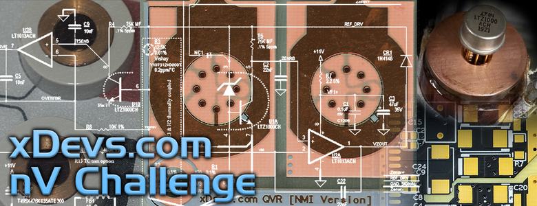
What is this Nanovolt Challenge?

Welcome to this friendly competition dedicated to building some nanovolt-grade hardware and analog designs! This public challenge dedicated for making your own open-source DC Voltage measurement device. Main audience is the electronic design engineers and metrology scientists, who have practical interests in performing very low level DC Voltage signal measurements (microvolt level and below).

Main goal of this contest is to show practical benefits of proposed nanovolt-capable design, not just theoretical possibility of such. There are many new ideas for low-level DC voltage measurements available with modern electronics and advance in digital and analog circuit designs, but very few are actually publicly discussed or demonstrated. This contest main goal is to promote such ideas and show openly what can be achieved in practical accomplished device.  :-/O

Challenge terms and rules

For international metrology community benefits it was decided that each project must comply with next conditions:

* Each submission entry must be based on actual physical design prototype and include design, measurement results and proof of operation.
* Submissions must be completed in 256 days term between September 2, 2021 23:59 EST and May 16, 2022 23:59 EST.
* All design information, including schematics, PCB files (not only Gerbers), libraries, simulation files and source code/firmware files must be publicly available under free to reuse license.
* Wiki or work log write-up about the project (at least 2000 words) with permission to publish it on xDevs.com site.
* There is no budget or component selection limit, as far as previous conditions about public design information is met.
* All designs must come with some sort of verification and performance results data. Noise, gain accuracy, thermal stability (+18 to +28 °C) and linearity parameters data is expected.
* Must not violate any commercial IP or 3rd-party license(s) (e.g. reverse-engineered commercial nano-voltmeter is not OK).
* All submissions must be written in English language.

Bonus point – if you were already working on nanovolt-related project before September 2, 2021, you can reuse any existing hardware, software or firmware and knowledge acquired, given that it should be published within submission entry and released for public as result.

Criteria for project relevance for acceptance

Proposed design must include hardware and software/firmware related to functionality of the unit. Additional calibration and used testing fixtures information is not required but very welcome. To focus design around somewhat common goal each of the nanovolt device entry should be able to perform next functionality to be accepted:

* Have local onboard power regulation. Single common DC (+9 to +24 VDC) or 110/220VAC mains input jack is expected.
* Provide DC Voltage measurement ranges ±100 µV or below and include ±1V and ±10VDC range.
* Have at least two user-accessible input channels for signal to be measured.
* Have low-thermal connection interface to minimize thermal EMF parasitic errors.
* Provide at least 5½-digit resolution for each reading.
* Ability to digitize input DC signal with resolution at least 10 nV and noise better than 30 nV peak to peak over at least 0.1-10 Hz bandwidth.
* Have autozero functionality to correct for static offsets.
* Have galvanic isolated analog front end, with isolation resistance to earth/chassis better than 10 GΩ.
* Device should have ADC (any type) integrated.
* Have good long-term stability and use ovenized DC voltage reference (LM399, LTZ1000 or LTFLU with oven).
* Provide RJ45 Ethernet and/or IEEE-488 GPIB interface for communications with external world / external equipment.
* 40W total input power budget (friendly to battery operation for sensitive experiments)
* Device should be fully operational as standalone device (e.g. no debuggers or external equipment attached to make it work).

Everything else is up to designers, no other limitations or restrictions. References with voodoo-slots, multi-layer PCBs, fancy OLED displays, Raspberry Pi controllers, gold-plated Titanium enclosures – all is welcome.

Compensation for winning project

Since reaching goals of the project are not easy nor simple additional motivation is provided for the best design award.

* Special version of xDevs.com QVR-A module with four of brand new Analog Devices ADR1000 ultra-low noise references.
* Calibration of QVR-A module on Josephson Junction Voltage Quantum Standard (once) with uncertainty below 0.1 ppm.


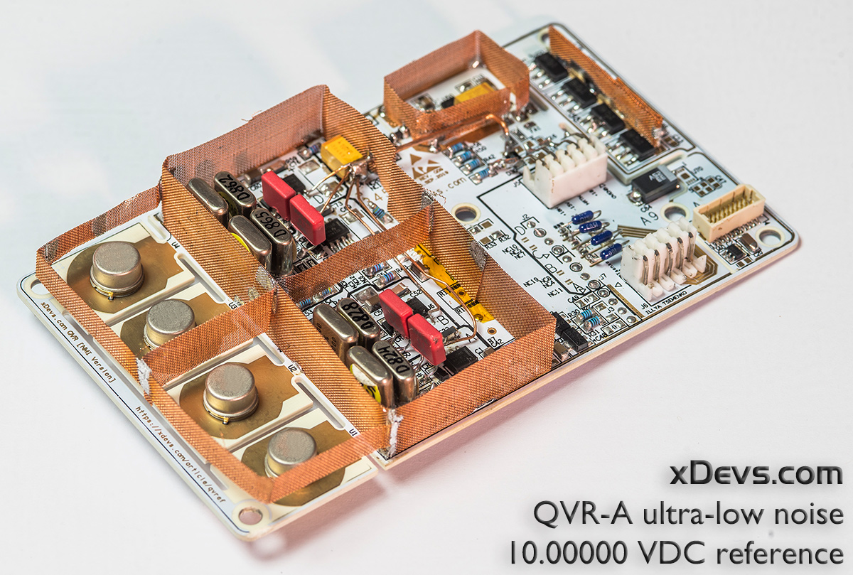
Reference will be packaged in custom rugged aluminum enclosure with low-thermal connectors and protected in hard-case shipping container.

Shipping cost of the QVR-A and JVS calibration will be covered by xDevs.com. Projects will be judged and carefully reviewed after challenge reach the deadline cutout. Final results and ranking will be provided on this page no later than June 16, 2022 23:59 EST. Reference and calibration will be shipped to winner no later than July 31, 2022.

Additional items and prizes might be added in future.

Full details about this challenge contest provided here. Instructions for project submissions are there as well.

Discussion and feedback also can be done in this thread.
« Last Edit: May 17, 2022, 04:14:07 am by TiN »
YouTube | Metrology IRC Chat room | Let's share T&M documentation? Upload! No upload limits for firmwares, photos, files.
 
The following users thanked this post: croma641, bck, jaromir, chuckb, ramon, Irv1n, macaba, I wanted a rude username, Trader

Offline MegaVolt

  • Frequent Contributor
  • **
  • Posts: 917
  • Country: by
Re: Nanovolt design challenge - build and show your own nV-meter in 256 days
« Reply #1 on: September 03, 2021, 10:00:25 am »
Make a Keithley 181 analog in 256 days.

This is a serious challenge...
 
The following users thanked this post: niner_007

Online Kleinstein

  • Super Contributor
  • ***
  • Posts: 14197
  • Country: de
Re: Nanovolt design challenge - build and show your own nV-meter in 256 days
« Reply #2 on: September 03, 2021, 12:37:09 pm »
The Keithley 181 would fail the criteria. Not sure it could measure at a speed to cover the 0.1 to 10 Hz range. This kind of needs at least some 20 readings per second, to really cover it more like 30 or 50 readings per second. Because of mains hum one would kind of need integration over full mains periods. So this would mean using 1 PLC, maybe 2 PLC with no time lost to AZ.
The point noise is a difficult one if it is meant as 30 nV_pp for 0.1 to 10 Hz BW, and not as allowing to measure 0.1 to 10 Hz BW and get the 30 nV_pp noise level at a lower speed.

With "only" the 5.5 digit range, I see no real need for a oven stabilized reference though. It is still easy if the LM399 is available.
 

Offline Psi

  • Super Contributor
  • ***
  • Posts: 9950
  • Country: nz
Re: Nanovolt design challenge - build and show your own nV-meter in 256 days
« Reply #3 on: September 03, 2021, 12:51:46 pm »
* All design information, including schematics, PCB files (not only Gerbers), libraries, simulation files and source code/firmware files must be publicly available under free to reuse license.

Do you mean a open source hardware license that allows free commercial use?

Are the participants going to see a company making and selling their exact design a year later  :-//

I'm not criticizing this, it's just important people know from the start.
It's pretty disheartening when you spend a year of your free time making something awesome for the community
and the next year your product is being sold in the 1000's with a high price tag by some company.

To be clear, this is a cool competition/design challenge and I'm 100% for it, it just need to be transparent on this issue.
« Last Edit: September 04, 2021, 02:06:37 am by Psi »
Greek letter 'Psi' (not Pounds per Square Inch)
 
The following users thanked this post: The Soulman

Offline ramon

  • Regular Contributor
  • *
  • Posts: 143
  • Country: tw
Re: Nanovolt design challenge - build and show your own nV-meter in 256 days
« Reply #4 on: September 03, 2021, 03:50:35 pm »
Thank you Tin for this challenge!

Wouldn't be great if someone provides for free something that is a hit (both technically and economically)?

Wonder if this open contest could translate into colleagues trying to contribute ideas to make something great that could not be possible if each one individually try to beat each other.

Unfortunately, I am not able to contribute any special skill into this task. So I will be just happy to watch how this develops ...

The terms and rules states that ALL must be publicly available, with granted permission to xDevs to publish it. This means to me that it is completely open. Anyone could make the device too, not just one company.

Success would mean that the next year the evil auction site will have tens of sellers selling the PCBs or assembled boards to make our own nanovoltmeter for less than the price of AoE book.

It's not the winning, it's the taking part. So they say!
 
The following users thanked this post: bck

Offline ramon

  • Regular Contributor
  • *
  • Posts: 143
  • Country: tw
Re: Nanovolt design challenge - build and show your own nV-meter in 256 days
« Reply #5 on: September 03, 2021, 04:05:40 pm »
Hey, I am reading the rules again and I think that It's super easy.

5½-digit, 100uv (10nV resolution):

Code: [Select]
+100.00
+ 99.99
+  0.00
- 99.99
-100.00

I have a few ICL7135 here, I think I can have some hack prepared next week.
 

Online The Soulman

  • Frequent Contributor
  • **
  • Posts: 949
  • Country: nl
  • The sky is the limit!
Re: Nanovolt design challenge - build and show your own nV-meter in 256 days
« Reply #6 on: September 03, 2021, 04:37:01 pm »
* Have local onboard power regulation. Single common DC (+9 to +24 VDC) or 110/220VAC mains input jack is expected.
* Provide DC Voltage measurement ranges ±100 µV or below and include ±1V and ±10VDC range.
* Have at least two user-accessible input channels for signal to be measured.
* Have low-thermal connection interface to minimize thermal EMF parasitic errors.
* Provide at least 5½-digit resolution for each reading.
* Ability to digitize input DC signal with resolution at least 10 nV and noise better than 30 nV peak to peak over at least 0.1-10 Hz bandwidth.
* Have autozero functionality to correct for static offsets.
* Have galvanic isolated analog front end, with isolation resistance to earth/chassis better than 10 GΩ.
* Device should have ADC (any type) integrated.
* Have good long-term stability and use ovenized DC voltage reference (LM399, LTZ1000 or LTFLU with oven).
* Provide RJ45 Ethernet and/or IEEE-488 GPIB interface for communications with external world / external equipment.
* 40W total input power budget (friendly to battery operation for sensitive experiments)
* Device should be fully operational as standalone device (e.g. no debuggers or external equipment attached to make it work).

Why 1 and 10Vdc? must they use the same front-end/connections?
Why Lan or GPIB? no opto isolated serial connection?
Why ovenized v-ref? There are plenty non-ovenized low tempco zeners (good enough for 6 digits) available?
Minimum two in-depended channels with own adc, multiplexed or manual switchable?
Minimum input impedance requirements??

Looks like fun, but a lot of work with a few unnecessary complications.
 
The following users thanked this post: nuclearcat

Offline dietert1

  • Super Contributor
  • ***
  • Posts: 2071
  • Country: br
    • CADT Homepage
Re: Nanovolt design challenge - build and show your own nV-meter in 256 days
« Reply #7 on: September 03, 2021, 04:57:20 pm »
...
I have a few ICL7135 here, I think I can have some hack prepared next week.
I think your table and that chip is considered 4 1/2.
Better way to go is an AD7177 or a TI ADS1263. Those have on-chip temperature sensors, so they can be made nV stable even without zeroing by a relay. I think a fairly easy challenge, build something like the HPM7177. There is one for sale in Germany right now and the design is open. Just add a variable gain front-end.

Regards, Dieter
 
The following users thanked this post: ramon

Offline guenthert

  • Frequent Contributor
  • **
  • Posts: 712
  • Country: de
Re: Nanovolt design challenge - build and show your own nV-meter in 256 days
« Reply #8 on: September 03, 2021, 05:17:39 pm »

Why 1 and 10Vdc? must they use the same front-end/connections?
Why Lan or GPIB? no opto isolated serial connection?
Why ovenized v-ref? There are plenty non-ovenized low tempco zeners (good enough for 6 digits) available?
Minimum two in-depended channels with own adc, multiplexed or manual switchable?
Minimum input impedance requirements??

Looks like fun, but a lot of work with a few unnecessary complications.

     Not that I'll be able to compete, but I was wondering the same.  It's easy enough to slap a RPi/Beagle Bone at the end for Ethernet or a AR488 in device mode for GPIB (for new devices? really?), once there is a serial connection, but why make it part of this challenge?

     And yes, instead of specifying an ovenized reference, I'd rather see some 120s / 24h drift specifications.

     Not sure why asking for a 1V and 10V range on a nanovoltmeter (the Keithley 181 has those and they are imho utterly useless as they i) use a different connector there and ii) performance is only mediocre).  I'd rather see a minimum safe input voltage (difference on input as well as common mode) specification.
« Last Edit: September 03, 2021, 05:30:10 pm by guenthert »
 

Online Kleinstein

  • Super Contributor
  • ***
  • Posts: 14197
  • Country: de
Re: Nanovolt design challenge - build and show your own nV-meter in 256 days
« Reply #9 on: September 03, 2021, 07:23:09 pm »
A 1 and 10 V range using the same reference and ADC  are nice sometimes, especially if there is enough resolution.
Requiring a 100 µV range is odd, as this would mean 1 nV resolution (if still 5 digits) - depending on the ADC resolution one may not even need a 1 mV range to get 10 nV resolution. Ok one could allways "cheat" in SW and arificially limit the range. I would guess a 20 V range instead of 10 V should be OK too.

The 1 and 10 V range may be good to test the reference drift. It would add a bit to the challenge if the 10 V need to work from the same terminals.

I would consider the front end the real challenge, the rest is more like easy.
 

Offline maxwell3e10

  • Frequent Contributor
  • **
  • Posts: 869
  • Country: us
Re: Nanovolt design challenge - build and show your own nV-meter in 256 days
« Reply #10 on: September 03, 2021, 07:52:02 pm »
So it's a bit better noise performance than HP 34420, which can do about 70 nVpp at 1NPLC and  30nVpp at 10NPLC.

30 nVpp in 0.1Hz to 10 Hz one can get with a single LT6018 op-amp (if datasheet is to be believed).

One needs to specify a source resistance or current noise level. Also long term gain and offset stability.
 

Offline 1audio

  • Frequent Contributor
  • **
  • Posts: 304
  • Country: us
Re: Nanovolt design challenge - build and show your own nV-meter in 256 days
« Reply #11 on: September 04, 2021, 04:21:24 am »
I got one of these https://quantasylum.com/collections/frontpage/products/qa351-uv-dc-voltmeter some time ago. Its actually pretty close to what is specified.  It does have really good (gigaOhm) isolation from the USB interface. The weakness are BNC input (I added a double banana jack) and the need for an input conditioner/gain to get deeper into the nanovolts. I have tried it between two precision references and its been quite stable. Its not a direct replacement as is for a nanovoltmeter but it suggests a pretty direct path.

One aspect I would suggest for this competition is using a USB interface. Easier possibly and you can get power from the interface and move the analysis off to a PC.
 

Offline TiNTopic starter

  • Super Contributor
  • ***
  • Posts: 4543
  • Country: ua
    • xDevs.com
Re: Nanovolt design challenge - build and show your own nV-meter in 256 days
« Reply #12 on: September 04, 2021, 05:12:07 pm »
Let's address questions.

Quote
Do you mean a open source hardware license that allows free commercial use?

Project should be fully open to benefit everyone. From my end I can only tell that there is no commercial or business interest from me in making or selling anything resulted from this challenge. But others, including author of design is welcome to start an enterprise and sell stuff. It is however niche market and would need serious invenstment to turn into business, so not something you can easily sell "in 1000's next year". Goal is to share the knowledge and educate new generation engineers about difficulty of low level voltage measurements. I'm going to design my own version of device as well (not competing in challenge  ;D).

Quote
I have a few ICL7135 here, I think I can have some hack prepared next week.

+100.00 uV to -100.00 uV was 4.5-digit indeed. I expect ADC side to be very easy/easy, comared to sensitive nV-frontend, where the main challenge is. The requirement to have ADC integrated in project is to rule out designs with just nV-preamplifier box connected to commercial DMM and calling it a day.

Quote
Why 1 and 10Vdc? must they use the same front-end/connections?
So you could quicky check if your DUT performing or what signal is there, before you switch to low voltage ranges (and overload them). Should use same input port (challenge about switching nV-type signals and 10V FS? ;) )

Quote
I'd rather see a minimum safe input voltage (difference on input as well as common mode) specification.
Well, consider 10V as minimum safe input voltage, meaning that nV frontend should not blow up when 10V applied to it (it does not have to be functional, obviously). You never connected 10V DC Voltage reference for opposite measurement in wrong polarity before, having 20V across nV-input, instead of few uV/mV?  :-BROKE
No need to have CAT rating or safety certification for design, it's for laboratory bench use in baby care gloves anyway :)

Quote
Why Lan or GPIB? no opto isolated serial connection?
No serial or USB or SPI/I2C so you could easily integrate meter into bigger experiments with commercial gear.

Quote
It's easy enough to slap a RPi/Beagle Bone at the end for Ethernet or a AR488 in device mode for GPIB (for new devices? really?), once there is a serial connection, but why make it part of this challenge?
Ease of integration was the reason for LAN/GPIB. LAN(VXI) and GPIB are existing infrastructure and allow paralleling many devices without effort. Serial/optical/USB not so much as there is no single standard way and hardware for multi-device with those interfaces. They are fine for one, maybe two devices, but what if you want 8?

Quote
Why ovenized v-ref? There are plenty non-ovenized low tempco zeners (good enough for 6 digits) available?
It's not about tempco, but about long-term stability, so device should not need frequent recalibration.

Quote
And yes, instead of specifying an ovenized reference, I'd rather see some 120s / 24h drift specifications.
No rules or hard specifications here, that would be points for judging from actual designs. Using ovenized reference by default will already make it very good and limited by nV-frontend stability. ;)

Quote
Minimum two in-depended channels with own adc, multiplexed or manual switchable?
Input channels can be switched at the front-end (think as integrated nV-multiplexer? Can be more than 2 channels too).

Quote
Minimum input impedance requirements??

Quote
One needs to specify a source resistance or current noise level. Also long term gain and offset stability.
These are up to designer. Idea is to have and demo performance of different designs with possible different use cases, not some fully specified and polished commercial-grade instrument being built in 256 days.  :-DMM

Quote
I think a fairly easy challenge, build something like the HPM7177.
HPM7177 was motivational for this idea, yes. But with more focus on low level voltage signals, rather than ultimate stability.


« Last Edit: September 04, 2021, 05:25:03 pm by TiN »
YouTube | Metrology IRC Chat room | Let's share T&M documentation? Upload! No upload limits for firmwares, photos, files.
 
The following users thanked this post: bck

Offline armandine2

  • Frequent Contributor
  • **
  • Posts: 600
  • Country: gb
Re: Nanovolt design challenge - build and show your own nV-meter in 256 days
« Reply #13 on: September 04, 2021, 08:53:52 pm »
Let's address questions.
HPM7177 was motivational for this idea, yes.

when I google "hpm7177 open source" something comes up - whether in 256 days from now I'll know much more is doubtful? But from to doubt to to know is the usual way.
Funny, the things you have the hardest time parting with are the things you need the least - Bob Dylan
 

Offline MegaVolt

  • Frequent Contributor
  • **
  • Posts: 917
  • Country: by
Re: Nanovolt design challenge - build and show your own nV-meter in 256 days
« Reply #14 on: September 04, 2021, 09:02:47 pm »
Goal is to share the knowledge and educate new generation engineers about difficulty of low level voltage measurements.
...
The requirement to have ADC integrated in project is to rule out designs with just nV-preamplifier box connected to commercial DMM and calling it a day.
A good amplifier connected to a typical multimeter, in my opinion, will allow to better show the peculiarities of nanovolts and will not have to spend effort on the software interface and ADC.
 
The following users thanked this post: egonotto

Offline TiNTopic starter

  • Super Contributor
  • ***
  • Posts: 4543
  • Country: ua
    • xDevs.com
Re: Nanovolt design challenge - build and show your own nV-meter in 256 days
« Reply #15 on: September 04, 2021, 10:36:02 pm »
It's about system design as well. It's easier to build nV-amplifier, enclose it in magical thermal vacuum chamber and measure a copper short circuit with sub-nV noise.
Completely different story to integrate same amplifier in same box with digital and power supply and then battle for thermal inbalances, noise pickup, magnetic interferences and switching problems, etc.  :-/O
YouTube | Metrology IRC Chat room | Let's share T&M documentation? Upload! No upload limits for firmwares, photos, files.
 
The following users thanked this post: egonotto

Offline ramon

  • Regular Contributor
  • *
  • Posts: 143
  • Country: tw
Re: Nanovolt design challenge - build and show your own nV-meter in 256 days
« Reply #16 on: September 05, 2021, 12:33:40 am »
Goal is to share the knowledge and educate new generation engineers about difficulty of low level voltage measurements. I'm going to design my own version of device as well (not competing in challenge  ;D).

Will that project be open?

Wouldn't be easier if you just post a thread with your requirements and goals and let everyone participate to provide feedback and at the same time being able to reproduce the design and test it with their own gear?

You can divide the project into sections (like connectors area, input stage, ADC, computer interface, ...). And let everyone participate and build their own version. As everyone has its own bias regarding design requirements so this will allow everyone to 'fork' the design into whatever they prefer.  There are many different areas of design that require different skills, so everyone can be mentor or apprentice.
 

Offline TiNTopic starter

  • Super Contributor
  • ***
  • Posts: 4543
  • Country: ua
    • xDevs.com
Re: Nanovolt design challenge - build and show your own nV-meter in 256 days
« Reply #17 on: September 05, 2021, 01:05:03 am »
I think contest challenge is more fun with some additional motivation and much less restrictions for requirements/particular design goals.
I'll also be using EM A10 commercial amplifier, so not much of actual nV-design will be done for my device.
« Last Edit: September 05, 2021, 01:14:54 am by TiN »
YouTube | Metrology IRC Chat room | Let's share T&M documentation? Upload! No upload limits for firmwares, photos, files.
 

Offline ramon

  • Regular Contributor
  • *
  • Posts: 143
  • Country: tw
Re: Nanovolt design challenge - build and show your own nV-meter in 256 days
« Reply #18 on: September 05, 2021, 01:14:53 am »
Let's address questions.
Quote
Why Lan or GPIB? no opto isolated serial connection?
No serial or USB or SPI/I2C so you could easily integrate meter into bigger experiments with commercial gear.
...
Ease of integration was the reason for LAN/GPIB. LAN(VXI) and GPIB are existing infrastructure and allow paralleling many devices without effort. Serial/optical/USB not so much as there is no single standard way and hardware for multi-device with those interfaces. They are fine for one, maybe two devices, but what if you want 8?

Your have very strong prejudice against RS232 and all of your statements are just plainly wrong.

There are plenty of multiple RS232 port interfaces for just the price of a single passive GPIB cable.

Being able to control several devices in parallel is not a protocol or transport issue, it is a control/system issue.

It can be done. RS232 has been in the telecommunication industry for many decades and you can parallel AND synchronize with as many systems as you want. Not to mention that it is simple, easy to implement, cheap, reliable, and has complete documentation available ... to name a few.

But I don't want to start any war. It is completely ok for me. To meet your requirements I plan to use a nice and cheap RS232-to-LAN (RJ45) adapter.  ;)
 
The following users thanked this post: Andreas

Offline Psi

  • Super Contributor
  • ***
  • Posts: 9950
  • Country: nz
Re: Nanovolt design challenge - build and show your own nV-meter in 256 days
« Reply #19 on: September 05, 2021, 03:49:09 am »
Quote
Do you mean a open source hardware license that allows free commercial use?
Project should be fully open to benefit everyone. From my end I can only tell that there is no commercial or business interest from me in making or selling anything resulted from this challenge.
:-+
Greek letter 'Psi' (not Pounds per Square Inch)
 

Offline dietert1

  • Super Contributor
  • ***
  • Posts: 2071
  • Country: br
    • CADT Homepage
Re: Nanovolt design challenge - build and show your own nV-meter in 256 days
« Reply #20 on: September 05, 2021, 06:13:56 am »
When TiN writes integration he means automation and wants to make it appear more "professional". But there is no mention of error handling, selftest or ACAL capabilities, nor any incentive for teamwork. Nothing but tinkering.
We'll see whether an open discussion like the one branadic initiated or TiNs challenge will produce something. From branadics thread i learned that the ADS126x is better than the ADS 1256 i recommended before: https://www.eevblog.com/forum/metrology/scannermultiplexers-for-voltage-references/msg3474342/#msg3474342. And from the HPM7177 documents and M. Reps' youtube video i learned we should have the ADC, its reference and its front end in a TEC oven.

Regards, Dieter
 
The following users thanked this post: ramon

Online tszaboo

  • Super Contributor
  • ***
  • Posts: 7388
  • Country: nl
  • Current job: ATEX product design
Re: Nanovolt design challenge - build and show your own nV-meter in 256 days
« Reply #21 on: September 05, 2021, 08:40:39 am »
To be honest, while at first it looked interesting, the more I read into the post, the more I decided that I couldn't be bothered to make this. Some of the requirements feel just a bit over the top, which would make this from an interesting design challenge to a nightmare.
Ethernet: nope, that means i probably have to spend more time doing linux kernel panic hard faults checking than designing the AFE. Also it pretty much restricts you to work with a single board computer. If you want to automate something, I give you a serial interface, or serial over USB, BOYD and have fun with that.
GPIB: Even worse. Restricts you for boards with plenty of GPIO and it is really high speed. And once again, I want to write as little code as possible.
Ovenized reference: Why? I can select a reference from the top of my head, that would provide this ~4.5 digit accuracy and it would do that for a very long time. And it would output 5V or something that the ADC uses, and the MF ships me one for free if I ask nicely. Instead, I'm supposed to spend something like 100EUR or more getting the REF and Vishay resistors, and not just that, but spend considerable amount of time verifying the characteristics of it. I don't even have the test setup at home to make such measurements. And I'm half sure that the ref wouldn't even be the limiting component in this AFE.
 

Online 2N3055

  • Super Contributor
  • ***
  • Posts: 6650
  • Country: hr
Re: Nanovolt design challenge - build and show your own nV-meter in 256 days
« Reply #22 on: September 05, 2021, 10:01:44 am »
I think contest challenge is more fun with some additional motivation and much less restrictions for requirements/particular design goals.
I'll also be using EM A10 commercial amplifier, so not much of actual nV-design will be done for my device.

I hugely support your initiative to develop an open source instrument for nV measurements, making this kind of measurements more accessible to more people.
But, despite huge respect I have for you and your immense Voltnuting acumen, i must disagree with you on many points.

What you wrote here means that you, for instance, won't be doing ANYTHING technically related to challenge of measuring nano Volts.
Nanovolt measuring challenge is all about device/DUT interconnect, front end , guarding and physical package of all that.

Even if you add A/D converter (that does have some benefits to be included in a device), then only protocol for data out should be exactly RS232 UART. That is dead simple to implement and is well standardized and common on T&M devices...Simple to galvanically isolate too...
And very simple to debug while development.
Ethernet with TCP/IP requires a full computer with protocol stack. That can be added later as an optional thing. You could use RaspberyPi for that, or anything really.

Nanovolt meter should be simple headless design, a box that receives nanovolt on one side and spews RS232 messages on the other. That makes digital side an A/D converter and  a MCU, even an Atmel Mega or equivalent device will do. Simple. Maybe few housekeeping messages. Those can even be SCPI compatible, because it can be easily implemented for those few simple commends.  If you insist on Ethernet, there things like X-port that convert serial UART to Ethernet. Very simple.

And then you can have front panel that has UI that speaks with measurement module. All instruments have that design.
If you take MCU that has 2 UARTs you can speak with front panel and outside world at the same time.

Making it modular something like that also means that different people (that have different skillsets) develop best front end and there can be simple 7-segment display module and also a graphic screen display module if someone wants that...

As for 10 V ranges, since this is not to be high grade meteorological instrument with 8.5 digit accuracy, why would you spend months adding something like that and potentially compromising design, when for cursory check you can use a separate 50 € handheld device?  That everybody already have.

Input should be made to survive 25-30 V P-P constant and to survive basic ESD events.

As for ovenized reference,  I don't mind, price difference is not much. But very stable ovenized reference won't have much correlation on stability of instrument. I expect other things to drift much, much more than reference. If anything, maybe opting for low power reference to make temperature gradients in sensitive analog module less?
Or whole analog module made on alu substrate board and ovenized ? In which case heated reference is not so much a problem...

Cheapest way to do nanovolt measurements today is to, exactly like you, buy EM Electronics amplifier and connect it to your bench meter.
If community endeavours to such a big task, frankly, there must be some benefit from it: either sub 200€ price (so benefit is being more affordable) or some advanced features, which can be very good analog performance (very hard to do) or maybe if a modular approach is adopted, fact that you can for instance only use front end module  and use it only as data acquisition module and pull data directly to PC with Python code or Scilab/Octave/Mathlab.  Or use of module integrated as a part of a micro ohm meter, or whatever you think off..

Best,
« Last Edit: September 05, 2021, 10:05:48 am by 2N3055 »
 
The following users thanked this post: The Soulman

Offline ramon

  • Regular Contributor
  • *
  • Posts: 143
  • Country: tw
Re: Nanovolt design challenge - build and show your own nV-meter in 256 days
« Reply #23 on: September 05, 2021, 10:29:28 am »
My solution for the PC interface is cheap ($10-20) and completely hassle free. No programming, no driver needed, no high speed CPU or SBC needed. The simplicity of rs232 with an rj45 connector.  Google: "usr-k5", "usr-k7", "usr-tcp232-s2".

About the ovenized reference, here I agree with Tin about having at least a LM399. It is not too expensive, not so difficult to buy, doesn't require too many expensive extra components, and its long term performance is know. (Too noisy, is maybe the only issue)

But, yes, you are rigth that many 5 digits and half meters have been done with lt1027, lt1021 or many other references. I have seven lt1021bcn8-7 (the version with 7 volts output for maximum long term stability) in a drawer. I was surprised about the stability and low noise when I tested one sample. Don't know if TIN would accept them inside an oven.
 
The following users thanked this post: I wanted a rude username

Offline jaromir

  • Supporter
  • ****
  • Posts: 338
  • Country: sk
Re: Nanovolt design challenge - build and show your own nV-meter in 256 days
« Reply #24 on: September 05, 2021, 03:16:19 pm »
Thank you TiN.
I like this contest very much. Yes, it's got non-trivial requirements, but that is a part of the game. :-+
 
The following users thanked this post: TiN

Offline TiNTopic starter

  • Super Contributor
  • ***
  • Posts: 4543
  • Country: ua
    • xDevs.com
Re: Nanovolt design challenge - build and show your own nV-meter in 256 days
« Reply #25 on: September 05, 2021, 04:44:36 pm »
Quote
What you wrote here means that you, for instance, won't be doing ANYTHING technically related to challenge of measuring nano Volts.
Nanovolt measuring challenge is all about device/DUT interconnect, front end, guarding and physical package of all that.
Sorry, but buying and using EM amplifier does not magically resolve all nV issues by itself. You still must do proper isothermal interconnect, power delivery and physical package. Otherwise you will get very poor (but low noise, yes!) thermometer of your lab.  ^-^

Quote
Nanovolt meter should be simple headless design, a box that receives nanovolt on one side and spews RS232 messages on the other. That makes digital side an A/D converter and  a MCU, even an Atmel Mega or equivalent device will do. Simple. Maybe few housekeeping messages.
That also means that experimenter must find the host with RS232 to UART hardware, setup environment for it, program code to talk, debug whatever speed/stop bits/inversion, timings etc. instead of simply connecting equipment and reading data. I don't say RS232 cannot be done, it can. But not in this challenge.

Quote
Ethernet: nope, that means i probably have to spend more time doing Linux kernel panic hard faults checking than designing the AFE.
In 10 years doing this, never had to look into any kernel panics related to Ethernet or GPIB instruments.  :-//

Quote
That is dead simple to implement and is well standardized and common on T&M devices
Yet still many even commercial instruments have own tricks with RS232 implementations and need messing around with settings/drivers/etc. to make work with ubiquitous Raspberry Pi or alike. In my lab I always curse instruments which only have RS232 and nothing else (so far it is only Arroyo TEC controllers and Lakeshore 331, everything else is on LAN or GPIB networks).
Let's make it personal bias against RS232 on instruments and be done with it  :D.

To be clear, UART, I2C or SPI are totally OK to be used between AFE isolated section and outguard host interfacing external world.

Quote
Ethernet with TCP/IP requires a full computer with protocol stack. That can be added later as an optional thing. You could use Raspberry Pi for that, or anything really.
Quote
If you insist on Ethernet, there things like X-port that convert serial UART to Ethernet. Very simple.
So is it requiring full computer, or its very simple with converter? :) Ethernet or GPIB, this is the way. If interface upsets someone enough not to participate, well, sorry about that, nothing can be done.  :-//

Quote
Making it modular something like that also means that different people (that have different skillsets) develop best front end and there can be simple 7-segment display module and also a graphic screen display module if someone wants that...
That would be great. As challenge terms outline, team submissions are totally OK and very welcome. There is no requirement to have everything on same PCB/same enclosure with nV AFE, only the requirement not to have external equipment (e.g. power supplies or host computers/debuggers connected to have setup working ;)

Quote
Instead, I'm supposed to spend something like 100EUR or more getting the REF and Vishay resistors, and not just that, but spend considerable amount of time verifying the characteristics of it
.
Hm, LM399AH $17.4 USD for reference + few PTF56 15ppm/K resistors ($few) + opamp ($few). I don't see what else to go for 100 EUR to integrate ovenized ref? Also it's not much you can mess up with LM399A design, it's already all integrated and gives good performance without spending months to verify it (which you might need to do for many of the non-ovenized bandgap zeners).

« Last Edit: September 05, 2021, 04:51:37 pm by TiN »
YouTube | Metrology IRC Chat room | Let's share T&M documentation? Upload! No upload limits for firmwares, photos, files.
 

Offline guenthert

  • Frequent Contributor
  • **
  • Posts: 712
  • Country: de
Re: Nanovolt design challenge - build and show your own nV-meter in 256 days
« Reply #26 on: September 05, 2021, 05:13:58 pm »
     I think some of the, er, rather strong opinions come from a misunderstanding.  The challenge here is to create a more-or-less well specified device in a given time frame (but no given price range *), not a solution to the problem of how best (**) measure voltages in the nanovolt range (shouldn't it then be in the projects sections, rather than in metrology?).  Accept the challenge or move on, no need for harsh feelings.


*) hence I don't quite understand the concern that someone would commercialize it.
**) pick a meaning of best here
 
The following users thanked this post: TiN, 2N3055

Online 2N3055

  • Super Contributor
  • ***
  • Posts: 6650
  • Country: hr
Re: Nanovolt design challenge - build and show your own nV-meter in 256 days
« Reply #27 on: September 05, 2021, 05:31:14 pm »

I personally prefer Ethernet and don't like GPIB. So there are the biases. I still have GPIB adapter, because some of my devices have it. I use what I have.

But as many times as you keep repeating it is not going to make it true. UART +RS2323 electrical interface is the simplest, most standard and easiest serial interface to be implemented.
You set speed and coding (with 8 bit no parity practically being the norm for 20 years) and your good to go.
There are no "alternative" or "trick" with any RS232 devices. It simply works, and parsing of the strings is all the work.
And speaking with serial ports is so trivial from any software, that I won't even talk about that.
Saying Ethernet TCP/IP is simpler is simply not true.
I know, as I have been developing stuff on all kinds of interfaces for 30+ years.  UART is simplest to develop and to program for. It is slow but for this purpose fast enough.

No need to be snarky either. I try not to speak up if I don't know what I'm talking about. X-Port IS a Linux computer, a very minimal one.
Look it up. It is simple because if you use X-port, it simply serves as serial to TCP/IP gateway. It can expose a port so you simply establish a socket to it, and speak same strings as on serial port.  Which makes it so you can decide to implement RS232 only or drop 50€ and have TCP/IP. Or connect RS232 to Raspberry PI via UART and make software for that.

Look, it is simple.

You posted this as YOUR challenge.  You came up with rules that appear heavily slanted towards something you already have been working on and in way you think is right and what is good for you.  Me and few other here voiced opinions that it would be more beneficial to community to make something more generic and focused in such a way to spend most of the energy on important "nanovolt" part. Few of us have found some of your requirements unnecessary or not instrumental to core nanovoltmeter requirements.
I spoke up, you don't like it, that's fine. I won't be repeating or interfere anymore. It is your show.

I also won't be participating, because I would do it  either for the good of community, or would make a device that fits my specific requirement, not some other person that have different needs them myself. And I don't have time to participate in this as a pissing contest, just to show off.

So good luck to everybody and will following to see what interesting ideas will be developing here.

Best,
 
The following users thanked this post: TiN, BrianHG, souldevelop, MaxZ

Online bdunham7

  • Super Contributor
  • ***
  • Posts: 7854
  • Country: us
Re: Nanovolt design challenge - build and show your own nV-meter in 256 days
« Reply #28 on: September 05, 2021, 07:05:09 pm »
And I'm half sure that the ref wouldn't even be the limiting component in this AFE.

I suspect (and hope) that the winner of this contest will actually post specs that would necessitate at least a decent select LM399, although perhaps not in the lowest range.  I'm not going to be entering in the contest either, but I'll admit that the actual reasons are that I'm not clever enough and I don't have good enough equipment to test/verify such a device--not that I'm too busy or don't think the project is worthwhile.
A 3.5 digit 4.5 digit 5 digit 5.5 digit 6.5 digit 7.5 digit DMM is good enough for most people.
 

Online Kleinstein

  • Super Contributor
  • ***
  • Posts: 14197
  • Country: de
Re: Nanovolt design challenge - build and show your own nV-meter in 256 days
« Reply #29 on: September 05, 2021, 07:41:44 pm »
Testing and verifying could be hard, at least to the full performance levels. Some tests (e.g. noise) are easy, but some others (e.g. INL) are quite tricky, though testing to the 5 digit level should be a bit simpler than 7 digit level. If really needed chances are one could find a fellow to do some of the tests.

For the 5 digit level one could for sure get away with less than an LM399 and for a more lower power version this may also be a good idea. There is always the option to have a separate working ref for the ADC and the LM399 mainly for a check. The Keithley 2001 and AFAIK also the 2182 use this way. The interface is something to worry last, though for testing it help to have a interface to the computer in some way already relatively early.
Chances are many attempts end up with a partially (e.g. a bit too much noise or drift) working low frequency amplifier.
 
The following users thanked this post: TiN, 2N3055

Online macaba

  • Regular Contributor
  • *
  • Posts: 205
  • Country: gb
Re: Nanovolt design challenge - build and show your own nV-meter in 256 days
« Reply #30 on: September 05, 2021, 08:21:31 pm »
Thank you TiN.
I like this contest very much. Yes, it's got non-trivial requirements, but that is a part of the game. :-+

I concur, thanks TiN. It’s your contest and you’ve fronted the first (and maybe only) prize so you set the requirements.

I’ve been simulating various front ends to get a feel for the analog wizardry required, I’m very much looking forwards to seeing what comes out in 250+ days!


Offline maxwell3e10

  • Frequent Contributor
  • **
  • Posts: 869
  • Country: us
Re: Nanovolt design challenge - build and show your own nV-meter in 256 days
« Reply #31 on: September 06, 2021, 09:18:30 am »
The way the rules are currently written it will motivate one toward a gold-plated design, both figuratively and literally, especially if the goal is to win the gold-plated prize. But to me a more interesting challenge is to have the simplest design that still meets the metrics and gets maybe within 20% of the gold-plated approach at 10% of the cost.

From this point of view it maybe interesting to use an ADC evaluation board or another low-cost DAQ as the back-end of the system. That would minimize the relatively trivial design aspects and allow others to duplicate the system with minimal effort.

For example ADS125H02 seems like an interesting 24-bit ADC that can make a decent DVM by itself. It has two channels with +/-15 V maximum input range, 2 ppm INL and adjustable gain. There is an evaluation board ADS125H02EVM for $99. While it does not provide galvanic isolation, it is laid out so it can be split and isolated with addition of a few parts.
 
The following users thanked this post: 2N3055, ramon, MegaVolt, dietert1

Offline EEVblog

  • Administrator
  • *****
  • Posts: 37740
  • Country: au
    • EEVblog
Re: Nanovolt design challenge - build and show your own nV-meter in 256 days
« Reply #32 on: September 06, 2021, 10:46:38 am »
The way the rules are currently written it will motivate one toward a gold-plated design, both figuratively and literally, especially if the goal is to win the gold-plated prize. But to me a more interesting challenge is to have the simplest design that still meets the metrics and gets maybe within 20% of the gold-plated approach at 10% of the cost.

A "best bang per buck" award?
 

Offline iMo

  • Super Contributor
  • ***
  • Posts: 4784
  • Country: pm
  • It's important to try new things..
Re: Nanovolt design challenge - build and show your own nV-meter in 256 days
« Reply #33 on: September 07, 2021, 11:23:55 am »
..
For example ADS125H02 seems like an interesting 24-bit ADC that can make a decent DVM by itself. It has two channels with +/-15 V maximum input range, 2 ppm INL and adjustable gain.
..
While reading its DS it looks to me as it is a no-brainer complete voltmeter with 6+ digits resolution. Any experience with the chip? How it compares with the DIY MS_ADCs here?
 

Online Kleinstein

  • Super Contributor
  • ***
  • Posts: 14197
  • Country: de
Re: Nanovolt design challenge - build and show your own nV-meter in 256 days
« Reply #34 on: September 07, 2021, 12:26:12 pm »
The ADS125H looks interesting for a simple DVM. One slight difficulty may be the common mode range: with one side at ground the useful input range seems to be smaller. It may still be just enough for 10 V. 
The noise is OK for a 6 digit meter, roughtly comparable to the 34401 or Keithly 2000 (though the conparison is not so easy as the input is contineously sampled (the K2000 / 34401 spend half the time for auto zero) and depending on the filter consecutive readings are not independent.
The INL looks quite good, though it can be worse when 1 side is fixed at GND.
My DIY MS-ADC is lower noise (about a factor of 5) and hopefully better INL, but lower maximum speed. However it is more effort and a bit overkill for a nV meter. I may still be tempted to start from there. The ADS125H is also my short list for the ADC.
Most SD ADC have the advantage of sampling the input all the time and this way getting a lower bandwidth for the input and input amplifier than a classical AZ clycle with an MS ADC. With input noise as the critical points, one would not want to start with twice the effective BW (as with many older DMMs).
 
The following users thanked this post: iMo

Offline iMo

  • Super Contributor
  • ***
  • Posts: 4784
  • Country: pm
  • It's important to try new things..
Re: Nanovolt design challenge - build and show your own nV-meter in 256 days
« Reply #35 on: September 07, 2021, 02:05:22 pm »
The ADS125H looks interesting for a simple DVM. One slight difficulty may be the common mode range: with one side at ground the useful input range seems to be smaller. It may still be just enough for 10 V. 
..
According to the DS the single ended input range is +/- 15.5V with +/-18V AFE power supply.
PS: with more traditional +/- 15V analog power source the single ended input range will be +/-12.5V, imho.
There is also a "PGA threshold" 2V below analog power lines (it sets a bit indicating the adc reading is off the range).
« Last Edit: September 07, 2021, 04:16:38 pm by imo »
 

Offline TiNTopic starter

  • Super Contributor
  • ***
  • Posts: 4543
  • Country: ua
    • xDevs.com
Re: Nanovolt design challenge - build and show your own nV-meter in 256 days
« Reply #36 on: September 14, 2021, 02:57:50 am »
So far I had something like this in mind as a concept for this project.  :)

YouTube | Metrology IRC Chat room | Let's share T&M documentation? Upload! No upload limits for firmwares, photos, files.
 

Online Kleinstein

  • Super Contributor
  • ***
  • Posts: 14197
  • Country: de
Re: Nanovolt design challenge - build and show your own nV-meter in 256 days
« Reply #37 on: September 14, 2021, 06:58:20 am »
I don't think a nV meter would need AC coupling, at least not for the main path.
I would expect the low noise nV preamplifier output to also go though the main amplifier for the other ranges. This way less (maybe even none) gain switching in the nV preamplifier is needed. Chances are the SD ADC would need an extra divider for the 10 V (or similar) range, unless one uses the ADS125H  .

The input protection is a slightly tricky part. At least the version I have in my mind (and use with my voltmeter) can use the protection also as part of the input switching.  So protection and the low thermal MUX may be combined.
 

Online macaba

  • Regular Contributor
  • *
  • Posts: 205
  • Country: gb
Re: Nanovolt design challenge - build and show your own nV-meter in 256 days
« Reply #38 on: September 14, 2021, 08:31:59 am »
I was also thinking switchable AC coupling so I like that, it allows for many more use cases. It’s probably practically part of the low thermal block, using the same relays and isothermal area.

You won’t (and IMO shouldn’t) be able to chop the 1/f noise of the AC coupling. So it’ll be something like 30nVpp for the DC coupling and some higher value for the AC coupling. (and that’s ok for the AC coupling use cases)
« Last Edit: September 14, 2021, 08:34:30 am by macaba »
 

Offline bobAk

  • Contributor
  • Posts: 39
  • Country: fr
Re: Nanovolt design challenge - build and show your own nV-meter in 256 days
« Reply #39 on: September 14, 2021, 11:18:27 am »
Hi everybody. I have a couple of questions. Looking at Tin proposal, it turns out that we will not be engaged in the development of the nanovoltmeter heart? In fact, this is a lego constructor and the result of the challenge depends on whether there is an nv amplifier module on the table or not. Why does a nanovoltmeter need a 24-bit ADC? If its capabilities are redundant.
 
The following users thanked this post: Mickle T., bsw_m, justanothername

Offline bsw_m

  • Regular Contributor
  • *
  • Posts: 241
  • Country: by
Re: Nanovolt design challenge - build and show your own nV-meter in 256 days
« Reply #40 on: September 14, 2021, 11:48:08 am »
So far I had something like this in mind as a concept for this project.  :)
What can I say. Good luck building a nanovoltmeter using this concept.  ;)
 

Offline TiNTopic starter

  • Super Contributor
  • ***
  • Posts: 4543
  • Country: ua
    • xDevs.com
Re: Nanovolt design challenge - build and show your own nV-meter in 256 days
« Reply #41 on: September 14, 2021, 11:54:34 am »
To be clear, I'm not competing in any shape or form with this. And may do own nV amplifier block instead of A23. Perhaps better idea to create separate thread in Projects about this, instead of OT this one about contest.

Kleinstein is right, realized that nV amp output should go to x5 gain instead of a\d mux directly.
YouTube | Metrology IRC Chat room | Let's share T&M documentation? Upload! No upload limits for firmwares, photos, files.
 

Offline justanothername

  • Regular Contributor
  • *
  • Posts: 143
  • Country: at
Re: Nanovolt design challenge - build and show your own nV-meter in 256 days
« Reply #42 on: September 14, 2021, 01:08:21 pm »
I would consider the front end the real challenge, the rest is more like easy.

The rest is time consuming. I'd really like to have the time to make a nice low cost and compensated front end (including ADC maybe), not to program a complete instrument.
I guess this challenge is more for people that already have a design in the drawer. So if the rules are refined towards the essentials, I'm in.
 
The following users thanked this post: chickenHeadKnob

Offline dietert1

  • Super Contributor
  • ***
  • Posts: 2071
  • Country: br
    • CADT Homepage
Re: Nanovolt design challenge - build and show your own nV-meter in 256 days
« Reply #43 on: September 15, 2021, 10:47:50 am »
Yes, can we define meaningful requirements for input protection? For low noise input protection resistors are impractical. How about a pair of JFETs for bipolar current limiting. I found some with copper leads that support +/- 40 V at a 2 mA current max. I think that would be a good start.
Will put them into a piece of aluminum tube for lowest thermal EMF. That part can also be used to replace the 2x 51K resistors in the frontend of a 3457A used for voltage reference monitoring.

Regards, Dieter
 

Offline MegaVolt

  • Frequent Contributor
  • **
  • Posts: 917
  • Country: by
Re: Nanovolt design challenge - build and show your own nV-meter in 256 days
« Reply #44 on: September 15, 2021, 10:51:51 am »
I found some with copper leads that support +/- 40 V at a 2 mA current max.
Are these items available? Can you tell me their name?
 

Online Kleinstein

  • Super Contributor
  • ***
  • Posts: 14197
  • Country: de
Re: Nanovolt design challenge - build and show your own nV-meter in 256 days
« Reply #45 on: September 15, 2021, 11:28:53 am »
I would consider protection similar to the Keithley2001, 2002 and 2182: so 2 back to back MOSFETs with a photovoltaic optocoupler to drive the gates. That is a bit like doing a photomos solid state relay from discrete parts. A second optocoupler can turn off the FETs relatively fast, if the ouput side voltage gets too high.
The separate part solution has the advantage that the heat producing part (the PV opto-coupler) can be a bit away from the rest.

The good point here is that one can use the protection also as switches. They are more like switches that also act as protection.

As a simple resistor replacement with lower noise one could use depl. mode MOSFETs. They work kind of similar to the JFETs, but are avilable also for higher voltages (like 800 V). Not sure if they offer copper leads (the higher power ones may).
 

Offline ferret_guy

  • Newbie
  • Posts: 8
  • Country: us
Re: Nanovolt design challenge - build and show your own nV-meter in 256 days
« Reply #46 on: September 15, 2021, 01:51:19 pm »
I reached out to EM electronics about the pricing of the A23 and they provided the attached price list.

Some highlights:

Device    Equivalent Noise Resistance    Price
DC Picovoltmeter Model P13a    0.25Ω    £9,500
DC Nanovolt Amplifier Model A10    20Ω    £695
DC Nanovolt Amplifier Model A20a    10Ω    £4,300
DC Nanovolt Amplifier Model A22    150Ω    £295
DC Nanovolt Amplifier Model A23    25Ω    £360
« Last Edit: September 24, 2021, 04:24:51 pm by ferret_guy »
 
The following users thanked this post: egonotto, Vgkid, splin, doktor pyta, 2N3055, MiDi, ch_scr, MegaVolt

Offline maxwell3e10

  • Frequent Contributor
  • **
  • Posts: 869
  • Country: us
Re: Nanovolt design challenge - build and show your own nV-meter in 256 days
« Reply #47 on: September 15, 2021, 03:30:21 pm »
Thanks. Does anyone know who is involved in EM electronics these days? Speaking on the phone with them a few years ago it seemed to be the old guard (very knowledgeable!). Even though I don't really need one of these modules now, I've been tempted to get one in case they fold in a few years.
 

Offline TiNTopic starter

  • Super Contributor
  • ***
  • Posts: 4543
  • Country: ua
    • xDevs.com
Re: Nanovolt design challenge - build and show your own nV-meter in 256 days
« Reply #48 on: September 20, 2021, 11:38:01 pm »
Heh, Dave and Chris had great fun on the Amp Hour #558 discussing this contest and volt-nuttery OCD.   :popcorn:
YouTube | Metrology IRC Chat room | Let's share T&M documentation? Upload! No upload limits for firmwares, photos, files.
 
The following users thanked this post: doktor pyta

Offline ferret_guy

  • Newbie
  • Posts: 8
  • Country: us
Re: Nanovolt design challenge - build and show your own nV-meter in 256 days
« Reply #49 on: September 24, 2021, 05:08:55 pm »
A note on the requirements, 30nV Pk-Pk to RMS corresponds to about 5nV RMS. Which over a 10Hz BW is the equivalent noise of a 151 Ohm resistor (or an EM A22).

This week I put together a quick design that I think is very promising, I cribbed from ADs Low-Noise Instrumentation Amplifier with Nanovolt Sensitivity and made a design with a 8 AD8428's parallel together and an ADS125H02 to digitize. I plan to solder them one at a time and measure the noise performance, comparing with ADs article and the theoretical values.

To alleviate the headache of input switching, I just connected the second input of the ADS125H02 right to the input as well. The AD8428s will operate just fine with their outputs saturating, and with 15V rails, I should be able to read +-10V by swapping inputs and possibly do some interesting self-calibration of the gain/offset. There is no need to use the A grade AD8428, with a 25uV offset (vs. 100uV for B). Both will require offset cal regardless.

The biggest problem is the input offset drift, 300nV/C. Hopefully, by next week I should have some results to share.
« Last Edit: September 25, 2021, 04:51:14 am by ferret_guy »
 
The following users thanked this post: egonotto, ramon

Online Kleinstein

  • Super Contributor
  • ***
  • Posts: 14197
  • Country: de
Re: Nanovolt design challenge - build and show your own nV-meter in 256 days
« Reply #50 on: September 24, 2021, 05:20:41 pm »
Requiring only low frequency noise in the 0.1 to 10 Hz range is a bit untypical for a nV meter.  The more practical requirement for a DC nV meter is to have low noise also at lower frequencies. The 1 to 10 Hz range one the other hand is not as interesting.

I point not mentioned in the challange but also important is some tolerance to external EMI.  I just had an example where extanal EMI caused an relatable 4 µV offset shift. It still is hard to quantify.
 

Offline TiNTopic starter

  • Super Contributor
  • ***
  • Posts: 4543
  • Country: ua
    • xDevs.com
Re: Nanovolt design challenge - build and show your own nV-meter in 256 days
« Reply #51 on: September 25, 2021, 12:43:07 am »
Good start. Regarding noise it was not expanded into full specified bandwidths and levels on purpose, to let designer choose the fitting / preferred design and topology. 0.1-10Hz levels put there so we can have a "common ground" to compare different designs and approaches. I've overspecified interfaces enough already to get hate letters about abandoning holy RS232, so enough of that for one contest :)

To reiterate again : key goal of this challenge is for people to have fun building difficult mixed signal project, learn about microvolts and nanovolts and share the findings. Goal is NOT building commercial alternative for fully characterized and specified nanovoltmeter.
« Last Edit: September 25, 2021, 12:46:08 am by TiN »
YouTube | Metrology IRC Chat room | Let's share T&M documentation? Upload! No upload limits for firmwares, photos, files.
 

Offline maxwell3e10

  • Frequent Contributor
  • **
  • Posts: 869
  • Country: us
Re: Nanovolt design challenge - build and show your own nV-meter in 256 days
« Reply #52 on: September 25, 2021, 02:25:43 am »
For the nV experts here: Is there an advantage in using a fully differential design, like ferret_guy's with instrumentation amplifiers, vs. just using single ended design with floating ground?  It would improve high frequency noise rejection perhaps? Does any commercial meter use this approach?
 

Offline ferret_guy

  • Newbie
  • Posts: 8
  • Country: us
Re: Nanovolt design challenge - build and show your own nV-meter in 256 days
« Reply #53 on: September 25, 2021, 02:57:05 am »
To be clear my design could be fully differential, but it is not. The negative input is tied hard to GND. If you have a fully differential design then you need to stay within the CM range of the in-amps which will limit the input range.

The in-amps I use have a unique architecture that makes their CM range almost rail to rail.

When designing the system and looking at the differences between differential and single-ended design I didn't really find a significant difference between the two from a noise/offset perspective.

However, I found that the available in-amps had a little bit lower noise than op-amps, especially when factoring in the noise of the feedback networks; even with optimal distribution of gain between several stages.

PS: It seems that TI does not include 0-10Hz noise as a standard spec which is annoying. Looking at their datasheets it looks like their 1/f noise extends to a much higher frequency than for AD parts; which is interesting.
 

Offline razvan784

  • Regular Contributor
  • *
  • Posts: 90
  • Country: ro
Re: Nanovolt design challenge - build and show your own nV-meter in 256 days
« Reply #54 on: September 26, 2021, 09:16:09 am »
One possible problem with the AD8428 is its 50 nA input current, that's 400 nA worst-case for 8 in parallel. Let's say you get lucky and only have 100 nA too keep calculations simple. This is perfectly fine for measuring shorts, thermocouples, and differences between voltage references that have low output impedance. But what if you want to measure say, a 10 ohm current shunt? Now you have a 1 uV offset that's outside the autozero loop. Sure, you can compensate it in software. But what if you want to compare two groups of 4 Vrefs each that are averaged with resistors and have a 100 ohm output impedance? This is a reasonable application for a nV meter. Now you have 10 microvolts error (10% full-scale on the lowest range) which is outside the autozero loop and you might not even notice is there!
That's why I would target an input current of a few nA at most, which means a FET input stage.
 

Online Kleinstein

  • Super Contributor
  • ***
  • Posts: 14197
  • Country: de
Re: Nanovolt design challenge - build and show your own nV-meter in 256 days
« Reply #55 on: September 26, 2021, 10:53:53 am »
For a practical solution the AD8428 may not be the best way, due to the high bias curret. However by the letters of the challange it is a possible way to meet the 30 nV_pp noise goal. One can compensate the bias current with an added current source in hardware too. This is done with some older DMMs, like Datron 1061, that used a BJT based input stage.
 

Offline ferret_guy

  • Newbie
  • Posts: 8
  • Country: us
Re: Nanovolt design challenge - build and show your own nV-meter in 256 days
« Reply #56 on: September 26, 2021, 04:01:45 pm »
If you look at figure 6 the mean input bias current is. -10.8nA. I only expect to use around 4 of them giving an average input bias of around 40nA which I agree is not great.

I hadn't even considered the idea of compensating the input bias current. The input offset current is very low, if I used feedback to compensate for the input bias based on the bias flowing in/out of the - input then sub nA bias currents are achievable.
 

Offline KT88

  • Frequent Contributor
  • **
  • Posts: 325
  • Country: de
Re: Nanovolt design challenge - build and show your own nV-meter in 256 days
« Reply #57 on: September 26, 2021, 05:06:33 pm »
A differential input may have some advantages: the GND could be tied to a guard while the positive and negative input can be kept perfectly symmetrical. This helps a lot with keeping thermal EMF at a minimum.
I would put a pair of AZ amps in front of the INAmp (e.g. AD8428). The circuit would look like the first stage of the AD8428 with a gain in the ballpark x10 using the ADA4523 or ADA4522. Maybe even in parallel (like MarcoReps in his LNA design). Two would give 3dB and 4 would give 6dB of noise reduction...

Cheers

Andreas
 

Online Kleinstein

  • Super Contributor
  • ***
  • Posts: 14197
  • Country: de
Re: Nanovolt design challenge - build and show your own nV-meter in 256 days
« Reply #58 on: September 26, 2021, 05:25:01 pm »
To get to the required noise level (e.g. some 1.5 nV /sqrt(Hz)) it would take something like 8 of the ADA4523 in parallel, if there are no additional noise sources. The protection, input filtering and switching will likely add some noise, and thus leave even less noise budget for the amplifier. This may be feasable in a kind of brute force way, but still with some challanges (e.g. interference between the chips).

The AD8428 is lower noise to start with and could get away with fewer chips to start with. However it has more 1/f noise and may thus need some extra chopping for a more real world use.

With an unknown source resistance the relvant current is the bias current (one input current) and no the offset (difference between input). The offset can become relevant if chopping is used to swap the inputs.
Analog compensation needs a trim step and a large resistor (e.g. 100 M range), but is otherwise not too difficult if the bias is stable and does not drift much (e.g. with temperature, or input capacitance as with some AZ OPs).
 

Offline KT88

  • Frequent Contributor
  • **
  • Posts: 325
  • Country: de
Re: Nanovolt design challenge - build and show your own nV-meter in 256 days
« Reply #59 on: September 26, 2021, 06:17:16 pm »
A bipolar, non-AZ amp like the AD8428 is usually great at voltage noise above 0.1 - 1kHz. But 1/f noise and current noise doesn't work well if the source resisitance is not extremely low and DC performance is the major concern.
Once the source resisitance gets significantly higher than a few Ohms for DC the AZ amp wins big time.
 

Offline bobAk

  • Contributor
  • Posts: 39
  • Country: fr
Re: Nanovolt design challenge - build and show your own nV-meter in 256 days
« Reply #60 on: September 26, 2021, 06:18:29 pm »
Simple op amp based nanovoltmeter connected in parallel to reduce noise and chopping. The article can be easily translated through goolge translator.
 
The following users thanked this post: TiN, Echo88, egonotto, 2N3055, MegaVolt

Offline maxwell3e10

  • Frequent Contributor
  • **
  • Posts: 869
  • Country: us
Re: Nanovolt design challenge - build and show your own nV-meter in 256 days
« Reply #61 on: September 26, 2021, 06:43:41 pm »
As long as one uses a BJT input stage chip, then LT6018 is probably the best and can achieve required 0.1-10Hz nVpp noise without averaging. But for cases of significant input resistance it would be better to have a JFET input stage, in which case one probably has to go to discrete input transistors as in 34420.
 

Online Kleinstein

  • Super Contributor
  • ***
  • Posts: 14197
  • Country: de
Re: Nanovolt design challenge - build and show your own nV-meter in 256 days
« Reply #62 on: September 26, 2021, 07:21:40 pm »
The 34420 does it a bit the hard way:  50% the time reading the actual input signal and 50% of the time reading zero and than taking the difference. So the input is only ready half the time.
A full wave chapper can switch between the input signal and the inverted input signal. So one could do this a little faster. Especially for small signals one can switch faster than the 34420 does - this reduces the 1/f noise.

TI just introduced some new JFETs with pretty impressive low frequency noise. Not enough to get to the targe directly, but still good for JFETs.
So one could use a chopper with relatively low switching frequency. So that the switching glitches get less important.
 

Offline jbb

  • Super Contributor
  • ***
  • Posts: 1143
  • Country: nz
Re: Nanovolt design challenge - build and show your own nV-meter in 256 days
« Reply #63 on: October 14, 2021, 10:49:55 pm »
I don’t have the time to enter, but I have been thinking about the low noise target.

TiN’s initial benchmark is 120nV pk-pk over 0.1-10Hz.

========
Thought A: low frequency chopper

Estimate RMS noise = pk-pk / 6.6, we get 18nV RMS
Equivalent noise BW = 1.6 * 10 = 16 Hz
Allowable noise: 18/sqrt(16) = 4.5nV / sqrt(Hz)

For low input current, use something like TI JFE2140 for first gain stage (1.4nV /sqrt(Hz) for pair and 20pA Ibias). Chopper frequency would need to be low to keep the switched capacitor current low.

========
Thought B: direct amplifier

JFE2140 rated for 120nV pk-pk typical over 0.1-10Hz. (At id = 2mA, gm=10mA/V.) Part binning might be required.

But there are 2 in a diff amp, so multiply by sqrt(2). That takes us over limit, so parallel 3 stages for 120*sqrt(2/3) = approx 100nV

That leaves us some 66 nV pk-pk or 10 nV/sqrt(Hz) for everything else.

Estimate RMS noise = pk-pk / 6.6, we get 10nV RMS.
Equivalent noise BW = 1.6 * 10 = 16 Hz
Allowable noise: 10/sqrt(16) = 2.5nV / sqrt(Hz)

Assuming around 150 R (1.55nV/rtHz) for input protection (and matching feedback divider) leaves 1.2nV/rtHz for everything else, referred to input.

Given gm = 30mA/V, a 1k drain resistor and differential signal collection I think the JFET stage would have a gain of around 60V/V. Being pessimistic I’ll halve that to 30V/V.  Therefore the 1.2nV/rtHz coverts to 36nV/rtHz after JFET gain. Now to see what I can get in the way of opamps… the opamp 1/f noise could be an issue.

A big factor to consider is the temperature drift below 0.1Hz. Has anyone tried ovenized JFETs before for constant temperature? I was thinking a 45 deg C oven might work, and one could put the voltage reference in there too.
 

Offline branadic

  • Super Contributor
  • ***
  • Posts: 2390
  • Country: de
  • Sounds like noise
Re: Nanovolt design challenge - build and show your own nV-meter in 256 days
« Reply #64 on: October 15, 2021, 06:24:44 am »
Quote
Has anyone tried ovenized JFETs before for constant temperature?

Yes, it was used in Temperature-stabilized differential amplifier for low-noise DC measurements.

-branadic-
Computers exist to solve problems that we wouldn't have without them. AI exists to answer questions, we wouldn't ask without it.
 

Online Kleinstein

  • Super Contributor
  • ***
  • Posts: 14197
  • Country: de
Re: Nanovolt design challenge - build and show your own nV-meter in 256 days
« Reply #65 on: October 15, 2021, 06:35:40 am »
Temperature stabilized FETs have been done.

I think the target is 30 nV_pp, not 120 nV_pp. So the required noise level is a little lower. This would be out of reach for the usual JFET amplifiers, unless using massive parallel (not 3, but more like 50 units). It may just work with paralleled BJT based amplifiers at a cost of higher input current. This may not be very practical, but still fit the listed targets.
 

Offline dietert1

  • Super Contributor
  • ***
  • Posts: 2071
  • Country: br
    • CADT Homepage
Re: Nanovolt design challenge - build and show your own nV-meter in 256 days
« Reply #66 on: October 15, 2021, 08:11:46 am »
Can somebody explain why one would not use an OPA140 instead of a JFE2140? Input noise spec in 0.1 to 10 Hz is the same. Why recommending discrete again and again?

Regards, Dieter
 

Online Kleinstein

  • Super Contributor
  • ***
  • Posts: 14197
  • Country: de
Re: Nanovolt design challenge - build and show your own nV-meter in 256 days
« Reply #67 on: October 15, 2021, 09:21:15 am »
The OPA140 noise specs are a bit higher than the JFE2140.  (5 nV/sqrt(hz) and 250 nV_pp compared to some 1.4 and 130 nV for the JFET2140 - with the extra factor 1.4 for 2 FETs). The discrete JFET seems to be larger area (estimated 4 x) and can use more current than the OPs input stage.

The main use for the discrete JFETs would be when one really needs the lowest noise in combination with low input bias. This could be even for a more electrometer like application with selected ones or a tuned votlage to get very low input current, below 1 pA.

For chopper amplifier with usually higher frequenies (like 100 Hz) the JFE2140 is not that special. At 1 kHz there are several JFETs with comparable noise level.  The special point is the low noise also at low frequencies (e.g. 10 Hz).
 

Offline dietert1

  • Super Contributor
  • ***
  • Posts: 2071
  • Country: br
    • CADT Homepage
Re: Nanovolt design challenge - build and show your own nV-meter in 256 days
« Reply #68 on: October 15, 2021, 12:30:54 pm »
When i look at the paper branadic linked, peak to peak voltage noise of the discrete FET amplifier is 220 to 250 nV again (Fig. 5 a). So even with all the fuss of amplifier adjustment and TEC temperature stabilization, the result with the discrete amplifier isn't lower noise. You can't just look of the FET at the specs, noise will add up.
Much easier to wire up an OPA140 instead of building the discrete amplifier in that paper. And with a OPA4140 noise can be about 2x lower.

Regards, Dieter
 

Online Kleinstein

  • Super Contributor
  • ***
  • Posts: 14197
  • Country: de
Re: Nanovolt design challenge - build and show your own nV-meter in 256 days
« Reply #69 on: October 15, 2021, 01:41:32 pm »
The figure 5 in the xrxiv,org paper has the time axis in days, not seconds. So this is some 250 nV_pp for 5 days to 10 Hz.
The 0.1-10 Hz number is given in the text, with 4,7 nV_rms which would be around 30 nV_pp - just the number that TiN wanted for the nV meter.

If done right the noise of the differential amplifier with 2 JFETs will be mainly the noise of the 2 JFETs. The other conribution can be kept small, especially if there is no need for source resistors to compensate a large mismatch. So if done right with JFE2140, one could get a noise in the 140 nV_pp (0.1 to 10 Hz) range. That is significant lower than the OPA140 noise, more like the noise from the 4 units in the OPA4140 combinted.


Offline branadic

  • Super Contributor
  • ***
  • Posts: 2390
  • Country: de
  • Sounds like noise
Re: Nanovolt design challenge - build and show your own nV-meter in 256 days
« Reply #70 on: October 15, 2021, 04:15:34 pm »
Thanks Kleinstein for ruling that out.
For everyone who is sceptical with the price of IF3602, there are many other interesting FETs available, that are also promissing:

https://www.electronicdesign.com/power-management/article/21796240/measurements-rate-smt-lowvoltage-njfets-under-consistent-conditions
https://audioxpress.com/article/measurements-rate-new-smt-low-voltage-jfets-under-consistent-conditions-an-update-using-modern-jfets
https://www.mvaudiolabs.com/diy/modern-jfet-noise-measurements/

On the other hand I was interested in what setup was used by ADI to characterize ADR1000 and asked Eric Modica. Fortunately, he answered me, that they used some 3300 µF (wet slug tantalum) + 2.5 kΩ (fc = 19 mHz) with multiple AD8428 (1nV/rtHz vnoise and 1.5pa/rtHz current noise) to get a gain of 50000 for 500 kHz bandwidth. So there are interesting OpAmps available too these days.

-branadic-
Computers exist to solve problems that we wouldn't have without them. AI exists to answer questions, we wouldn't ask without it.
 
The following users thanked this post: TiN, egonotto, Andreas

Online macaba

  • Regular Contributor
  • *
  • Posts: 205
  • Country: gb
Re: Nanovolt design challenge - build and show your own nV-meter in 256 days
« Reply #71 on: October 15, 2021, 04:23:25 pm »
In addition to what kleinstein said, you’d need around 70 OPA140 channels to get a low enough noise for this competition without chopping. That results in around 490pF of input capacitance. When you go discrete with good cascode, as per the paper, that capacitance is severely reduced. The IF3602 300pF goes down to 10pF if the paper is to be believed.
 

Online macaba

  • Regular Contributor
  • *
  • Posts: 205
  • Country: gb
Re: Nanovolt design challenge - build and show your own nV-meter in 256 days
« Reply #72 on: October 15, 2021, 04:27:59 pm »
sceptical with the price of IF3602

I’ve come to the conclusion, as others probably have, that by the time you parallel a load of cheap JFETs to get similar performance, the price starts getting near the IF3602. Add to that the time required for matching, and the board space for all these parts, the IF3602 starts looking very good.
 

Offline branadic

  • Super Contributor
  • ***
  • Posts: 2390
  • Country: de
  • Sounds like noise
Re: Nanovolt design challenge - build and show your own nV-meter in 256 days
« Reply #73 on: October 15, 2021, 09:28:24 pm »
You can get matched pairs of 2SK170 for a small doller on ebay, while CPH3910 is quite cheap available at Mouser. Also MMBF5103 is available cheap. Some people are also lucky to have BF862 in stock, so do I ;)
Unfortunately, some of the really interesting FETs are obsolete these days, such as 2N5564/NPD5564 or BF862, but I'm sure one or the other guy does have some of them in the drawer.

-branadic-
Computers exist to solve problems that we wouldn't have without them. AI exists to answer questions, we wouldn't ask without it.
 
The following users thanked this post: egonotto

Online Kleinstein

  • Super Contributor
  • ***
  • Posts: 14197
  • Country: de
Re: Nanovolt design challenge - build and show your own nV-meter in 256 days
« Reply #74 on: October 16, 2021, 09:59:05 am »
For the with a chopper in front the requirements for the amplifier are less stringent. The target than would be more like 0.7-1 nV/sqrt(Hz) at some 1 kHz. There are a few FETs to choose from and one can get away without good matching and possibly even with just 1 pair.
The amplifier gets even less demangind if one goes with the chopper - transformer - amplifier configuration (e.g. like the EM nV preamplifiers).
 

Online ch_scr

  • Frequent Contributor
  • **
  • Posts: 813
  • Country: de
Re: Nanovolt design challenge - build and show your own nV-meter in 256 days
« Reply #75 on: October 16, 2021, 10:14:01 am »
[...]
Unfortunately, some of the really interesting FETs are obsolete these days, such as 2N5564/NPD5564 or BF862, [...]

-branadic-
Well there is LS5564 from "Linear Systems".
https://www.linearsystems.com/lsdata/datasheets/201187%20-%202N5564%20Series%20Rev%20A3%20dated%202017%2003%2003%20-%20Jaime.pdf
Sure it's not cheap and very much single source but you can (or could?) get a newly made 2N5564 equivalent.
At least about 2 years ago when I bought some for a repair. They are not advertised in the new catalog so not sure.
Even if not, they certainly have the LSK389A which is lower current but also lower noise and with slightly better matching.
I had a very good experience with their german rep "Ingenieur-Buero-Fluck" buying as an individual.
 

Online macaba

  • Regular Contributor
  • *
  • Posts: 205
  • Country: gb
Re: Nanovolt design challenge - build and show your own nV-meter in 256 days
« Reply #76 on: October 16, 2021, 10:14:39 am »
For the with a chopper in front the requirements for the amplifier are less stringent. The target than would be more like 0.7-1 nV/sqrt(Hz) at some 1 kHz. There are a few FETs to choose from and one can get away without good matching and possibly even with just 1 pair.
The amplifier gets even less demangind if one goes with the chopper - transformer - amplifier configuration (e.g. like the EM nV preamplifiers).

Makes sense, the main reason I'm planning on JFET input (with optional CDS mode, aka "chopper") is so I can have switchable 480uF/100k HPF before it so that eliminates most input types.
 

Online macaba

  • Regular Contributor
  • *
  • Posts: 205
  • Country: gb
Re: Nanovolt design challenge - build and show your own nV-meter in 256 days
« Reply #77 on: November 02, 2021, 10:10:16 am »
I have been simulating various input stages.

One concept that is novel to me is the idea of using the same input stage for the entire range from 10V to nV rather than switching between 2 parallel paths. I've come up with a solution but it has a rather high BOM cost; using discrete JFET follower (with fixed power dissipation in JFETs) on the frontend of low noise bipolar opamp (and the expensive design choices that follow from that requiring the next amplifier stage to also be low noise).

I am wondering if anyone has seen/could share successful examples of:
- Switching the JFET input stage between follower and gain configurations (i.e. switching between "resistors above" and "resistors below" and switching opamp inputs around).
- Compensating the JFET gain arrangement successfully to work as unity gain (I just can't seem to get a stable arrangement of RC compensation in simulation).
 

Online Kleinstein

  • Super Contributor
  • ***
  • Posts: 14197
  • Country: de
Re: Nanovolt design challenge - build and show your own nV-meter in 256 days
« Reply #78 on: November 02, 2021, 11:01:52 am »
I got at least the simulation stable also with a gain of 1. The compensation may have to be more than just simple dominant pole, but with a 2nd step somewhat lower. This is kind of needed when one has very high loop gain. The input amplifier in the R6581T could be used as an example.
One may have to switch the compensation with gain.

One could consider less current for the JFETs when using a gain 1. This also reduces the gain of the JFET part.

I think that directly switching between an long tailes pair and source followers is tricky, as the switches add possible thermal EMF, resistance and unwanted capacitance.

I like a seprate preamplifier stage for the highest gain for 2 reasons:
1) one does not need gain switching at the input and avoid the swith there
2) the FB divider can be lower resistance and sees less self heating when the output of the first stage is lower (like 100 mV).

A parallel input stage for the higher voltages mainly needs a way to isolate the low voltage input - the higher votlage input can have it's own protection and input MUX. These parts are relatively non critical.
 
The following users thanked this post: macaba

Offline jbb

  • Super Contributor
  • ***
  • Posts: 1143
  • Country: nz
Re: Nanovolt design challenge - build and show your own nV-meter in 256 days
« Reply #79 on: November 07, 2021, 10:42:28 pm »
... you know, it's horribly boring but the ADA4528-1 in G=+100 configuration is an option for the 100uV range:
  • Vos < 3uV
  • Drift < 0.015uV/C
  • Noise ~6 nV/rt(Hz)
  • Noise ~100 nV p-p 0.1-10Hz
  • Ibias <= 600pA (over temp)
 

Offline coppercone2

  • Super Contributor
  • ***
  • Posts: 9449
  • Country: us
  • $
Re: Nanovolt design challenge - build and show your own nV-meter in 256 days
« Reply #80 on: November 15, 2021, 10:34:09 pm »
too much work. good NVA have a differential/single ended switch and a ground lift switch typically.

if you want the standard features you are going to need to figure out good switch setups. I imagined the front panel and I am already tired

and a good 'prize' that might make this worthwhile could be one of those fancy LTZ1000 boards, you know, so you have something to test, fully assembled with a known good reference.
« Last Edit: November 15, 2021, 10:37:59 pm by coppercone2 »
 

Offline 1audio

  • Frequent Contributor
  • **
  • Posts: 304
  • Country: us
Re: Nanovolt design challenge - build and show your own nV-meter in 256 days
« Reply #81 on: December 07, 2021, 08:45:33 pm »
I just acquired a Keithley 148 Nanovoltmeter. I have found some really useful info on how hard it is to make these. When you are measuring voltages 20 dB below any thermoelectric effects its going to be all technique to make something useful. Some references with useful info:

https://elektrotanya.com/keithley_148_measurement-of-nanovolts_nanovolt-mero_sm.pdf/download.html   A real primer on technique.

Surprisingly Tek has OK scans of the manuals for these vintage instruments. The manuals actually have a lot of useful detail, since there were from a period where mfr's shared how the instruments work.
https://www.tek.com/manual/keithley-model-147-nanovolt-null-detector-instruction-manual-rev
https://de.tek.com/manual/model-148-nanovoltmeter-instruction-manual-29029-rev

The two instruments are very similar but the 147 has a writeup on interfacing with L&N etc. precision potentiometers.
 
The following users thanked this post: egonotto, MegaVolt, KT88

Offline egonotto

  • Frequent Contributor
  • **
  • Posts: 722
Re: Nanovolt design challenge - build and show your own nV-meter in 256 days
« Reply #82 on: January 08, 2022, 12:23:27 am »
Hello,

is someone working on this Nanovolt Challenge?

Best regards
egonotto
 

Offline MegaVolt

  • Frequent Contributor
  • **
  • Posts: 917
  • Country: by
Re: Nanovolt design challenge - build and show your own nV-meter in 256 days
« Reply #83 on: January 08, 2022, 11:36:55 am »
The end of the competition on May 17?
 

Offline TiNTopic starter

  • Super Contributor
  • ***
  • Posts: 4543
  • Country: ua
    • xDevs.com
Re: Nanovolt design challenge - build and show your own nV-meter in 256 days
« Reply #84 on: January 08, 2022, 10:14:14 pm »
MegaVolt
Yes, that's the idea.

egonotto
I haven't heard anything from anyone so far. You can be first  :-/O
YouTube | Metrology IRC Chat room | Let's share T&M documentation? Upload! No upload limits for firmwares, photos, files.
 

Offline coppercone2

  • Super Contributor
  • ***
  • Posts: 9449
  • Country: us
  • $
Re: Nanovolt design challenge - build and show your own nV-meter in 256 days
« Reply #85 on: January 09, 2022, 12:50:12 am »
its really not enough time to do such a (good) design unless you already work with those kind of designs
 

Online macaba

  • Regular Contributor
  • *
  • Posts: 205
  • Country: gb
Re: Nanovolt design challenge - build and show your own nV-meter in 256 days
« Reply #86 on: January 09, 2022, 10:05:09 am »
is someone working on this Nanovolt Challenge?

I think we’re hesitant to say we are working on this (the people I know of) until we know if we can meet the deadline. I’d expect to see more activity in the few weeks before.
 

Offline ferret_guy

  • Newbie
  • Posts: 8
  • Country: us
Re: Nanovolt design challenge - build and show your own nV-meter in 256 days
« Reply #87 on: January 12, 2022, 04:21:01 pm »
I have been working on and off. Got my prototype PCB back and did some noise and input current testing.

Here is a photo of the current PCB:


I soldered the 4 In-Amps on one at a time and measured their performance, here is a (offset corrected 0.1-10Hz filtered 100sec) plot of the PDF of the shorted inputs:


Some statistics:
1 In-Amp2 In-Amp3 In-Amp4 In-Amp
RMS (nV)6.765.044.594.25
Pk-Pk (nV) (10sec) average40.0532.3331.4031.46
Pk-Pk (nV) (10sec) max48.6647.0747.1255.43
Pk-Pk (nV) (10sec) min29.6324.4822.6418.41

It is pretty clear to me that adding more than 4 In-Amps is a losing proposition.

I additionally did some testing, just leaving the board in a box, sandwiched in a towel to prevent air movement, and recorded the warmup and thermal drift over time, over a 5C change in air temp, I saw a 500nV change in the shorted voltage:


I did some testing of the input current, between +-900mV it is about 25nA (flowing into the input). As I approach +-1V the input current hits 3mA, which was surprising (though in retrospect not that surprising). The datasheet only mentions limits in the Absolute Maximum Rating section (which of course I failed to read), so my elegant nV to 10V input design without any switching (except for in the ADC) will not work as planned.

« Last Edit: January 12, 2022, 04:30:07 pm by ferret_guy »
 
The following users thanked this post: TiN, egonotto, MiDi, ch_scr, MegaVolt, CDN_Torsten, Atomillo

Offline RandallMcRee

  • Frequent Contributor
  • **
  • Posts: 541
  • Country: us
Re: Nanovolt design challenge - build and show your own nV-meter in 256 days
« Reply #88 on: January 12, 2022, 05:53:01 pm »
Is that design based on ganged AD8428s? If so, note that pin 7, is only ever connected on one IN-AMP.

https://www.analog.com/en/analog-dialogue/articles/low-noise-inamp-nanovolt-sensitivity.html
 

Offline dietert1

  • Super Contributor
  • ***
  • Posts: 2071
  • Country: br
    • CADT Homepage
Re: Nanovolt design challenge - build and show your own nV-meter in 256 days
« Reply #89 on: January 12, 2022, 10:17:26 pm »
Don't forget that 10 nA input current times 1 ohm probe cables = 10 nV.

Regards, Dieter
 

Offline coppercone2

  • Super Contributor
  • ***
  • Posts: 9449
  • Country: us
  • $
Re: Nanovolt design challenge - build and show your own nV-meter in 256 days
« Reply #90 on: January 13, 2022, 12:50:51 pm »
Don't forget that 10 nA input current times 1 ohm probe cables = 10 nV.

Regards, Dieter

1 Ohm probe cables?? that should only be the case for the most strict cryogenic setups (i remember something about weird not so conductive metals being used at these temperatures).. something is not right if your probe is 1 ohm unless its a insane setup.
 

Online Kleinstein

  • Super Contributor
  • ***
  • Posts: 14197
  • Country: de
Re: Nanovolt design challenge - build and show your own nV-meter in 256 days
« Reply #91 on: January 13, 2022, 01:46:51 pm »
1 Ohms for the cable, switches (to get 2 inputs) and the signal source are not that unreasonable. The usual thermocouple probes are in the 10 ohms range, somtimes more.

Another part that can add some resistance is the protection of the input agains overvoltage and possible EMI (though AFAIK not directly part of the requirements in the challange).

Several nA of input current are definitely a problem for practical use, though it may still be fit for the conditions of the challange.
 

Offline coppercone2

  • Super Contributor
  • ***
  • Posts: 9449
  • Country: us
  • $
Re: Nanovolt design challenge - build and show your own nV-meter in 256 days
« Reply #92 on: January 13, 2022, 07:06:28 pm »
oh, for thermocouples that changes the situation completely. I guess you would need a compensation junction external to the meter right? I did not think to hook up a thermocouple to one. I never saw the internals of a nanovoltmeter from HP that has a thermocouple button on it.. do they put a reference junction inside?

And you are right for a nanovolt meter you can put protection on it, unlike a electrometer, since you are measuring low impedance sources.

I was imagining switches like a resistance standard for a good nanovolt meter, silver triple bladed... and I would go for heavy wire chokes here, not a minimum size SMD inductor)
« Last Edit: January 13, 2022, 07:09:35 pm by coppercone2 »
 

Offline KT88

  • Frequent Contributor
  • **
  • Posts: 325
  • Country: de
Re: Nanovolt design challenge - build and show your own nV-meter in 256 days
« Reply #93 on: January 13, 2022, 07:14:29 pm »
A nanovoltmeter is a slight overkill for TC applications (several uV/K). But even then the offset could be calibrated out to the most part.
My concern would be that it might damage or at least disturb a Weston Cell if someone happens to still use it.
 

Online Kleinstein

  • Super Contributor
  • ***
  • Posts: 14197
  • Country: de
Re: Nanovolt design challenge - build and show your own nV-meter in 256 days
« Reply #94 on: January 13, 2022, 07:36:43 pm »
The low voltage on thermocouples are still a challange to normal DMMs and so you would want one with good sensitivity. So it would make some sense to have cold junction compensation on a sensitive voltmeter - though this mainly makes sense with an dedicated input, with a proper plug. There are other sensors that use thermocoules to measure differences directly.

There are other sources that are not that low in resistance. Due to the Johnson noise, there is however less need to care about source resistance in the higher kOhms though. A meter should still have brought range of uses, even if overkill in some ranges.

The difficult part is the protection - this tends to add more like 10s of ohms. Even a low current (e.g. 100 mA) fuse may be a few ohms.

One can compensate for the average input current. This is done with some meters, like the HP34420, some fluke and datron meters with BJT based input.
However it is very hard to compensate for drift and noise of the input current.
 

Offline KT88

  • Frequent Contributor
  • **
  • Posts: 325
  • Country: de
Re: Nanovolt design challenge - build and show your own nV-meter in 256 days
« Reply #95 on: January 13, 2022, 08:25:16 pm »
Input protection is a different topic than effects related to input bias currents...
Input protection has to be designed to a given spec - which determins the effort one has to put into the protection.
There are two main strategies that can be combined arbitrarily: current limitation and voltage limitation.
In the usecase of ultra-low voltage measurements a current limiting impedance can in fact cause problems. In this case it is possible to use a cascaded voltage limitation with a first set of anti-parallel diodes against a guard (with a low voltage difference to the input) and a second voltage limiter against the supply rails or transil diodes. An example for this approach is the ADA4530. One has to be aware that the source is the current limiting element in this case.
A trap to avoid is the choice of diodes that have a package that is transparent for IR or visible light...
 

Offline Haasje93

  • Contributor
  • Posts: 29
  • Country: nl
Re: Nanovolt design challenge - build and show your own nV-meter in 256 days
« Reply #96 on: January 13, 2022, 08:51:10 pm »
I have been working on and off. Got my prototype PCB back and did some noise and input current testing.

Here is a photo of the current PCB:


Hi!

First off all, i want to say that i am following this thread with interest. I am learning new stuff am i am looking forward to what everyone has come up with. :)

By seeing the above picture i saw something that was not as it is supposed to look. The capacitors below the 4 amplifier, the solder joints don't look right to me.
And it look like there is a short on the left IC above the raspberry pi.

Kind regards,
Christiaan
 

Offline egonotto

  • Frequent Contributor
  • **
  • Posts: 722
Hello,

push!

46 days, I am curious whats come.

Best regards
egonotto
 

Offline RoadDog

  • Regular Contributor
  • *
  • Posts: 52
  • Country: us
I’m interested to see what folks are going to come up with for this as well. Been quiet though so not sure how many folks are actively working on it.

What’s next TiN? A millOhm meter?
« Last Edit: April 01, 2022, 02:14:47 am by RoadDog »
“Every machine is a smoke machine if you operate it wrong enough.” ~ Ben Franklin (maybe)
 

Offline TiNTopic starter

  • Super Contributor
  • ***
  • Posts: 4543
  • Country: ua
    • xDevs.com
I haven't received any projects or WIP items from anyone, so I believe this contest is a flop at this point.
But who knows, maybe there will be 10 projects published on last day.  :-//
YouTube | Metrology IRC Chat room | Let's share T&M documentation? Upload! No upload limits for firmwares, photos, files.
 
The following users thanked this post: egonotto, RoadDog

Online Kleinstein

  • Super Contributor
  • ***
  • Posts: 14197
  • Country: de
Re: Nanovolt design challenge - build and show your own nV-meter in 256 days
« Reply #100 on: April 01, 2022, 07:06:53 am »
The poor parts availabilty did not make it easier. While in theory the ouput side could be a Raspberry, the availabilty became scetchy, though not impossible as some other parts.
I still see a little chance to get 1 or 2 tries.
 

Offline egonotto

  • Frequent Contributor
  • **
  • Posts: 722
Hello,

only few hours till end.

Best regards
egonotto
 

Offline jaromir

  • Supporter
  • ****
  • Posts: 338
  • Country: sk
Less than 12 hours until deadline, my contest entry https://www.eevblog.com/forum/metrology/how-i-made-my-nanovoltmeter/
 

Offline TiNTopic starter

  • Super Contributor
  • ***
  • Posts: 4543
  • Country: ua
    • xDevs.com
Well, looks like one and only winner  :-DMM . Congratulations jaromir, great work  :-+ .
Looking forwards to see what next you do with it once you get low-noise reference to match it.
YouTube | Metrology IRC Chat room | Let's share T&M documentation? Upload! No upload limits for firmwares, photos, files.
 
The following users thanked this post: egonotto

Offline branadic

  • Super Contributor
  • ***
  • Posts: 2390
  • Country: de
  • Sounds like noise
Congrats to jaromir, well done.

-branadic-
Computers exist to solve problems that we wouldn't have without them. AI exists to answer questions, we wouldn't ask without it.
 
The following users thanked this post: egonotto

Offline jaromir

  • Supporter
  • ****
  • Posts: 338
  • Country: sk
Thanks to TiN for making this contest and others for positive reactions. Too bad there were no other contestants, but at least it made easier to pick a winner  ;)
 
The following users thanked this post: croma641, egonotto, MK14


Share me

Digg  Facebook  SlashDot  Delicious  Technorati  Twitter  Google  Yahoo
Smf