PDVS 2 Mini v2.26 Tempco measurement with tempco compensationI received the new v2.26 firmware for the wrytech PDVS 2 Mini v2. One of the new features is temperature compensation, using the in-built temperature sensor.
In October 2025, I measured
the tempco behaviour of my PDVS 2 Mini v2, and I was curious about the tempco behaviour with the tempco correction enabled.
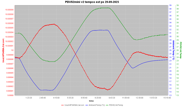
To refresh the memory, this was my tempco measurement of my PDVS 2 mini v2 without tempco correction:
Full size graph:
PDVS2mini-v2-tempco-ext-ps-29-09-2025-1200pix.pngI redid this measurement, but now with the new v2.26 firmware, and with the tempco correction enabled.
For the TC correction factor I used -0.9ppm/°C. This is the tempco I found for
my PDVS2 mini v2 in my previous measurements.
The measurement setup was the same as in previous measurements, and I tried to duplicate the measurement above as good as possible. Following previous comments, I also measured relative humidity in the measurement box. (not shown in the chart)
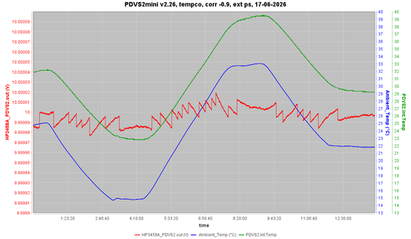
The resulting PDVS 2 Mini v2 tempco measurement
with tempco correction:
 PDVS2mini-v226,_tempco,_corr_-0.9,_ext-ps,_17-06-2026-1200pix.png
The PDVS 2 Mini v2 was freshly calibrated to the 3458A, and set to 10V output.
The red trace is the PDVS 2 Mini output, blue is the ambient temperature (sensor in the same box as the PDVS 2 Mini), and green is the internal temperature of the PDVS 2 Mini.
Comparing the two graphs above, in the non-tempco corrected graph there is a 15ppm output deviation over a 15°C internal temperature change.
With the tempco correction enabled this is reduced to only 4ppm output deviation over the same internal temperature change!
After having done the earlier tempco measurements, I always had an eye on the internal temperature on the PDVS 2 Mini display. And was guestimating the expected offset from the nominal output value.
Now, with the tempco correction enabled, I know it will never be more then 2 ppm from the nominal value. (Which is much better than the specification)
Comparing the two graphs above also shows clearly how the tempco correction is working. Using the original hardware, the new software can only correct in DAC steps. Hence the jumps in the graph.
Personally, I would like those jumps to be as small as possible (one DAC step). This strategy would mean that there should be a correction as soon as the output has drifted more than one DAC step. Maximum error would be 1ppm @ 10V output.
Looking at the graph, this is not always the case. Look for example around 2:45 or 7:30 hours.
Indeed, wrytech has used a somewhat different strategy, aimed at making the TC correction less obvious in normal use.
From the
wrytech blog:
To avoid unnecessary small fluctuations, a 0.2 K deadband is implemented. With TCC enabled, a correction is applied in one of three cases:
- the set voltage is changed
- TCC is enabled
- the internal temperature has changed by more than 0.2 K since the last correction
I have been using a beta firmware version with this TC correction for some time, and I liked it a lot. The added accuracy is a big plus. The correction steps did not bother me. Do not forget that, at 10V output, one DAC step is only one last digit on 6,5 digit DMM.
And, of course, in applications where a constant reference voltage, without possible steps, is more important than it's absolute accuracy, one can always turn the TC correction off in the menu.
Another advantage of the TC correction is the much quicker stabilisation of the PDVS 2 Mini v2 after power-up. Before I waited 1...1,5 hours before the PDVS 2 Mini had stabilised its internal temperature and output. Now with TC correction this is only 15 minutes!
regards, Gertjan.
edit: typos

 Home
Home Help
Help Search
 Login
Login Register


