My own Keithley 6430 fA-SMU repair update. Thanks to TheSteve, xDevs.com also acquired own broken 6430 unit (w/o PA), with diagnosis "no output".

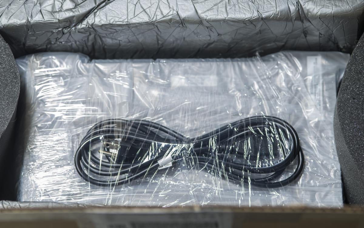
Received very well packed device, leaving no chance to easy damage of fragile instrument:
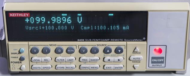
First smell check didn't reveal any issue, so turning on confirmed display operation, responsive buttons and only factory calibration, with count = 1.
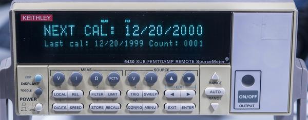
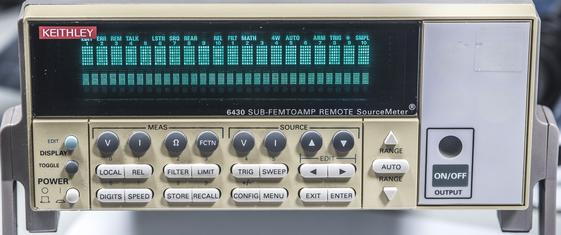
Calibration dates as received and VFD segments brightness are good. Looks like box was never calibrated after factory.

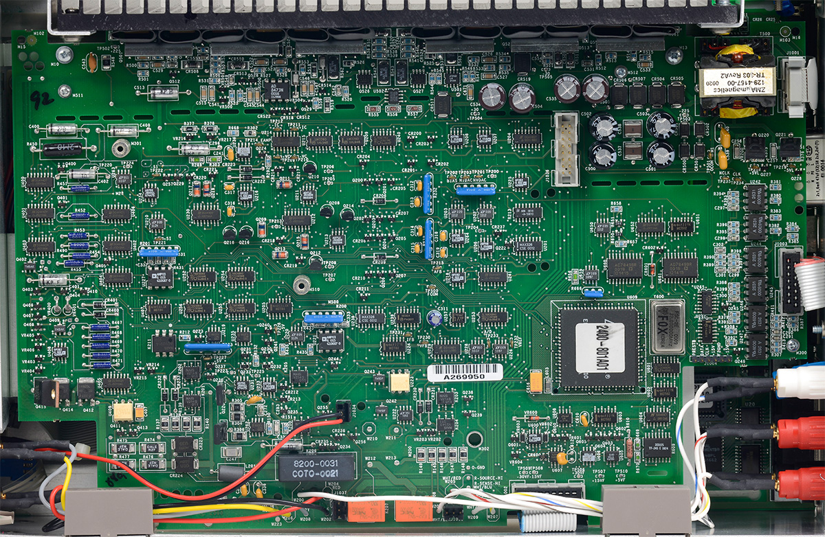
Check with DMM at the output indeed confirmed seller's diagnosis, no output for either current or voltage. Four screws and 5 minutes later:
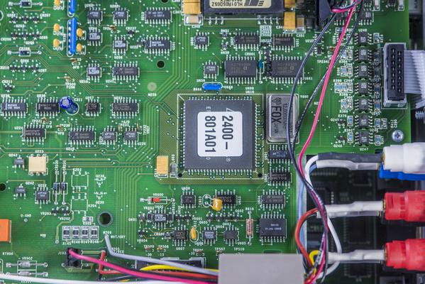
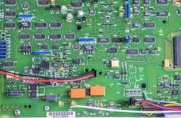
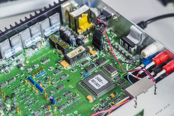
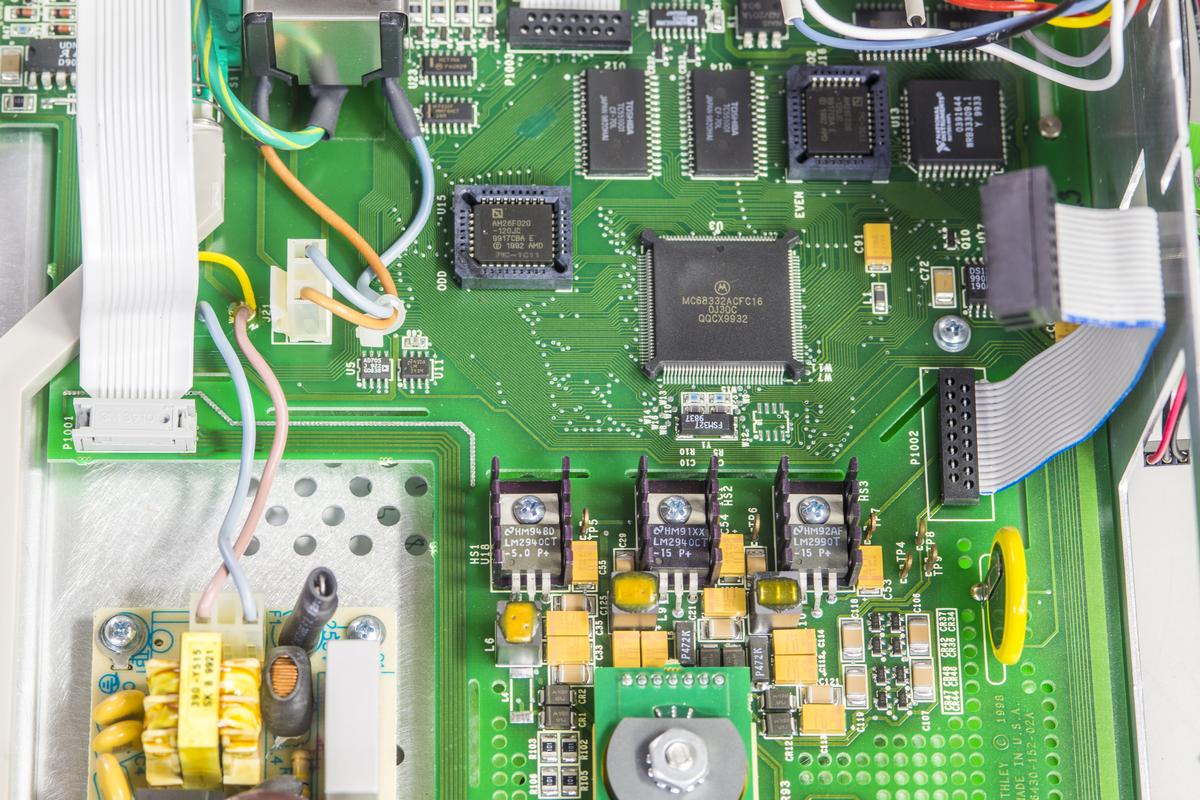
Analog PCB is based from Keithley 2400 SMU, with exception of 1.05A range. Good old Keithley 2400 dual-slope integrating ADC, which is in fact Keithley 2000 ADC + additional digital stuff to control onboard I-DAC and V-DACs and handle source-meter functions like sweeps, guarding, etc. Sadly reference is not LM399, but a compensated zener diode.
Photo of K2400 analog PCB shown on next image to refresh memory.
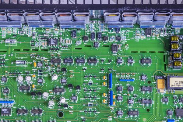
There are additional modifications for external 6430 very low-current amplifier. These include isolated 1W DC-DC "Murata/Power Convertibles HL01R05D05Z":https://xdevs.com/doc/Keithley/6430/pdf/tdc_hl01rzc-55873.pdf and extra optocouplers for SPI interface to 6430 preamplifier. DC-DC specified for 100mV[~pk-pk~] max noise in DC to 10MHz bandwidth and isolation capacitance just 25 pF.
Closed look revealed the problem

:
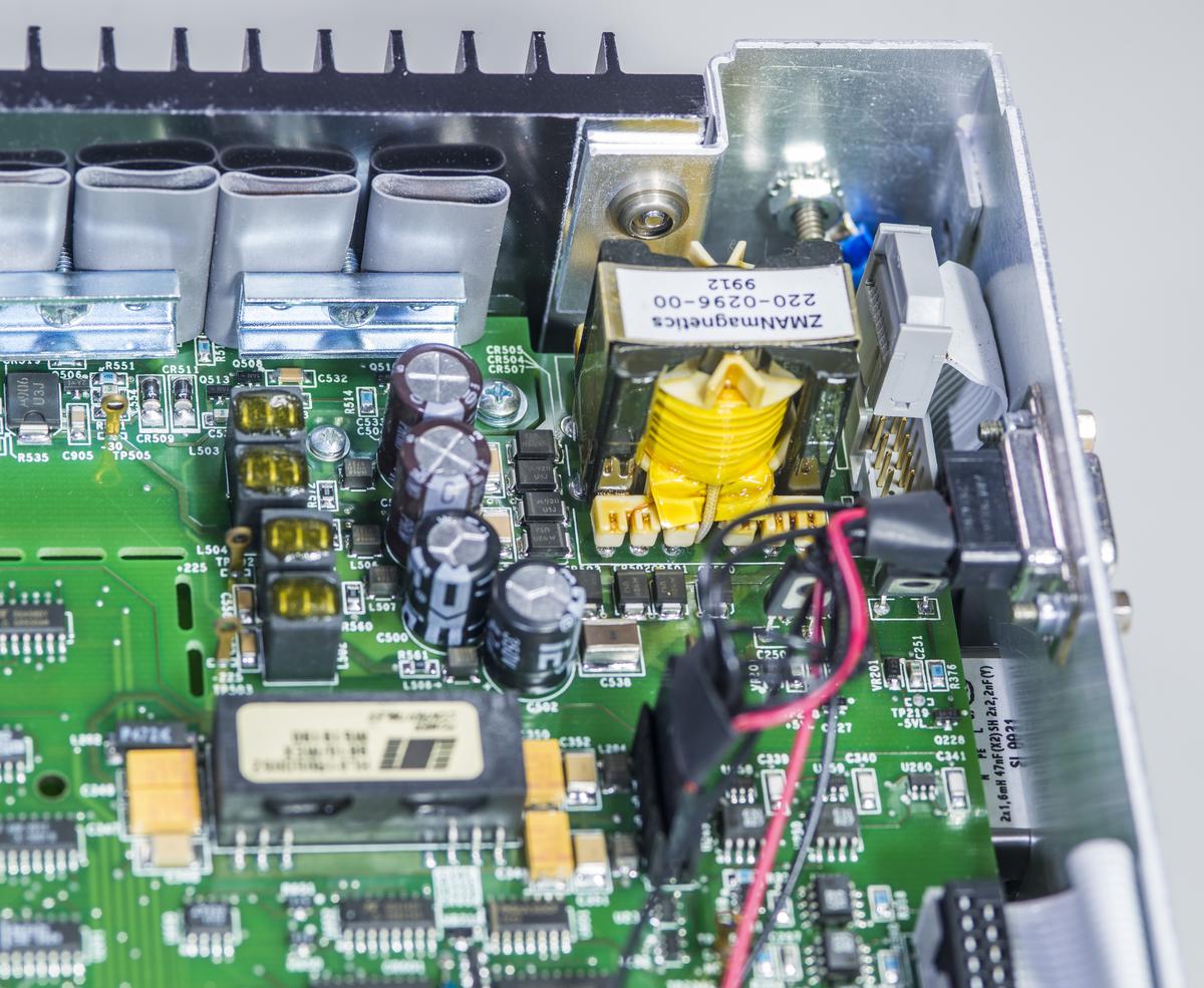
Look closer in top right corner. See anything obvious? It can't be only that, right? It would be too easy.

But yes, after restoring connection to analog board power supply input indeed made unit fully functional again.
So much for repair in The Signal Path style

. I almost feel violated, that we had no chance to dig into SMU analog board troubleshooting
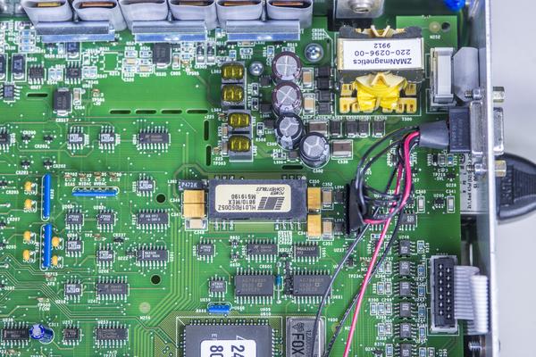
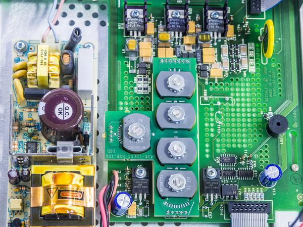
Since we in here anyway, let's remove analog board and see on the digital/power supply boards located under.
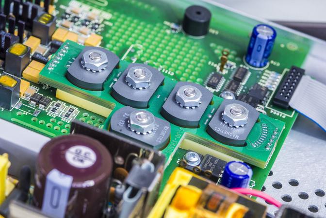
Keithley 6430 using special multicore planar transformer assembly on 16-layer PCB to provide low-noise high-isolation power to analog board. Anybody knows what is all this magic about?
I'd guess this transformer design used to provide low leakage in power supply DC/DC that feeds analog board output stage?
Standard
Keithley 2400 does not have any of this fancy stuff, but overall design is very similar.
Otherwise this is just usual Keithley SMU and it works exactly same way (minus the 1.05A current range) as 2400 when Keithley 6430 amplifier is not connected.
There are no front terminals available with K6430, so output/input provided at the rear ports only.
Quick calibration and checks for 10V and 1V source:
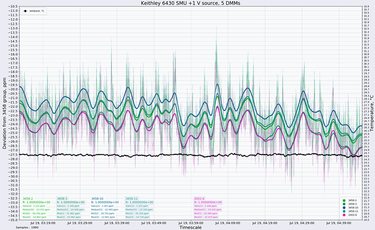
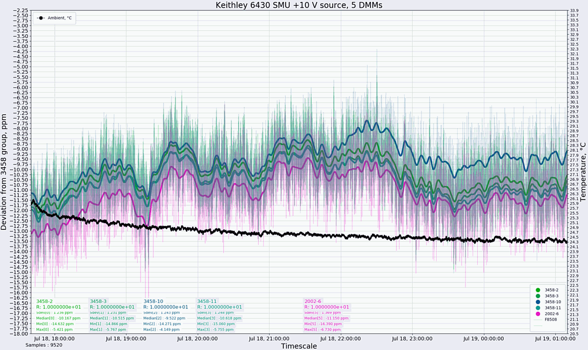
Noise is not great, so perhaps we should pimp this unit with LTZ1000A reference, aye? (Not that K6430 is designed to be low-noise voltage source, it's performance marvels lie in picoampere current domain with preamplifier head).
Calibraiton of the box is "simple", with help of 3458A and set of 100Meg, 1Gohm, 10Gohm and 100Gohm resistors (usually part of Keithley 5156 kit, which I do not have (yet?)).
I didn't tried it with PA yet.


