Author Topic: Ultra Precision Reference LTZ1000  (Read 1344234 times)

0 Members and 4 Guests are viewing this topic.

Offline Alex Nikitin

  • Super Contributor
  • ***
  • Posts: 1177
  • Country: gb
  • Femtoampnut and Tapehead.
    • A.N.T. Audio
Re: Ultra Precision Reference LTZ1000
« Reply #1200 on: December 25, 2015, 12:30:32 am »
Christmas presents  ;) !

Cheers

Alex


Offline Galaxyrise

  • Frequent Contributor
  • **
  • Posts: 531
  • Country: us
Re: Ultra Precision Reference LTZ1000
« Reply #1201 on: December 25, 2015, 04:25:12 am »

I have build my 4x LTZ1000 with focus on minimal long term drift. Based on recommendation from Bob Dobkin R2/R3 is 100k, die temperature to 45°C (12k/1k). For zener current change from 5mA to 7,2 mA I have no opinion.


Hi Andreas, reducing the zener current sensing resistor from 120 to 100 Ohm would increase the current from 5 to 6mA. It is just I have already some 100 ohm Bulk Foil resistors, that is all. Also I use "non-A" version so the additional 7.5mW dissipation should not be a problem. If required I'll just increase the temperature a bit. I may use a metal can LM35 to accurately measure the case temperature of the LTZ1000.

Curious where these current numbers are coming from. I thought the datasheet values result in ~4mA, not 5.  Even taking into account the Vbe rise from reduced temperature, I'd still think 100R is around 5ma.  (This is consistent with measurements I have made of my own LTZ1000, too.)

Remember that the datasheet lists +-10C temperature variation! So 12k:1k isn't reliably 45C (unless you've measured your own unit to be sure, of course.)

Measuring the temperature coefficients of mine is something I did this holiday, and I had a bit of trouble with it.  (I need a proper climate-controlled box...) I got -2.57mV/C for Q1, -2.1mV/C for Q2, 5.5C self heating (4mA zener current, non-A version, not quite in free air) and 55ppm/C for the reference voltage.  Is that consistent with other people's measurements? My gut is that I got the TC of Q1 off by about 10%.  I was using Pin4 as the die thermometer, so if the other numbers seem off by 10% it would be confirmation of my suspicion.
I am but an egg
 

Offline plesa

  • Frequent Contributor
  • **
  • Posts: 965
  • Country: se
Re: Ultra Precision Reference LTZ1000
« Reply #1202 on: December 25, 2015, 09:35:16 am »
Christmas presents  ;) !

Cheers

Alex


Santa has pretty recent LTZ1000:) What resistor you are going to use?

Remember that the datasheet lists +-10C temperature variation! So 12k:1k isn't reliably 45C (unless you've measured your own unit to be sure, of course.)
I measured 4x LTZ1000 and difference between them was 2K, of course you needs to measure Vbe. All are in region 42-44°C with 12k/1k.

I did not measure self heating but I'm curious to measure it, maybe I will buy another LTZ1000 to measure self heating for 4mA to 16mA zener current.
« Last Edit: December 25, 2015, 09:59:55 am by plesa »
 

Offline Alex Nikitin

  • Super Contributor
  • ***
  • Posts: 1177
  • Country: gb
  • Femtoampnut and Tapehead.
    • A.N.T. Audio
Re: Ultra Precision Reference LTZ1000
« Reply #1203 on: December 25, 2015, 10:59:08 am »
Santa has pretty recent LTZ1000:) What resistor you are going to use?

 Digikey Santa was very quick, I've ordered the chip on 22nd and received it on 24th! I've found some 110 Ohm W/W Ultrohm, may use that, or 100 Ohm Bulk Foil.

Cheers

Alex
« Last Edit: December 25, 2015, 11:01:42 am by Alex Nikitin »
 

Offline Andreas

  • Super Contributor
  • ***
  • Posts: 3246
  • Country: de
Re: Ultra Precision Reference LTZ1000
« Reply #1204 on: December 25, 2015, 03:13:17 pm »
I got -2.57mV/C for Q1, -2.1mV/C for Q2, 5.5C self heating
...
so if the other numbers seem off by 10% it would be confirmation of my suspicion.

Hello,

how did you measure that?
Any switchmode power supply involved.
Long measurement lines?

The both bases are very sensitive to noise from environment.
I recommend battery supply + to put a capacitor between base + emitter of the temperature sensing transistor.
(on the current loop there is already the 22nF).

With best regards

Andreas
 

Online chuckb

  • Frequent Contributor
  • **
  • Posts: 342
  • Country: us
Re: Ultra Precision Reference LTZ1000
« Reply #1205 on: December 25, 2015, 04:02:32 pm »
I really enjoy this discussion of the great LTZ1000 Zener. Now it's my turn to contribute a few items.
I had a damaged LTZ1000A from 1995 so I opened it up. I was a little careless with the grinder and damage a few bond wires. Then I took the chip to a friend with a $60,000 microscope. He could rotate things so we could get a relatively clear side view of the chip and it's attachment glue. The chip looks to be 15 mil thick (0.015 inches) and the glue is 5 mil. It's hard to measure the size of the insulating spheres in the glue but they look to be around 2.5-3 mil in diameter.

Thanks for all the great discussions!
 
The following users thanked this post: quarks

Offline TiN

  • Super Contributor
  • ***
  • Posts: 4543
  • Country: ua
    • xDevs.com
Re: Ultra Precision Reference LTZ1000
« Reply #1206 on: December 25, 2015, 04:08:40 pm »
Those are some great photos, thank you. Would be interesting to see similar ones for non-A in future as well.
YouTube | Metrology IRC Chat room | Let's share T&M documentation? Upload! No upload limits for firmwares, photos, files.
 

Offline dr.diesel

  • Super Contributor
  • ***
  • Posts: 2214
  • Country: us
  • Cramming the magic smoke back in...
Re: Ultra Precision Reference LTZ1000
« Reply #1207 on: December 25, 2015, 04:53:53 pm »
I really enjoy this discussion of the great LTZ1000 Zener. Now it's my turn to contribute a few items.

Thanks Chuck! 

Would love to see a LTFLU as well.

Offline Andreas

  • Super Contributor
  • ***
  • Posts: 3246
  • Country: de
Re: Ultra Precision Reference LTZ1000
« Reply #1208 on: December 25, 2015, 06:19:52 pm »
Thanks for all the great discussions!

Hello Chuck,

beautiful pictures: thank you.

With best regards

Andreas
 

Offline Andreas

  • Super Contributor
  • ***
  • Posts: 3246
  • Country: de
Re: Ultra Precision Reference LTZ1000
« Reply #1209 on: December 25, 2015, 11:09:12 pm »
Hello,

"first firing" of PCB #5 with LTC2057 and dummy zener. (connected with spring clips to the resistors).

Battery voltage:      UBat 16.98V
14V after LTC1763: U14  14.011V
current without dummy LTZ: 4.22mA
(expected value around 4.7mA for the 3 LTC2057 = 3*0.9mA + LTC1763 = 0.3mA + some resistors)

After connecting the LTZ simulator:
current with dummy LTZ: 10.96mA??? (expected around 8.9 mA)

Zener voltage    Uz: 6.9656 V
Buffered output UBuf: 6.9650 V
BF245C Gate:    UGate: 5.3052 V (from current regulator OP-Amp)
Voltage R1:        UR1:  0.5805V -> 4.84mA
Voltage R5:        UR5: 0.5464 * 13.5 = 7.38V???
Voltage R6:        UR6: 0.878V (should be the same as R5)
Voltage U2,Pin5:        1.6785V

Mhm: 2 fishy points:
 
1. voltage drop over R6.
This can be explained by a input protection cirquit of the LTC2057.
In datasheet there is a maximum differential input voltage specced from +/-6V
(clamp cirquit over the inputs).
So obviously the Setpoint divider (12K5/1K) gets some current from the 70K pull-up resistor
across the inputs of the LTC2057 because the temperature sensing transistor is missing.
-> this should be no issue when the temperature regulator is working.

2. where comes the excess current from:
Will have to oscilloscope the current regulator loop.

CHA (blue) ON-signal from function generator 2Hz 20% duty.
CHB (red)  current (as voltage over R1 = 120R)
CHC (green) 14V regulated voltage LTC1763

The current over R1 looks nearly perfect.
Relative low overshoot when switching on. (max 650mV = 5.4mA around 12%)
The LTC2057 regulates dammned fast to the final value.
I remember that this was much more with the LT1013 of my previous design.
Flat behaviour in "ON" state.
Only during drop-out near 8V supply when switching off/on some small oscillations.

Strange: from where does the excess current come from?

with best regards

Andreas
 

Offline alanambrose

  • Frequent Contributor
  • **
  • Posts: 377
  • Country: gb
Re: Ultra Precision Reference LTZ1000
« Reply #1210 on: December 26, 2015, 12:06:55 am »
V interesting pics of A version. Does anyone have any ideas what the unused bonding points are used for? Would it be possible to connect to them? Would this be interesting?

A.
“A foolish consistency is the hobgoblin of little minds"
 

Offline plesa

  • Frequent Contributor
  • **
  • Posts: 965
  • Country: se
Re: Ultra Precision Reference LTZ1000
« Reply #1211 on: December 26, 2015, 12:17:08 am »
V interesting pics of A version. Does anyone have any ideas what the unused bonding points are used for? Would it be possible to connect to them? Would this be interesting?

A.

They are for two inner heater elements. It has been discussed here while ago when I posted  images from TiN damaged LTZ1000ACH.
https://doc.xdevs.com/doc/xDevs.com/KX/Die_LTZ1000_small.jpg
« Last Edit: December 26, 2015, 12:19:08 am by plesa »
 

Offline alanambrose

  • Frequent Contributor
  • **
  • Posts: 377
  • Country: gb
Re: Ultra Precision Reference LTZ1000
« Reply #1212 on: December 26, 2015, 12:36:56 am »
Thanks, I see here:

https://www.eevblog.com/forum/projects/ultra-precision-reference-ltz1000/1260/

Still curious whether something interesting could be got from those connections?
“A foolish consistency is the hobgoblin of little minds"
 

Online chuckb

  • Frequent Contributor
  • **
  • Posts: 342
  • Country: us
Re: Ultra Precision Reference LTZ1000
« Reply #1213 on: December 26, 2015, 07:07:43 am »
Thanks, I see here:
https://www.eevblog.com/forum/projects/ultra-precision-reference-ltz1000/1260/
Still curious whether something interesting could be got from those connections?

The chip similarities between the LTZ1000 and the LT1088 have always interested me. Attached is a scan from page 4 of App Note 22 in the 1990 LTC Linear Applications Handbook (this is why I never throw any data books away). The online LTC App Note 22 does not have good resolution for the photos. Both chips have concentric heaters. The LT1088 has 50 ohm and 250 ohm heater rings. It also looks like there are two groups of 4 paralleled transistors in the middle along with a strange circular feature. Has anyone put a (now obsolete) LT1088 chip under a microscope? I will upload higher resolution files (12MB) of this page to TiN's ftp site.

If anyone wants to donate an LT1088 or a LTZ1000 non A chip for microscope analysis, I can see about getting some pictures taken. I just got 10 LTZ1000 chips from Digikey but I don't feel like destroying a working part.


Offline Andreas

  • Super Contributor
  • ***
  • Posts: 3246
  • Country: de
Re: Ultra Precision Reference LTZ1000
« Reply #1214 on: December 26, 2015, 01:35:34 pm »
Hello,

got it:

OP-Amp output of Current regulator is oscillating.
But obviously this cannot be seen on the current shunt resistor (120 R).

CHA (blue) ON-signal from function generator 2Hz 20% duty.
CHB (red)  current (as voltage over R1 = 120R)
CHC (green) 14V regulated voltage LTC1763
CHD (yellow) gate of BF245C/PIN1 of U2

When zooming into the interesting part: 400mV amplitude and 460kHz.
-> the LTC2057 is really fast.

First try: remove the EMI capacitor C15 which I added for the LT1013
into the cirquit to enhance the behavior when a switchmode charger is connected.
-> it works
A manual try of different capacitors between 1 nF and 1uF shows that the cirquit
oscillates with all values. So the LTC2057 is not usable for this kind of EMC-hardening.
-> to avoid problems with the heater cirquit also C14 has to be removed.

After changes:
the cirquit works under all tested conditions.
Only small oscillations or overshoots when running out of or into drop out mode (around 8V supply).

With best regards

Andreas
 

Offline alanambrose

  • Frequent Contributor
  • **
  • Posts: 377
  • Country: gb
Re: Ultra Precision Reference LTZ1000
« Reply #1215 on: December 27, 2015, 02:53:48 pm »
@EmmanuelFaure

Hi, sorry to be slow replying - xmas stuff plus I was reading the article and thinking your post over. Thanks for the calculations and the link.

>>> The power required to maintain the temperature equilibrium, i.e. just to compensate the leaks, is : P=S.Lambda.Delta_T, which is roughly (0.05*0.05)*6*0.04*(50-20) = 0.018W. It's not that bad :)

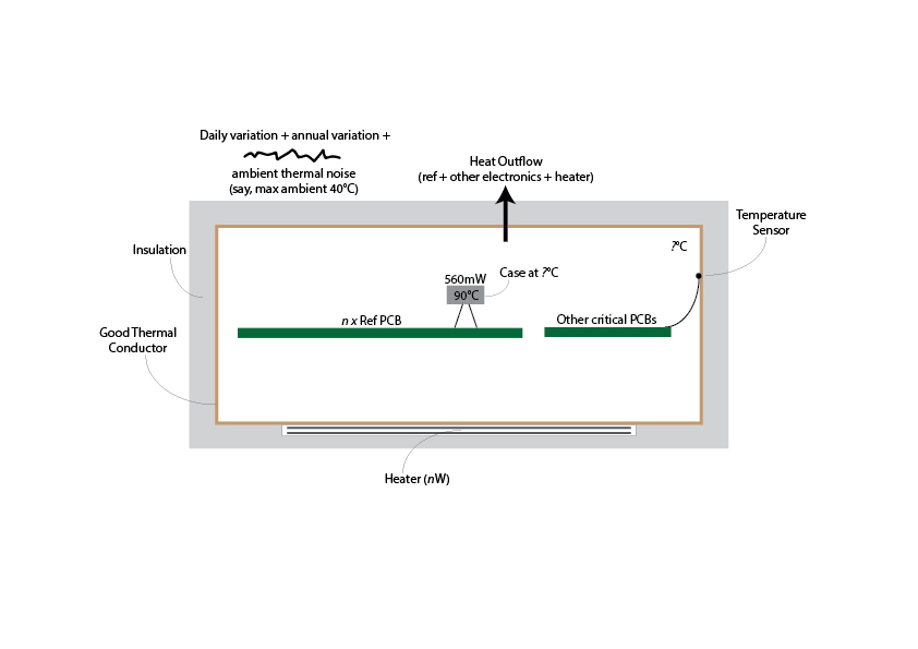
A single LTZ1000A board dissipates ~560mW (26mA heater + 5mA ref @ 18V) at ~22C ambient, so that suggests less insulation is needed. (The LTZ case is ~40C in this case with the die at ~90C).

The article is interesting - pity it doesn't have any pictures. One good thought is that the thermal control needs to be inside the thermally-controlled environment.

>>> With some clever design you can integrate the heating resistor + controller directly on the pcb, and you save a lot of assembly work & trouble.

Good point.

>>> Filtering daily temperature variations would be quite impractical because it would require an enormous mass/volume of thermal mass and insulation. The best way is the active/feedback control method.

Agreed, so the thermal capacity should filter out the ambient thermal noise and the active feedback the daily and annual slow variation.

>>> The key to successful thermal filtering is a good insulation AND a good thermal capacity.

So if some typical lab thermal noise was measured, that should let us calculate the required thermal capacity? This is similar-ish to a simple LP filter?

Is this the picture (below)?

I can't quite see the best way to get at the unknowns right now (target temperature for thermally controlled environment / heater power / etc). Is this a control theory problem or are there some rules-of-thumb?

Regards, Alan


« Last Edit: December 27, 2015, 02:58:01 pm by alanambrose »
“A foolish consistency is the hobgoblin of little minds"
 

Offline Galaxyrise

  • Frequent Contributor
  • **
  • Posts: 531
  • Country: us
Re: Ultra Precision Reference LTZ1000
« Reply #1216 on: December 27, 2015, 06:11:53 pm »
The power required to maintain the temperature equilibrium, i.e. just to compensate the leaks, is : P=S.Lambda.Delta_T, which is roughly (0.05*0.05)*6*0.04*(50-20) = 0.018W. It's not that bad :)
(Also @alanambrose)
That result looks fishy to me.  Dimensional analysis: m*m*(K*m*m/W)*K != W.  I think you mean to divide by 0.04: 11.25W. You can easily get better (and thicker!) insulation, like Foamular would be almost 20x better at its default 1" thickness so you're "only" looking at 700mW.

I am exploring an approach not unlike this, but I'm opting to cool the metal shell instead of heating it.  My goal is that the ref stays with +-10 of room temperature through the power cycle.
« Last Edit: December 27, 2015, 06:31:55 pm by Galaxyrise »
I am but an egg
 

Offline Kleinstein

  • Super Contributor
  • ***
  • Posts: 14197
  • Country: de
Re: Ultra Precision Reference LTZ1000
« Reply #1217 on: December 27, 2015, 07:14:26 pm »
The Power is caclulates as area * delta T * thermal conductivity / thickness of isulation. So with 20 degree temperature difference and 1 cm thickness, I get 1.2 W. That is not little, but also not that bad. Even 2 cm of isolation is not too much.

The power of the circuit inside should be kept small, as to keep the minimum temperature low or the maximum room temperature high. But even if the oven gets out of regulation at more than 30 C in the room this is still an improvent.

The critical part of the LTZ1000 circuit only needs about  6  mA at about 7.x volts plus the heater - this is 40-50 mW. In an controlled enviroment not much power for the heater is needed, maybe a similar amount at most - just to get some room for regulation.  Things like the OPs and especially the current driving transistor(s) should be better outside - also normal LTZ1000 circuits put the transistor that drives the heater and possible power resistors well away from the rest.
 

Offline Galaxyrise

  • Frequent Contributor
  • **
  • Posts: 531
  • Country: us
Re: Ultra Precision Reference LTZ1000
« Reply #1218 on: December 27, 2015, 08:10:51 pm »
The Power is caclulates as area * delta T * thermal conductivity / thickness of isulation. So with 20 degree temperature difference and 1 cm thickness, I get 1.2 W. That is not little, but also not that bad. Even 2 cm of isolation is not too much.
Ah, I'd guessed the 0.04 was an R-Value (so power=area*detlaT/R), but your correction makes more sense: 0.04 is awfully small for a 1cm polystyrene R-Value. I was certain something was up, though :)
I am but an egg
 

Offline Galaxyrise

  • Frequent Contributor
  • **
  • Posts: 531
  • Country: us
Re: Ultra Precision Reference LTZ1000
« Reply #1219 on: December 27, 2015, 08:48:39 pm »
OP-Amp output of Current regulator is oscillating.

First try: remove the EMI capacitor C15 which I added for the LT1013
-> to avoid problems with the heater cirquit also C14 has to be removed.

I also had trouble with oscillations using your circuit on voltnuts.  However, I opted to remove C12.  I didn't check for oscillation on the heater side, but I would think C13 would be better to remove than C14?  However, I'm using a LT1112 right now; I wanted to run without a chopper at first and then introduce the chopper to see how that affected output spectrum. 

(Just to make sure we're reference the same schematic: I have C11 from pin6 to pin7, C12 from pin4 to pin 7, C13 from OUT to IN- of the temp opamp, C14 from IN- to IN+ of the temp opamp, and C15 from IN- to IN+ of the current opamp)
I am but an egg
 

Offline Andreas

  • Super Contributor
  • ***
  • Posts: 3246
  • Country: de
Re: Ultra Precision Reference LTZ1000
« Reply #1220 on: December 27, 2015, 09:15:45 pm »
I also had trouble with oscillations using your circuit on voltnuts.  However, I opted to remove C12.  I didn't check for oscillation on the heater side, but I would think C13 would be better to remove than C14?  However, I'm using a LT1112 right now; I wanted to run without a chopper at first and then introduce the chopper to see how that affected output spectrum. 

(Just to make sure we're reference the same schematic: I have C11 from pin6 to pin7, C12 from pin4 to pin 7, C13 from OUT to IN- of the temp opamp, C14 from IN- to IN+ of the temp opamp, and C15 from IN- to IN+ of the current opamp)

Hello,

the current schematic is here:
https://www.eevblog.com/forum/projects/ultra-precision-reference-ltz1000/?action=dlattach;attach=189655

unfortunately there is no preview of the PDF visible in my post of yesterday:
https://www.eevblog.com/forum/projects/ultra-precision-reference-ltz1000/msg829618/#msg829618
so the LTZ1047B.PDF is somewhat hidden.

C12 is uncritical for oscillations, as long as R19 (which is not in LT cirquit diagram) + C8 are populated.
C12 is at the most sensitive point of the cirquit so it supresses a lot of EMI effects.

The idea of C14, C15 is that a capacitor from OP-Amp GND-Pin to the negative input will always be critical for oscillations.
Between +/- pin normally the voltage is essential zero. So a capacitor is less critical for oscillations here.
(and with the capacitor from + pin to GND a series connection to GND is given against EMI.)
This works for the LT1013 in my cirquit. But it seems that faster OPs like the LTC2057 do not like this.

By the way: with a LT1112 you will need a negative supply rail for the OPs.
The common mode range is not sufficient for a single supply operation.

with best regards

Andreas
« Last Edit: December 27, 2015, 09:39:28 pm by Andreas »
 
The following users thanked this post: cellularmitosis

Offline Galaxyrise

  • Frequent Contributor
  • **
  • Posts: 531
  • Country: us
Re: Ultra Precision Reference LTZ1000
« Reply #1221 on: December 27, 2015, 11:17:02 pm »
C12 is uncritical for oscillations, as long as R19 (which is not in LT cirquit diagram) + C8 are populated.
C12 is at the most sensitive point of the cirquit so it supresses a lot of EMI effects.
Thanks for the pdf re-link, I had indeed missed it in the images. And I didn't have R19 + C8, so C12 was a problem.

Quote
As for C14,
The idea of C14, C15 is that a capacitor from OP-Amp GND-Pin to the negative input will always be critical for oscillations.
Between +/- pin normally the voltage is essential zero. So a capacitor is less critical for oscillations here.
(and with the capacitor from + pin to GND a series connection to GND is given against EMI.)
This works for the LT1013 in my cirquit. But it seems that faster OPs like the LTC2057 do not like this.
Hmm, my experience was that the temperature loop was the most sensitive to EMI, because it could reset the integrator and cause a temperature swing that took minutes to recover.  Something like C14 was how I addressed that issue.  I guess since you've put an integrator on the current loop as well, it could suffer from the same problem. I will have to play with this some more.

Quote
By the way: with a LT1112 you will need a negative supply rail for the OPs.
Yeah, I have pin7 raised by a diode drop relative to the LT1112 V-.  I wanted this anyway so I could buffer pin7.
« Last Edit: December 28, 2015, 04:11:59 am by Galaxyrise »
I am but an egg
 

Offline Andreas

  • Super Contributor
  • ***
  • Posts: 3246
  • Country: de
Re: Ultra Precision Reference LTZ1000
« Reply #1222 on: December 28, 2015, 06:01:53 am »
Hmm, my experience was that the temperature loop was the most sensitive to EMI, because it could reset the integrator and cause a temperature swing that took minutes to recover.  Something like C14 was how I addressed that issue.  I guess since you've put an integrator on the current loop as well, it could suffer from the same problem. I will have to play with this some more.

Of course you are right. The base of the temperature sensing controller is even more sensitive.

But that was a thing that I fixed first, because I saw noise on  the heater voltage in the range of several mV without the capacitor on the Base pin of the temperature loop.
Actually the noise measured was around 6mV pp with sporadic dips of -40mV on a heater voltage of around 5.4V.
I could not imagine that this behaviour is good for a low noise reference.
So I adapted the capacitor from the datron reference cirquit.
With the capacitor the heater noise is reduced to around 0.6 mV pp. Without any dips.

On the current loop the integrator is needed for stability with capacitive loads like C9 (for EMI reason) of the (unbuffered) reference.

with best regards

Andreas


Offline Andreas

  • Super Contributor
  • ***
  • Posts: 3246
  • Country: de
Re: Ultra Precision Reference LTZ1000
« Reply #1223 on: December 28, 2015, 07:56:12 am »
Hello,

first measurements on the 2nd sample LTZ#3 (with LT1013A instead of LTC2057)
with dummy zener. (no heater dummy cirquit).

Current without Zener 3.13 mA.        (around 3.6 mA expected)
Current with dummy zener 7.45 mA. (around 7.8 mA expected)

again the same channels.

CHA (blue) ON-signal from function generator 2Hz 20% duty.
CHB (red)  current (as voltage over R1 = 120R)
CHC (green) 14V regulated voltage LTC1763
CHD (yellow) gate of BF245C/PIN1 of U2

Even with C14+C15 mounted no oscillations on the gate of the FET.
But this time overshoot to around 800mV = 6.7 mA of zener current.
Also the zener voltage shows some overshoot  (CHC (green)  = zener voltage)
of around 240 mV up to 7.2V.
No oscillations on outputs (unbuffered + buffered zener) with decade
capacitors in the range of 1nF - 10uF as load.

Temperature setpoint voltage on R5 = 0.5158V * 13.5 = 6.9633V (the voltage of the dummy zener)
So with LT1013A there is no "cross current" from +/- inputs in case of open regulator loop.

So I will let the C14+C15 mounted for the LT1013A.

with best regards

Andreas


« Last Edit: December 28, 2015, 08:44:40 am by Andreas »
 

Offline Andreas

  • Super Contributor
  • ***
  • Posts: 3246
  • Country: de
Re: Ultra Precision Reference LTZ1000
« Reply #1224 on: December 29, 2015, 10:07:58 pm »
Hello,

and now the money shot:
around $80 per square inch component cost within the "inner circle".

LTZ1000A is now on board.
So ready for further tests.

With best regards

Andreas


Share me

Digg  Facebook  SlashDot  Delicious  Technorati  Twitter  Google  Yahoo
Smf