Author Topic: Ultra Precision Reference LTZ1000  (Read 1339799 times)

0 Members and 3 Guests are viewing this topic.

Offline TiN

  • Super Contributor
  • ***
  • Posts: 4543
  • Country: ua
    • xDevs.com
Re: Ultra Precision Reference LTZ1000
« Reply #1425 on: May 26, 2016, 04:37:38 am »
Have the reference with constant temperature and vary room temp with all gear, taking samples.
Best go both ramps, up and down in temperature. Then you can get linear TC of setup, and approximate result using it as multiplier to actual measurement.
If TC is linear, you can get pretty close.
YouTube | Metrology IRC Chat room | Let's share T&M documentation? Upload! No upload limits for firmwares, photos, files.
 

Offline BU508A

  • Super Contributor
  • ***
  • Posts: 4522
  • Country: de
  • Per aspera ad astra
Re: Ultra Precision Reference LTZ1000
« Reply #1426 on: May 26, 2016, 05:12:49 am »
Hello TiN,

nice article on xdevs.  :clap: :-+

https://xdevs.com/article/kx-ref/
“Chaos is found in greatest abundance wherever order is being sought. It always defeats order, because it is better organized.”            - Terry Pratchett -
 

Online Alex Nikitin

  • Super Contributor
  • ***
  • Posts: 1162
  • Country: gb
  • Femtoampnut and Tapehead.
    • A.N.T. Audio
Re: Ultra Precision Reference LTZ1000
« Reply #1427 on: May 26, 2016, 10:05:43 am »
Hello TiN,

nice article on xdevs.  :clap: :-+

https://xdevs.com/article/kx-ref/

Nice article! Could somebody tell me what is the purpose of CR1 diode in the LTZ1000 circuit there (the one between the heater and ground)?

Cheers

Alex
 

Offline d-smes

  • Regular Contributor
  • *
  • Posts: 101
  • Country: us
Re: Ultra Precision Reference LTZ1000
« Reply #1428 on: May 26, 2016, 10:20:21 am »
Could somebody tell me what is the purpose of CR1 diode in the LTZ1000 circuit there (the one between the heater and ground)?
Read data sheet "Pin Functions" section and reference "Block Diagram".  CR1 diode prevents parasitic substrate diodes within LTZ1000 structure from becoming forward biased.
 

Online Alex Nikitin

  • Super Contributor
  • ***
  • Posts: 1162
  • Country: gb
  • Femtoampnut and Tapehead.
    • A.N.T. Audio
Re: Ultra Precision Reference LTZ1000
« Reply #1429 on: May 26, 2016, 10:28:53 am »
Could somebody tell me what is the purpose of CR1 diode in the LTZ1000 circuit there (the one between the heater and ground)?
Read data sheet "Pin Functions" section and reference "Block Diagram".  CR1 diode prevents parasitic substrate diodes within LTZ1000 structure from becoming forward biased.

1) No, it does not. It can not protect against a negative polarity voltage on the heater (pins 1 and 2) relative to pin 4. Only if that diode is in series with pin 1 than it would be useful.

2) In a circuit with a single supply as in this article, this protection is irrelevant in any case.

Cheers

Alex

« Last Edit: May 26, 2016, 12:47:14 pm by Alex Nikitin »
 

Offline d-smes

  • Regular Contributor
  • *
  • Posts: 101
  • Country: us
Re: Ultra Precision Reference LTZ1000
« Reply #1430 on: May 26, 2016, 07:38:35 pm »
Could somebody tell me what is the purpose of CR1 diode in the LTZ1000 circuit there (the one between the heater and ground)?
Read data sheet "Pin Functions" section and reference "Block Diagram".  CR1 diode prevents parasitic substrate diodes within LTZ1000 structure from becoming forward biased.

1) No, it does not. It can not protect against a negative polarity voltage on the heater (pins 1 and 2) relative to pin 4. Only if that diode is in series with pin 1 than it would be useful.

2) In a circuit with a single supply as in this article, this protection is irrelevant in any case.

Cheers

Alex
I answered assuming the referenced circuit "Schematics 2: xDevs.com KX voltage reference (Rev.B00) reference" was operating in steady-state conditions.  Therefore, it is assumed heater current is flowing which will forward bias CR1 into conduction.  In doing so, pin 2 is now at roughly the same voltage as pin 4 (referenced to pin 7, ground).  In reality, it's slightly positive since the Vf of CR1 (at room temperature) is greater than the Vbe of Q1 (pin 4 to pin 7) which is heated above room temperature (owing to the roughly -2mV/C temperature coefficient of Vbe).  Thus, the substrate diode between pin 2 (cathode) and pin 4 (anode) is reverse biased.  This satisfies the requirement that the substrate diode(s) not be forward biased.
 

Offline Andreas

  • Super Contributor
  • ***
  • Posts: 3238
  • Country: de
Re: Ultra Precision Reference LTZ1000
« Reply #1431 on: May 29, 2016, 04:25:47 pm »
Hello,

Shi(f)t happens ...

I accidently shorted the unbuffered output of my best aged LTZ (LTZ#1) which had a annual drift of about -1 ppm.
This resulted in a low setpoint voltage for the heater -> infinite temperature -> stress + hysteresis to the zener.
After curing a part of the hysteresis by power cycling several times
the remaining shift is about -1.9 ppm.   :-//   |O

By the way: I read in a german forum that precision OP-Amps are not always a perfect means to prevent shorting the output.
The reason is that most of the precision amplifiers have protection diodes between both inputs.
So if a unity gain follower without any series resistors is shorted to GND on the output, the positive input is clamped to 0.7 V.
see figure 3 of OP27 datasheet:
http://www.analog.com/media/en/technical-documentation/data-sheets/OP27.pdf

On my new references I tested short cirquits on the buffered output having around 1 mV influence on the zener voltage.

With best regards

Andreas
 

Offline TiN

  • Super Contributor
  • ***
  • Posts: 4543
  • Country: ua
    • xDevs.com
Re: Ultra Precision Reference LTZ1000
« Reply #1432 on: May 29, 2016, 04:46:57 pm »
Ouch. How long was it shorted? I'm pretty sure that was how my first LTZ chip died, after short temp loop went out of bounds and shorted the zener.
YouTube | Metrology IRC Chat room | Let's share T&M documentation? Upload! No upload limits for firmwares, photos, files.
 

Offline Andreas

  • Super Contributor
  • ***
  • Posts: 3238
  • Country: de
Re: Ultra Precision Reference LTZ1000
« Reply #1433 on: May 29, 2016, 05:34:45 pm »
Hello,

Not really long.

It was a unpowered ADC (LTC2400 with LTC1043) connected to LTZ#1
I had a DMM as difference voltage to LTZ#2.
And I soon recognized during connection that the DMM had not a few mV as expected
but 7V as measurement value.

So perhaps 5 seconds short cirquit time.

With best regards

Andreas
 

Offline zlymex

  • Frequent Contributor
  • **
  • Posts: 556
  • Country: cn
Re: Ultra Precision Reference LTZ1000
« Reply #1434 on: May 30, 2016, 12:38:43 am »
Hello Andreas,

I cannot find the idea 'switched capacitor idea for the 7V->10V boost' of yours mentioned by DiligentMinds.com at the other thread, can you give me the reference?

I had this ideal as well by using a LTC1043 or ADG1236 to multiply 7V by 1.5 times to 10.5V, and use resistor networks to divided down to 10V, I wonder if they are similar. I bought some LTC1043 and ADG1236 long time ago but cannot find time for the implementation. I made some simulation and functionally it's working. I had two LTZ1000 with voltages slightly below 7V that particularly suitable for this kind of application. Also, there are some low voltage compensated zeners(namely 2DW232, 6.3V) which good for this as well.
 

Offline Andreas

  • Super Contributor
  • ***
  • Posts: 3238
  • Country: de
Re: Ultra Precision Reference LTZ1000
« Reply #1435 on: May 30, 2016, 04:57:54 am »
Hello,

one suggestion is here (5.2V out of 7V by *3/4 transfer)

https://www.eevblog.com/forum/projects/building-a-7-decade-voltage-calibrator/msg304819/#msg304819

the other here (* 3/2 transfer to get 10 V out of 7V)

https://www.eevblog.com/forum/projects/building-a-7-decade-voltage-calibrator/msg298350/#msg298350

both cirquits only simulated by now (just had no time to build a complete calibrator).

Edit: and of course you will need a high impedant/low leakage buffer at the output.

with best regards

Andreas
« Last Edit: May 30, 2016, 05:41:08 am by Andreas »
 

Offline zlymex

  • Frequent Contributor
  • **
  • Posts: 556
  • Country: cn
Re: Ultra Precision Reference LTZ1000
« Reply #1436 on: May 30, 2016, 06:50:24 am »
Thanks Andreas, here is my simulation.
« Last Edit: May 30, 2016, 07:10:25 am by zlymex »
 

Offline Andreas

  • Super Contributor
  • ***
  • Posts: 3238
  • Country: de
Re: Ultra Precision Reference LTZ1000
« Reply #1437 on: May 30, 2016, 07:30:14 pm »
Hello,

the cirquit looks good.
But in the diagram the voltage ripple is rather large. (and average voltage too low).
Is the measurement instrument simulated as a pull down resistor ? (which value ?)

So round about estimation is 200ms time constant (50mV ripple in 1 ms).
Which would give a 1 Meg resistor as load.

With best regards

Andreas
 

Offline zlymex

  • Frequent Contributor
  • **
  • Posts: 556
  • Country: cn
Re: Ultra Precision Reference LTZ1000
« Reply #1438 on: May 31, 2016, 01:29:45 am »
That's right, I suspect the simulation program(Multisim) is not very good, and it had difficulty running the simulation(errors, adjustment, roll-back).
There are many times that Multisim gives contradictory results. For instance, how can a Vpp be 221uV but Vrms is 21.1V?
There is no apparent source of leakage from the circuit, there must be some equivalent leakage resistors in the capacitor or in the switch.
 

Offline necessaryevil

  • Regular Contributor
  • *
  • Posts: 133
  • Country: nl
Re: Ultra Precision Reference LTZ1000
« Reply #1439 on: June 02, 2016, 01:35:08 pm »
Hmm... how about a Weston Cell from ebay instead of an LTZ1000? I know, a Josephson voltage standard would be more accurate, but  I don't think they fit on my bench nicely. Also, they are not available on ebay for a price which agrees with my budget.

Quote
. For instance, how can a Vpp be 221uV but Vrms is 21.1V?
DC offset?
 

Offline zlymex

  • Frequent Contributor
  • **
  • Posts: 556
  • Country: cn
Re: Ultra Precision Reference LTZ1000
« Reply #1440 on: June 02, 2016, 02:26:03 pm »
Hmm... how about a Weston Cell from ebay instead of an LTZ1000? I know, a Josephson voltage standard would be more accurate, but  I don't think they fit on my bench nicely. Also, they are not available on ebay for a price which agrees with my budget.

Quote
. For instance, how can a Vpp be 221uV but Vrms is 21.1V?
DC offset?
Poor ones, not worth considering. Good ones, often suffered from transport effect.

There is no DC offset apart from 10V, which is much smaller than 21.1V. I do come across several instances where the output of an opamp gone up to 10kV :palm:
 

Offline Kleinstein

  • Super Contributor
  • ***
  • Posts: 14159
  • Country: de
Re: Ultra Precision Reference LTZ1000
« Reply #1441 on: June 02, 2016, 03:05:55 pm »
Sometimes simulations have trouble with convergence and start with crazy values like 10 kV at an OP.  This can also happen with LTspice, not a Multisim exclusive. The 21 V RMS at 220 µV_pp look faulty - but at least the is obvious.

The ripple could be real, because if internal effects in the CMOS switches. So switches have significant charge injection. Though I don't think the effect should be that large - could be a problem with the model. Another point could be not so perfect capacitors used in the simulation. As perfect parts sometimes cause trouble in simulations, the program might use more realistic models by default.
 

Offline zlymex

  • Frequent Contributor
  • **
  • Posts: 556
  • Country: cn
Re: Ultra Precision Reference LTZ1000
« Reply #1442 on: June 02, 2016, 04:39:32 pm »
Yes, large capacitor should be chosen to weaken the charge injection effect. They use 1uF most of the time in the datasheet examples. I use smaller values(and 100kHz frequency) in the simulation to speed up the process.
 

Offline necessaryevil

  • Regular Contributor
  • *
  • Posts: 133
  • Country: nl
Re: Ultra Precision Reference LTZ1000
« Reply #1443 on: June 02, 2016, 05:02:21 pm »
I'm sure circuit simulators are great tools, but they are no panacea. Creating a good simulation model is probably more difficult than breadbording (and perhaps than flying to the moon).
 

Offline Kleinstein

  • Super Contributor
  • ***
  • Posts: 14159
  • Country: de
Re: Ultra Precision Reference LTZ1000
« Reply #1444 on: July 20, 2016, 09:14:19 pm »
The LT1677 is not such a good choice, the LT1013 is better in at least three parameters:
The current noise of the LT1677 is rather high (1.2 pA/Sqrt(Hz) at 10 Hz - compared to 0.07 pA/Sqrt(Hz) for the LT1013.
As the OPs sense the rather high output signals at the collectors (e.g. 70 K impedance), current noise in the pA range is more important than low voltage noise.  So the LT1677 is lower noise only with low source impedance (< about 30 K), but not with the typical LTZ1000 circuit.

At low input voltage, the bias current is huge (e.g. 400 nA) and thus a negative supply is needed. Otherwise the LT1677 would be worse than an LM358.

The other point is current consumption - the LT1677 take quite some extra power (e.g. 6 times more).

Bias current drift could also be worse with the LT1677, though the data-sheet does not specify it.
 

Offline Andreas

  • Super Contributor
  • ***
  • Posts: 3238
  • Country: de
Re: Ultra Precision Reference LTZ1000
« Reply #1445 on: July 20, 2016, 09:21:27 pm »
then the LT1677 is superior to the LT1013 in almost every important spec,

Hello Ken,

really?

I personally believe that for the current regulation loop the amplification should be as high as possible.

At 5 mA (roughly 2K-Ohms) load the LT1013 has a factor 10 higher amplification,
with a power consumption of 1/10 th of the LT1677.

With best regards

Andreas


Offline Kleinstein

  • Super Contributor
  • ***
  • Posts: 14159
  • Country: de
Re: Ultra Precision Reference LTZ1000
« Reply #1446 on: July 20, 2016, 10:52:10 pm »
The dynamic impedance at the transistors collector is not given by voltage divided by current. The transistor is working essentially as a constant current source and thus has a very high output impedance. The typical data-sheets don't give it for such a small U_CE. A simple simulation for the 2N3904 in LTspice is about 500 K. So this node is really about 70 K impedance.

The noise of the LTC1677 (or that of most OPs) would be still swamped be the LTZ1000. But at more than about 30 K source impedance the noise of the LTC1677 is higher than that of the LT1013.

The current regulation loop has the additional gain of the transistor and it's working at an essentially fixed condition. So a limited gain by itself would not be a problem at all. Only when changing with time or temperature it might be a small problem. But with the additional factor of about 200-250 from the transistor, anything above 50.000 should be enough to cause an contribution of less than 1 µV to the output.
 

Offline Kleinstein

  • Super Contributor
  • ***
  • Posts: 14159
  • Country: de
Re: Ultra Precision Reference LTZ1000
« Reply #1447 on: July 21, 2016, 04:59:32 pm »
The impedance at the transistors collector depends on wether you look at the closed loop case, or the open loop case. In close loop the point is rather low impedance (simulation shows something like 300 Ohms, using a 2N3904 model for the transistor). A signal due to added current appears nearly same size at the output. Voltage noise and drift an noise of the OP at low frequencies (e.g. less than about 1 KHz) are attenuated by a factor of about 200. So to compare current and voltage noise one has to reduce the voltage noise by this factor or multiply the current noise or impedance with it. So the effective impedance for the current noise is about 60 kOhms. Not by accident this is the same as the impedance of the node when looking at it in the open circuit noise. So for the choice of the OP one should consider an source impedance of about 60 K (slightly less than the 70 K resistor, due to the finite output admittance of the transistor).

For this high impedance the LT1013 and LTC2057 are good choices, but the LTC1677 or an similar LT1007 are not. So low and stable bias and low current noise are important.

Looking at the simulation of the current loop, there is a rather low phase margin in the 1-10 kHz range. This could become a problem with an AZ OP, as AZ OPs tend to have extra phase shifts in this frequency range. To be on the safe side one might want to modify the circuit to add extra phase margin if an AZ OP is used.
 

Offline TiN

  • Super Contributor
  • ***
  • Posts: 4543
  • Country: ua
    • xDevs.com
Re: Ultra Precision Reference LTZ1000
« Reply #1448 on: August 07, 2016, 07:12:57 pm »
I know some guys here going to hate me for this, but let's do some myth-busting. There are lot of talk about long/short legs, sockets and all that around LTZ-designs.
So here it comes. Built one more module with leftover parts.


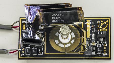
Design configuration:
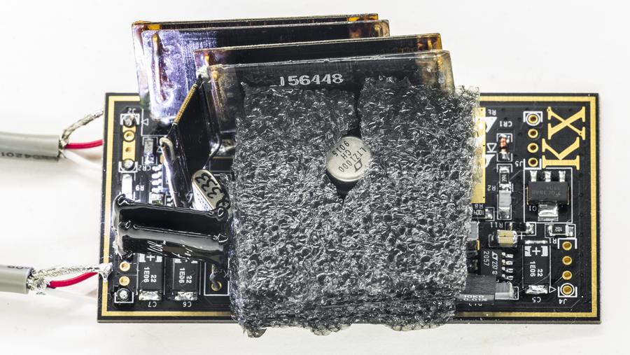
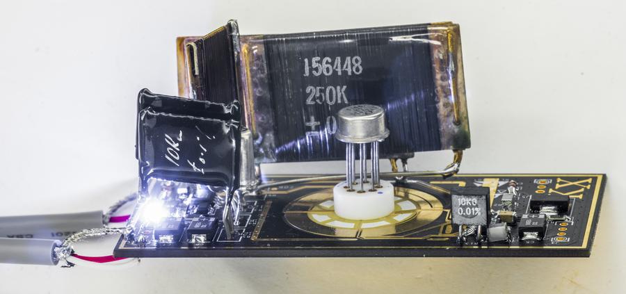
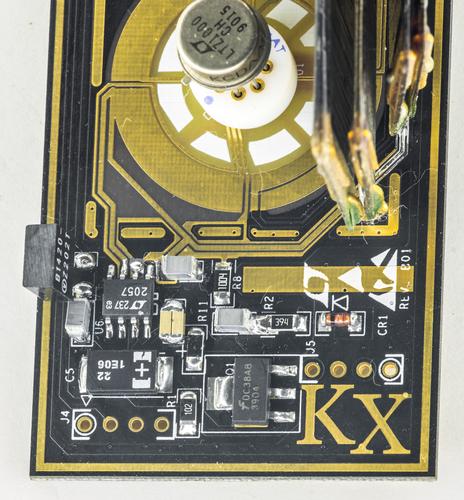
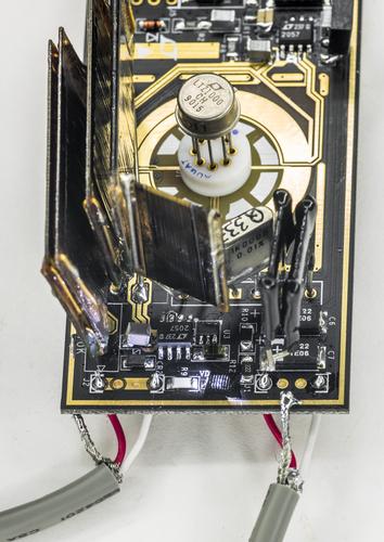
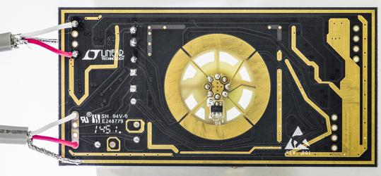
* xDevs.com KX LTZ1000 PCB, Rev.B01 board
* LTZ1000CH made in 1991, legs are NOT trimmed
* AUGAT gold-plated socket for LTZ
* Linear LTC2057 opamps for both drive and thermostat
* VPG VHP 1K000 0.2ppm/K + 10K+2K wirewound for temp setpoint
* Wirewound 120R. 10K is Z202 VPG
* Paralleled Fluke 3ppm/K 100K+250K resistors as 71.5K for bias
* Film capacitors for all signal path locations except 22nF (Which is C0G 1210)
* 392K for LTZ1000CH option installed


Board is covered in box and shielded from airflow now.

Closeup on parts:


Had to bodge some copper wiring to fit these giant resistors..


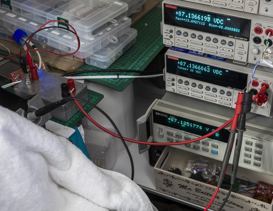
Board is powered from K2400 at +15V and measured via 3458A@NPLC100. Also turned on pair of my previous LTZ modules, hooked to K2002's for comparison.


Live data:


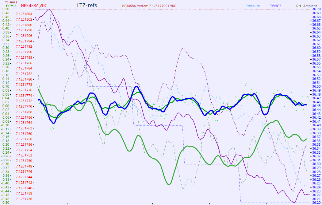
I have 3 more LTZ1000CH from same batch, and dodgy (1ppm shot noise) desoldered LTZ1000ACH from ebay 3458A's PCBA. So I'll have each chip run for some time and then proceed with swapping. Then rotate in opposite direction, to see if any voltage shifts due to socket connections.

If have any ideas - feel free to ask.
YouTube | Metrology IRC Chat room | Let's share T&M documentation? Upload! No upload limits for firmwares, photos, files.
 
The following users thanked this post: dr.diesel, 3g57

Offline Andreas

  • Super Contributor
  • ***
  • Posts: 3238
  • Country: de
Re: Ultra Precision Reference LTZ1000
« Reply #1449 on: August 07, 2016, 09:24:19 pm »
I know some guys here going to hate me for this, but let's do some myth-busting. There are lot of talk about long/short legs, sockets and all that around LTZ-designs.

Hello Illya,

we all can only learn from any experiment.
For me the procedure is clear (at least for the LTZ1000A with 12K5 setpoint resistor).

Step 1:
let the legs long and do not populate R9.
Measure T.C. of reference (with LTZ properly thermal shielded).

Step2:
Shorten legs if T.C. is < 0 T.C. will increase around +40ppb/K for half shortened and around +130ppb/K for full shortened legs.
I think its better to have at least 10 mils distance between PCB and the bottom of the LTZ to avoid stress to the chip.
Measure T.C. of reference again (with LTZ properly thermal shielded).

Step 3:
If T.C. is still <0 populate R9. 400K will compensate around 80 ppb/K. 2 Meg around 20ppb/K.
But this compensation is non-linear.
Measure T.C. of reference again (with LTZ properly thermal shielded) and eventually repeat Step 3.

For the layout:
keep all non constant heat sources away from the LTZ.
The heater transistor is not necessarily a problem if the supply voltage is constant.
But the voltage regulator from changeing battery voltage is critical. (here the slots will help).

With best regards

Andreas


Share me

Digg  Facebook  SlashDot  Delicious  Technorati  Twitter  Google  Yahoo
Smf