Author Topic: Amplify 500mV 0-pk square wave to >2V for PIC MCU  (Read 6095 times)

0 Members and 1 Guest are viewing this topic.

Online PCB.Wiz

  • Super Contributor
  • ***
  • Posts: 1548
  • Country: au
Re: Amplify 500mV 0-pk square wave to >2V for PIC MCU
« Reply #50 on: March 31, 2023, 03:02:23 am »
Thank you.  However, that correction only makes the output a constant +5V, with or without a PIC MCU load, as shown below.
The load connects to the Q1 collector
Most Spice pgms treat 1.5M as milli, try 1.5Meg
 

Offline JDWTopic starter

  • Frequent Contributor
  • **
  • Posts: 336
  • Country: jp
Re: Amplify 500mV 0-pk square wave to >2V for PIC MCU
« Reply #51 on: March 31, 2023, 04:45:54 am »
Thank you.  However, that correction only makes the output a constant +5V, with or without a PIC MCU load, as shown below.
The load connects to the Q1 collector
Most Spice pgms treat 1.5M as milli, try 1.5Meg

In the original post presenting the circuit to me, Q2 is the label on the NPN at left, and Q1 is the label on the NPN at right. So in my circuit, my 1.5M (which absolutely is Mega-ohm in my sim) load is already connected to the collector of that NPN labeled Q1 (at right).

Or do you mean to tell me to connect my 1.5MΩ load resistor to the collector of Q2, which again, is the NPN at left?  (It's collector now connects to R1.)  Even if I do that, the output across the 1.5MΩ load resistor is a rock solid 5.0v that never budges.
 

Offline Kim Christensen

  • Super Contributor
  • ***
  • Posts: 1327
  • Country: ca
Re: Amplify 500mV 0-pk square wave to >2V for PIC MCU
« Reply #52 on: March 31, 2023, 05:00:15 am »
You need to do this:
 
The following users thanked this post: JDW

Offline JDWTopic starter

  • Frequent Contributor
  • **
  • Posts: 336
  • Country: jp
Re: Amplify 500mV 0-pk square wave to >2V for PIC MCU
« Reply #53 on: March 31, 2023, 05:25:03 am »
You need to do this:

Oh my.  Well, thank you.  I'm one of those massively overtaxed multitaskers who misses the little detail now and then.  It simulates!  See attachments.  Output swings between 61.274mV and 4.68V with a 1.5MΩ load resistor.  I will now breadboard this and if it passes the bench test, I will then proceed with an in-vehicle test.

I still have my voltage comparator parts in the mail, and that may prove the most reliable solution in the end.  But parts count and cost do matter, so we shall see.  Because this is for vehicle use, I would need to break up that 3.3kΩ single resistor into two pieces with a BAT54 in the middle (with one diode tied to GND and the other to surge protected protected +12V) to ensure a voltage spike won't kill Q2.

Anyway, thank you for the hand-holding and detailed clarification, Kim!

BREADBOARD TEST FAILED:  The output at the collector of Q1 when using my Function Generator is basically zero.  Well, a 50mV 0-pk voltage level, but that's it.  No pulsing at all.
« Last Edit: March 31, 2023, 08:24:13 am by JDW »
 

Offline peter-h

  • Super Contributor
  • ***
  • Posts: 3700
  • Country: gb
  • Doing electronics since the 1960s...
Re: Amplify 500mV 0-pk square wave to >2V for PIC MCU
« Reply #54 on: March 31, 2023, 07:11:49 am »
Ntnico is half right :) my circuit needs a resistor in the emitter of the transistor to eliminate the loading on the up-swing.

If you want a solution which works down to DC then you basically need to build a comparator with a +250mV threshold, and it would need a PNP transistor.

Or use a TL331 :)

« Last Edit: March 31, 2023, 07:15:38 am by peter-h »
Z80 Z180 Z280 Z8 S8 8031 8051 H8/300 H8/500 80x86 90S1200 32F417
 

Offline Damianos

  • Frequent Contributor
  • **
  • Posts: 268
  • Country: gr
Re: Amplify 500mV 0-pk square wave to >2V for PIC MCU
« Reply #55 on: March 31, 2023, 07:56:04 am »
There's nothing wrong with my scope probe.  It is set to 10x as it should be.  See attached photo.  I also attached the scope make and model.  Nothing wrong going on there.

In my last post where I posted pics of the scope display, 0v is the bottom most line on the scope (as you may expect).

Yesterday, I acquired a technical document showing a partial schematic of the car's speed pulse circuit, a single page excerpt of which is attached below, which includes my translation into English and my scope measurement in red.  (The part I tapped in the car to measure with my scope is colored in yellow.)  If anyone wants the full PDF, which is in Japanese, PM me.  (You would just need to copy/paste the text into Google translate to read it.)

Again, I measured it to be a 500mV 0-pk waveform on two separate Toyota vehicles. 

The pulse widths show the car's speed in accordance with a fixed Toyota formula, and I have attached a single page excerpt for you below in case you cannot download the entire document (English version) here...

https://www.scribd.com/document/386889141/JIS-D5601-1992

In the diagram of the first picture it seems that the signal is coming from an open collector source and the voltage is "created" at the measuring instrument by a pull-up resistor; a diode is added to be possible to connect more instruments simultaneously. What was connected there, while you did the measurement? If the diagram shows the reality, do the same thing, that is a pull-up resistor and a diode!
 

Offline JDWTopic starter

  • Frequent Contributor
  • **
  • Posts: 336
  • Country: jp
Re: Amplify 500mV 0-pk square wave to >2V for PIC MCU
« Reply #56 on: March 31, 2023, 07:58:00 am »
Ntnico is half right :) my circuit needs a resistor in the emitter of the transistor to eliminate the loading on the up-swing.

If you want a solution which works down to DC then you basically need to build a comparator with a +250mV threshold, and it would need a PNP transistor.

Or use a TL331 :)

(Attachment Link)

I'm sorry, but I don't follow how the new circuit matches with the one shown in the attachments in my previous post, which was built using your original circuit.  Your new circuit seems to be referring to Q1, but that is an NPN (from your earlier design).  The arrow in the transistor in your newest circuit indicates it to be a PNP.  This is why I am not following what you mean in that modification.

Please see my previous post because I updated it to say that my breadboard test failed, despite the fact that circuit simulated fine.  That has been consistent throughout all these tests when it comes to using my Function Generator.  But this far, my in-vehicle tests have matched the Function Generator.
« Last Edit: March 31, 2023, 08:25:26 am by JDW »
 

Offline JDWTopic starter

  • Frequent Contributor
  • **
  • Posts: 336
  • Country: jp
Re: Amplify 500mV 0-pk square wave to >2V for PIC MCU
« Reply #57 on: March 31, 2023, 08:08:45 am »
There's nothing wrong with my scope probe.  It is set to 10x as it should be.  See attached photo.  I also attached the scope make and model.  Nothing wrong going on there.

In my last post where I posted pics of the scope display, 0v is the bottom most line on the scope (as you may expect).

Yesterday, I acquired a technical document showing a partial schematic of the car's speed pulse circuit, a single page excerpt of which is attached below, which includes my translation into English and my scope measurement in red.  (The part I tapped in the car to measure with my scope is colored in yellow.)  If anyone wants the full PDF, which is in Japanese, PM me.  (You would just need to copy/paste the text into Google translate to read it.)

Again, I measured it to be a 500mV 0-pk waveform on two separate Toyota vehicles. 

The pulse widths show the car's speed in accordance with a fixed Toyota formula, and I have attached a single page excerpt for you below in case you cannot download the entire document (English version) here...

https://www.scribd.com/document/386889141/JIS-D5601-1992

In the diagram of the first picture it seems that the signal is coming from an open collector source and the voltage is "created" at the measuring instrument by a pull-up resistor; a diode is added to be possible to connect more instruments simultaneously. What was connected there, while you did the measurement? If the diagram shows the reality, do the same thing, that is a pull-up resistor and a diode!

Just to be clear, you are asking a question that pertains to my earlier post here, and specifically to the partial vehicle schematic in my first attachment named "Toyota_SpeedPulse_Schem.png".

Yes, it would appear the signal in the vehicle is coming from an open-collector source, which is what that official document shows.

If by "measuring instrument" you mean the vehicle's "Engine Control Computer" and "Radio & Display Receiver ASSY" also shown in that same attachment, then yes, there appears to be a diode's cathode facing the source of the signal, with the anode of the same diode attaching to a pull-up resistor, and then going off to who knows where.

While I have not stuck the same diode and pull-up (although pulling up to what voltage, and what value pull-up isn't mentioned) between my scope probe and the signal source, the fact remains I measured the signal source to be a 500mV 0-pk waveform.
 

Offline peter-h

  • Super Contributor
  • ***
  • Posts: 3700
  • Country: gb
  • Doing electronics since the 1960s...
Re: Amplify 500mV 0-pk square wave to >2V for PIC MCU
« Reply #58 on: March 31, 2023, 08:48:50 am »
Quote
I'm sorry, but I don't follow how the new circuit matches with the one shown in the attachments in my previous post, which was built using your original circuit.  Your new circuit seems to be referring to Q1, but that is an NPN (from your earlier design).  The arrow in the transistor in your newest circuit indicates it to be a PNP.  This is why I am not following what you mean in that modification.

Strictly on the topic of how to build a +250mV comparator, without a negative rail available, this cannot be done with an NPN transistor if you want a relatively low source loading i.e. you want to drive the base of the transistor. Well, it can if you use two more resistors, and rely on the +V rail being stable. IIRC, LT did some op-amps that way, which worked way below the -VE rail.

If you don't mind a bit more loading then you can do what used to be called a common-base config, like this. This should swing down to about +0.4V. If you want it to swing lower then you will need more bits.

But if your signal is from an O/C source then your 0 to +500mV spec does not make sense; you just need a pullup resistor and you are done :)

« Last Edit: March 31, 2023, 09:14:05 am by peter-h »
Z80 Z180 Z280 Z8 S8 8031 8051 H8/300 H8/500 80x86 90S1200 32F417
 

Offline Damianos

  • Frequent Contributor
  • **
  • Posts: 268
  • Country: gr
Re: Amplify 500mV 0-pk square wave to >2V for PIC MCU
« Reply #59 on: March 31, 2023, 10:05:19 am »
There's nothing wrong with my scope probe.  It is set to 10x as it should be.  See attached photo.  I also attached the scope make and model.  Nothing wrong going on there.

In my last post where I posted pics of the scope display, 0v is the bottom most line on the scope (as you may expect).

Yesterday, I acquired a technical document showing a partial schematic of the car's speed pulse circuit, a single page excerpt of which is attached below, which includes my translation into English and my scope measurement in red.  (The part I tapped in the car to measure with my scope is colored in yellow.)  If anyone wants the full PDF, which is in Japanese, PM me.  (You would just need to copy/paste the text into Google translate to read it.)

Again, I measured it to be a 500mV 0-pk waveform on two separate Toyota vehicles. 

The pulse widths show the car's speed in accordance with a fixed Toyota formula, and I have attached a single page excerpt for you below in case you cannot download the entire document (English version) here...

https://www.scribd.com/document/386889141/JIS-D5601-1992

In the diagram of the first picture it seems that the signal is coming from an open collector source and the voltage is "created" at the measuring instrument by a pull-up resistor; a diode is added to be possible to connect more instruments simultaneously. What was connected there, while you did the measurement? If the diagram shows the reality, do the same thing, that is a pull-up resistor and a diode!

Just to be clear, you are asking a question that pertains to my earlier post here, and specifically to the partial vehicle schematic in my first attachment named "Toyota_SpeedPulse_Schem.png".

Yes, it would appear the signal in the vehicle is coming from an open-collector source, which is what that official document shows.

If by "measuring instrument" you mean the vehicle's "Engine Control Computer" and "Radio & Display Receiver ASSY" also shown in that same attachment, then yes, there appears to be a diode's cathode facing the source of the signal, with the anode of the same diode attaching to a pull-up resistor, and then going off to who knows where.

While I have not stuck the same diode and pull-up (although pulling up to what voltage, and what value pull-up isn't mentioned) between my scope probe and the signal source, the fact remains I measured the signal source to be a 500mV 0-pk waveform.
The voltage to pull-up depends on your device, whatever it uses (5V or 3V or 12V...). The value of the resistor must be high enough to don't load "hard" the source and low enough to overcome interference and noise in a car environment! A 5kΩ to 10kΩ I think is a good start value to try. It may be needed some protection to the input of your device (at least a diode from ground to the input node, to avoid negative spikes. The diode can be the "usual" 1N4148 or something similar.
 

Offline errorprone

  • Contributor
  • Posts: 39
Re: Amplify 500mV 0-pk square wave to >2V for PIC MCU
« Reply #60 on: March 31, 2023, 01:04:37 pm »
Using the transistor in a common emitter configuration may be better than common base since the input impedance is higher but the signal will be inverted. A source degeneration resistor will add feedback and decouple the gain from beta. A coupling capacitor is needed but a electrolytic type can be used.  It’s also called a class A amplifier, just set the gain so it saturated. https://www.electronics-tutorials.ws/amplifier/amp_5.html.  If ac coupling is not desired then a two transistor amplifier such as a long tail pair would work but at that point it’s just building the input stage of an opamp using discrete parts. https://en.m.wikipedia.org/wiki/Differential_amplifier#Long-tailed_pair
 

Online PCB.Wiz

  • Super Contributor
  • ***
  • Posts: 1548
  • Country: au
Re: Amplify 500mV 0-pk square wave to >2V for PIC MCU
« Reply #61 on: April 01, 2023, 03:00:45 am »
If you want a solution which works down to DC then you basically need to build a comparator with a +250mV threshold, and it would need a PNP transistor.

That works, but only has a 0.75V logic out swing. Probably not MCU compatible :)
 

Online PCB.Wiz

  • Super Contributor
  • ***
  • Posts: 1548
  • Country: au
Re: Amplify 500mV 0-pk square wave to >2V for PIC MCU
« Reply #62 on: April 01, 2023, 03:14:39 am »
... It simulates!  See attachments.  Output swings between 61.274mV and 4.68V with a 1.5MΩ load resistor.  I will now breadboard this and if it passes the bench test, I will then proceed with an in-vehicle test.
... But parts count and cost do matter, so we shall see. 

I updated my earlier post with other R values, that shift the threshold to a more roughly mid-point of your claimed 500mV swing.

Addit: Updated with numbers for roughly 250mV threshold
R1 = 3k3 R4=3k3  =>  Transfer : 51mV = 3V, 75mV = 0.8V
R1 = 5k6 R4=3k3 =>  Transfer : 117mV = 3V, 140mV = 0.8V
R1=10k  R4=3k3  =>  Transfer 236mV = 3V 260mV = 0.8V
R1=12k  R4= 4k7  =>  Transfer 251mV = 3V 275mV = 0.8V

BREADBOARD TEST FAILED:  The output at the collector of Q1 when using my Function Generator is basically zero.  Well, a 50mV 0-pk voltage level, but that's it.  No pulsing at all.
Does your function generator have a triangle wave ability ?
Attached is the ramp transfer of the last table line values, Vin sweeps 0-500mV and Logic out drops


Offline peter-h

  • Super Contributor
  • ***
  • Posts: 3700
  • Country: gb
  • Doing electronics since the 1960s...
Re: Amplify 500mV 0-pk square wave to >2V for PIC MCU
« Reply #63 on: April 01, 2023, 09:35:12 am »
Quote
That works, but only has a 0.75V logic out swing. Probably not MCU compatible

Only if you are driving quite a load - around 1.5k to GND?

Reduce the 10k to 2k2, for example.
Z80 Z180 Z280 Z8 S8 8031 8051 H8/300 H8/500 80x86 90S1200 32F417
 

Online PCB.Wiz

  • Super Contributor
  • ***
  • Posts: 1548
  • Country: au
Re: Amplify 500mV 0-pk square wave to >2V for PIC MCU
« Reply #64 on: April 01, 2023, 11:08:37 pm »
Quote
That works, but only has a 0.75V logic out swing. Probably not MCU compatible

Only if you are driving quite a load - around 1.5k to GND?

Reduce the 10k to 2k2, for example.
?
You have a single PNP transistor with the emitter clamped at 0.75V
It is impossible for that collector to pull higher than 0.75V-Vcesat.
 

Offline JDWTopic starter

  • Frequent Contributor
  • **
  • Posts: 336
  • Country: jp
Re: Amplify 500mV 0-pk square wave to >2V for PIC MCU
« Reply #65 on: April 03, 2023, 01:54:42 am »
Does your function generator have a triangle wave ability ?

Yes.  To view all its selectable functions, view photo of function generator below.

My attachments below show how your circuit simulates fine, but also show how it fails when breadboarded and tested on the bench — constant 60mV (basically GND) output instead of a waveform.  I am using a pair of 2SC1815 NPN transistors instead of the NPN part number you specified because I don't have your part in my inventory.

When viewing the attachment named "ScopeScreen.jpg" you can see that Channel-1 is resting at 60mV, which is basically ground. No pulsing whatsoever there. Channel-1 is measuring the Collector of Q1, which is the Yellow waveform in the simulation attachments.  So again, it simulates fine, but it bench tests 0v.  Scope Channel-2 is directly measuring the Function Generator output, which matches what the simulation and the car show, swinging between 500mV and GND.

You specified a 3.3kΩ resistor between the signal source and the Emitter of Q2, and I basically have that: 1kΩ + 220Ω + 2kΩ. I have it structured that way because the 1kΩ and 220Ω and BAT54 are an existing part of my circuit.  I merely added a 2kΩ resistor to basically get the 3.3kΩ resistor your circuit specified.

Lastly, instead of the 1.5MΩ resistor shown in the simulator attachments below, I have that point connected to an actual PIC MCU input pin in my bench test.  And yes, that PIC pin is indeed configured correctly a digital I/O input, not mistakenly as an output or an ADC input.  And I know it works fine too when a proper square wave of 0 to 5v is attached there.  The entire problem is that the car outputs a 500mV 0v-pk waveform, and that amplitude is too small, and no circuit I've built thus far has given my MCU a readable squarewave.

Comparator parts are still in the mail, so I am just playing the waiting game right now.

« Last Edit: April 03, 2023, 01:57:00 am by JDW »
 

Offline Kim Christensen

  • Super Contributor
  • ***
  • Posts: 1327
  • Country: ca
Re: Amplify 500mV 0-pk square wave to >2V for PIC MCU
« Reply #66 on: April 03, 2023, 02:31:28 am »
When viewing the attachment named "ScopeScreen.jpg" you can see that Channel-1 is resting at 60mV, which is basically ground. No pulsing whatsoever there. Channel-1 is measuring the Collector of Q1, which is the Yellow waveform in the simulation attachments.  So again, it simulates fine, but it bench tests 0v.  Scope Channel-2 is directly measuring the Function Generator output, which matches what the simulation and the car show, swinging between 500mV and GND.

Try adjusting the offset on the function generator counter-clockwise to shift the DC offset a bit lower to see if it starts working or until the voltage on Channel-1 rises. I know this isn't how you want it to work, but it'll help us figure out what's going wrong.
 

Offline JDWTopic starter

  • Frequent Contributor
  • **
  • Posts: 336
  • Country: jp
Re: Amplify 500mV 0-pk square wave to >2V for PIC MCU
« Reply #67 on: April 03, 2023, 02:37:37 am »
Try adjusting the offset on the function generator counter-clockwise to shift the DC offset a bit lower to see if it starts working or until the voltage on Channel-1 rises. I know this isn't how you want it to work, but it'll help us figure out what's going wrong.

The 60mV DC offset has nothing to do with the function generator and exists even with the function generator completely removed from the circuit.  Again, the oscilloscope tap point in my breadboard circuit is the collector of Q1, which leads to (1) an input pin on my PIC MCU, and (2) to a 10kΩ pull-up that goes to a solid 5.0V.

The output from the function generator perfectly matches the car, and I can assure you that when the function generator is connected directly to the scope (and not a part of this test circuit I built), it swings between 0.00v and 500mV just fine.  There is no DC offset from 0v.
 

Offline Kim Christensen

  • Super Contributor
  • ***
  • Posts: 1327
  • Country: ca
Re: Amplify 500mV 0-pk square wave to >2V for PIC MCU
« Reply #68 on: April 03, 2023, 03:50:43 am »
You've missed my point. Make the function generator output waveform swing from -100mV to +400mV... Or maybe -200mV to +300mv... As an experiment.
 

Offline JDWTopic starter

  • Frequent Contributor
  • **
  • Posts: 336
  • Country: jp
Re: Amplify 500mV 0-pk square wave to >2V for PIC MCU
« Reply #69 on: April 03, 2023, 05:39:23 am »
You've missed my point. Make the function generator output waveform swing from -100mV to +400mV... Or maybe -200mV to +300mv... As an experiment.

Experiment with DC offset done precisely as you directed. 
RESULT: Measurements exactly the same as I reported in my previous post.
 

Online PCB.Wiz

  • Super Contributor
  • ***
  • Posts: 1548
  • Country: au
Re: Amplify 500mV 0-pk square wave to >2V for PIC MCU
« Reply #70 on: April 03, 2023, 07:13:32 am »
Does your function generator have a triangle wave ability ?

Yes.  To view all its selectable functions, view photo of function generator below.
Great, then use triangle setting and sweep the voltage from firstly a large range, like -5V to +5V, (10V p-p triangle) and confirm the output does change somewhere in that span
Then, you can 'zoom in' using offset and gain to check the actual switching point.


My attachments below show how your circuit simulates fine, but also show how it fails when breadboarded and tested on the bench — constant 60mV (basically GND) output instead of a waveform.  I am using a pair of 2SC1815 NPN transistors instead of the NPN part number you specified because I don't have your part in my inventory.
Good if you have simulate ok, you have a construction problem.

I see that has many HFE choices
hFE VCE=6.0V, IC=2.0mA (2SC1815) 70 700
hFE VCE=6.0V, IC=2.0mA (2SC1815-O) 70 140
hFE VCE=6.0V, IC=2.0mA (2SC1815-Y) 120 240
hFE VCE=6.0V, IC=2.0mA (2SC1815-GR) 200 400
hFE VCE=6.0V, IC=2.0mA (2SC1815-BL) 350 700

BC847B   hFE 200   450
So the 2SC1815-GR should be very close to BC847B, others less so.

If your symptom is 'stuck low' you may have miss matched transistors, here are some more resistor values I tabulated above, that shift the threshold.
When you have this HW working with the -5V-+5V triangle signal, you can fine tune the resistor values to get an appx 250mV threshold for your 500mV? actual signal.
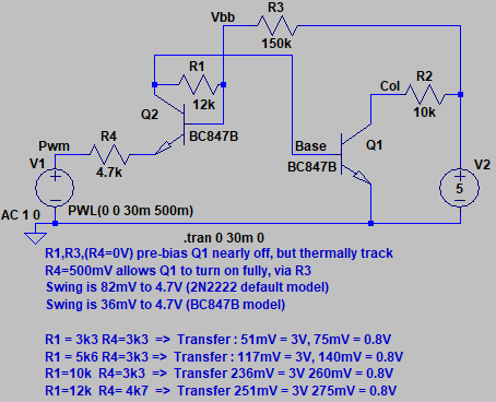
« Last Edit: April 03, 2023, 07:20:28 am by PCB.Wiz »
 

Offline JDWTopic starter

  • Frequent Contributor
  • **
  • Posts: 336
  • Country: jp
Re: Amplify 500mV 0-pk square wave to >2V for PIC MCU
« Reply #71 on: April 03, 2023, 08:21:58 am »
Does your function generator have a triangle wave ability ?

Yes.  To view all its selectable functions, view photo of function generator below.
Great, then use triangle setting and sweep the voltage from firstly a large range, like -5V to +5V, (10V p-p triangle) and confirm the output does change somewhere in that span
Then, you can 'zoom in' using offset and gain to check the actual switching point.


My attachments below show how your circuit simulates fine, but also show how it fails when breadboarded and tested on the bench — constant 60mV (basically GND) output instead of a waveform.  I am using a pair of 2SC1815 NPN transistors instead of the NPN part number you specified because I don't have your part in my inventory.
Good if you have simulate ok, you have a construction problem.

I see that has many HFE choices
hFE VCE=6.0V, IC=2.0mA (2SC1815) 70 700
hFE VCE=6.0V, IC=2.0mA (2SC1815-O) 70 140
hFE VCE=6.0V, IC=2.0mA (2SC1815-Y) 120 240
hFE VCE=6.0V, IC=2.0mA (2SC1815-GR) 200 400
hFE VCE=6.0V, IC=2.0mA (2SC1815-BL) 350 700

BC847B   hFE 200   450
So the 2SC1815-GR should be very close to BC847B, others less so.

If your symptom is 'stuck low' you may have miss matched transistors, here are some more resistor values I tabulated above, that shift the threshold.
When you have this HW working with the -5V-+5V triangle signal, you can fine tune the resistor values to get an appx 250mV threshold for your 500mV? actual signal.

[ Attachment Invalid Or Does Not Exist ]

If I completely kill the DC offset on my function generator and allow the generated waveform to swing above and below 0 V, which is not what I am seeing on the car side mind you, then I can just start to detect the inverted waveform at the output on my scope, be that a square wave or triangle wave, when the peak to peak amplitude of the function generator is 1.36V.  If I then increase the amplitude to 1.5 V, the output amplitude then becomes the same at 1.5 V. Even tiny increases to the function generator’s amplitude above 1.5 V will result in large amplitude increases on the output waveform. But as I start to increase the DC offset on the function generator, so as to match what I see on the car side (a 0v to peak square wave), the output waveform rapidly drops to zero.

In other words, the reasons I have not been able to get your circuit to work until now are twofold:

1) Until now, I’ve been using a DC offset to make sure the waveform appears with its low side at 0 V, but that results in no output waveform.

2) Until now, I’ve been using a 500 mV p-p waveform because that is what the amplitude is on the car side. But even if I kill the DC offset, a 500 mV p-p amplitude will not generate an output.

What are your thoughts in light of this?
« Last Edit: April 03, 2023, 08:26:34 am by JDW »
 

Offline peter-h

  • Super Contributor
  • ***
  • Posts: 3700
  • Country: gb
  • Doing electronics since the 1960s...
Z80 Z180 Z280 Z8 S8 8031 8051 H8/300 H8/500 80x86 90S1200 32F417
 

Offline JDWTopic starter

  • Frequent Contributor
  • **
  • Posts: 336
  • Country: jp
Re: Amplify 500mV 0-pk square wave to >2V for PIC MCU
« Reply #73 on: April 03, 2023, 11:02:48 am »
No, it is NPN. Maybe wrong post?

https://www.eevblog.com/forum/microcontrollers/amplify-500mv-0-pk-square-wave-to-gt2v-for-pic-mcu/msg4788365/#msg4788365

My earlier post is perhaps being called into question here.  Suffice it to say, what you see in my simulation attachments is what I built, and as you can see, I am using exclusively NPN transistors.  I wrote that earlier post because the hand-scratch looked like a PNP to me, but since no specific reply was given to me about that, I ignored that particular hand-scratched schematic and just built what you see in my simulation attachments.

I hope that is clear.
 

Online PCB.Wiz

  • Super Contributor
  • ***
  • Posts: 1548
  • Country: au
Re: Amplify 500mV 0-pk square wave to >2V for PIC MCU
« Reply #74 on: April 03, 2023, 09:15:48 pm »
If I then increase the amplitude to 1.5 V, the output amplitude then becomes the same at 1.5 V. Even tiny increases to the function generator’s amplitude above 1.5 V will result in large amplitude increases on the output waveform.

That's good, so you have gain and a threshold.
You can adjust the threshold by the resistor ratios. If you have a meter that can check hFE, try for some in the BC847B region.

See the table of resistors / thresholds, in the circuit of #70
« Last Edit: April 03, 2023, 09:17:59 pm by PCB.Wiz »


Share me

Digg  Facebook  SlashDot  Delicious  Technorati  Twitter  Google  Yahoo
Smf