Author Topic: Fan controller with PWM using STM32 chip  (Read 15963 times)

0 Members and 1 Guest are viewing this topic.

Offline DavidAlfa

  • Super Contributor
  • ***
  • Posts: 5912
  • Country: es
Re: Fan controller with PWM using STM32 chip
« Reply #50 on: May 30, 2021, 06:24:40 pm »
Yes. For single on/off applications you can put a 100K resistor to the gate and it will work.
But, as I said before, when it comes to fast switching, PWM, you need a strong drive for the mosfet to fully turn it on/off, to overcome the gate capacitance.
And to do that you need a low value resistor. But that gives another issue: if the mosfet blows, you'll have a low impedance path to the mcu pin and burn it and mayber more things connected to it.
You can't use a 10K resistor to drive a mosfet with PWM, the current is very limited and it will make the switching speeds very slow, to the point where you might set the mosfet half turned on.
A bipolar transistor doesn't have a gate to charge, negligible RC constant. Thus, as long as it has enough HFE(gain), you can drive it with high resistor values.

« Last Edit: May 30, 2021, 06:27:50 pm by DavidAlfa »
Hantek DSO2x1x            Drive        FAQ          DON'T BUY HANTEK! (Aka HALF-MADE)
Stm32 Soldering FW      Forum      Github      Donate
 
The following users thanked this post: agehall

Offline psysc0rpi0nTopic starter

  • Frequent Contributor
  • **
  • Posts: 326
  • Country: ar
Re: Fan controller with PWM using STM32 chip
« Reply #51 on: June 25, 2021, 09:50:26 pm »
Hello

How do you plan to program the MCU ?
I don't see any connector for either SWD or UART0

It's quite different now.


Well, I did my best. It might get better over time, I hope!


What a strange thing you made! Sorry I couldn't resist... :-DD.


Restore the transistor driver circuit as before. Just invert the PWM signal in the MCU registers!

With that circuit you're making a voltage divider. Not only that, a bipolar transistor needs current to turn on.
If you put a resistor in the emitter, the max voltage you can get there is Vbase-0.7.
So yes, luckly you will set the Mosfet gate to 2.4V. If it works at all.
Once the emitter voltage reaches that voltage, no more current can flow from base to emitter since the MCU sends 3.3V.

It seems you're using the one of these computer-like fans, they take little currents, maybe 300mA.... Consider replacing the whole thing with a Darlington transistor, it will be easier:


These have huge current gains, easily >1000. So with 5mA you can drive 5Amps.

I didn't come to this thread for a while. In the meantime I made some changes. Check above.
 

Offline DavidAlfa

  • Super Contributor
  • ***
  • Posts: 5912
  • Country: es
Re: Fan controller with PWM using STM32 chip
« Reply #52 on: June 26, 2021, 03:20:03 am »
Are you afraid of the thick traces? ;D

- Vdd comes out of the regulator, goes to C6, mcu, back to C8. Why? Put them in parallel in the same trace.
- Mcu Vdd pin goes to L1, L1 goes to C9 and C10 goes nowhere?
- VDDA goes to C11, but not connected to VDD through L1.

Ahh but you appplied via stitching to reinforce the ground, avoiding capacitance and current loops. Was you, or did the program make it automatically?  :-DD

I'm not a professional designer, but I like it... Check this one-boring-raining-day board design I did few months ago. I think it wasn't complete but I don't remember right know.
Perhabs you could get some tips by checking it (Or also might I, nobody knows everything!)
For the analog, since the current was only 2-3mA, I used a TL431 circuit designed for 7mA. For each analog device (op-amp, mcu vdda) I put a 10Ohm resistor and a 10uF cap after it.
10ohm, 2mA=20mV drop, so no problem... Use Proteus, the demo version will allow to see everything  :-+


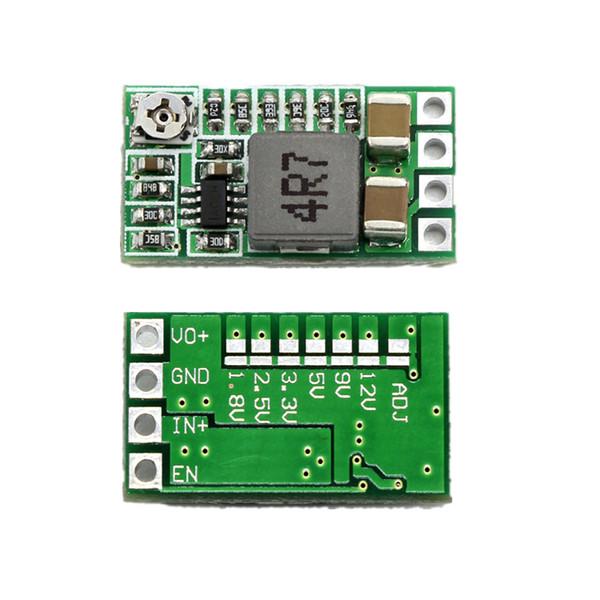
The red square in the bottom left is a MP2315 DC/DC regulator module:
« Last Edit: September 09, 2021, 09:45:31 am by DavidAlfa »
Hantek DSO2x1x            Drive        FAQ          DON'T BUY HANTEK! (Aka HALF-MADE)
Stm32 Soldering FW      Forum      Github      Donate
 

Offline psysc0rpi0nTopic starter

  • Frequent Contributor
  • **
  • Posts: 326
  • Country: ar
Re: Fan controller with PWM using STM32 chip
« Reply #53 on: June 26, 2021, 03:47:00 pm »
Are you afraid of the thick traces? ;D

- Vdd comes out of the regulator, goes to C6, mcu, back to C8. Why? Put them in parallel in the same trace. <-- Noob here. Inexperience, I guess
- Mcu Vdd pin goes to L1, L1 goes to C9 and C10 goes nowhere? <-- Check images below
- VDDA goes to C11, but not connected to VDD through L1. <-- Check images below

Ahh but you appplied via stitching to reinforce the ground, avoiding capacitance and current loops. Was you, or did the program make it automatically?  :-DD

I'm not a professional designer, but I like it... Check this one-boring-raining-day board design I did few months ago. I think it wasn't complete but I don't remember right know.
Perhabs you could get some tips by checking it (Or also might I, nobody knows everyt!)
For the analog, since the current was only 2-3mA, I used a TL431 circuit designed for 7mA. For each analog device (op-amp, mcu vdda) I put a 10Ohm resistor and a 10uF cap after it.
10ohm, 2mA=20mV drop, so no problem... Use Proteus, the demo version will allow to see everything  :-+


You gotta be kidding... You're not a pro? ahahah. ok
You're a pro to me.

Anyways, replying to your post:

About the C9, C10 an C11, it's strange because the connection is present on the schematics. C9, C10 and C11 should all be connected to each other and to VDDA. I have no idea why Kicad is not complaining about a missing connection.


About the Via stitching, it was me by hand, but there are plugins to do it I think. But someone told me to do it. I didn't know this improves ground and etc.
 

Offline DavidAlfa

  • Super Contributor
  • ***
  • Posts: 5912
  • Country: es
Re: Fan controller with PWM using STM32 chip
« Reply #54 on: June 26, 2021, 05:03:22 pm »
I don't know that software... is it kicad? I've wanting to learn it for a long time but I never started!
Can you send the file? Or is it a FBI top-secret fan controller? :-DD
« Last Edit: June 26, 2021, 05:07:39 pm by DavidAlfa »
Hantek DSO2x1x            Drive        FAQ          DON'T BUY HANTEK! (Aka HALF-MADE)
Stm32 Soldering FW      Forum      Github      Donate
 

Offline psysc0rpi0nTopic starter

  • Frequent Contributor
  • **
  • Posts: 326
  • Country: ar
Re: Fan controller with PWM using STM32 chip
« Reply #55 on: June 26, 2021, 05:15:31 pm »
I don't know that software... is it kicad? I've wanting to learn it for a long time but I never started!
Can you send the file? Or is it a FBI top-secret fan controller? :-DD

I say in my post it is Kicad.
What file you want? the schematic? You gotta keep it secret. It's not FBI but it's PSS. Keep it safe from the MOSSAD and the 8200 UNIT. xD
« Last Edit: June 26, 2021, 06:05:19 pm by psysc0rpi0n »
 

Offline DavidAlfa

  • Super Contributor
  • ***
  • Posts: 5912
  • Country: es
Re: Fan controller with PWM using STM32 chip
« Reply #56 on: June 26, 2021, 07:30:25 pm »
Haha I just want to see how it works and help showing the proper ways :-+ (And sell the design to China government)
Hantek DSO2x1x            Drive        FAQ          DON'T BUY HANTEK! (Aka HALF-MADE)
Stm32 Soldering FW      Forum      Github      Donate
 

Offline psysc0rpi0nTopic starter

  • Frequent Contributor
  • **
  • Posts: 326
  • Country: ar
Re: Fan controller with PWM using STM32 chip
« Reply #57 on: June 28, 2021, 08:27:02 pm »
Haha I just want to see how it works and help showing the proper ways :-+ (And sell the design to China government)

Well, as this was made as a project in Kicad, I think you need to have the same lybraries I have, the same folder structure, etc. But I can bzip (gzip, whatever) it to you and send it.

Will attach it in a few minutes if I can.
« Last Edit: June 28, 2021, 08:34:27 pm by psysc0rpi0n »
 

Offline psysc0rpi0nTopic starter

  • Frequent Contributor
  • **
  • Posts: 326
  • Country: ar
Re: Fan controller with PWM using STM32 chip
« Reply #58 on: June 30, 2021, 09:11:51 pm »
Haha I just want to see how it works and help showing the proper ways :-+ (And sell the design to China government)

Did you see that I have attached the super secret file you requested?
 

Offline DavidAlfa

  • Super Contributor
  • ***
  • Posts: 5912
  • Country: es
Re: Fan controller with PWM using STM32 chip
« Reply #59 on: July 01, 2021, 05:13:59 am »
Yes, but I didn't install kicad yet! :palm:
Hantek DSO2x1x            Drive        FAQ          DON'T BUY HANTEK! (Aka HALF-MADE)
Stm32 Soldering FW      Forum      Github      Donate
 

Offline psysc0rpi0nTopic starter

  • Frequent Contributor
  • **
  • Posts: 326
  • Country: ar
Re: Fan controller with PWM using STM32 chip
« Reply #60 on: July 02, 2021, 09:01:25 pm »
Well, I had to change the circuit a redo almost everything because I couldn't get the chip I was expecting to get. The one I was able to buy has more pins and is even more overkill for this, but the chip shortage is kinda global and the shop told me they could only send me the one I ordered in the first place in 2022. So I bought a different one which was the only one the shop had in stock.

But now I have a couple of questions about this new chip: STM32L412CB6T

The symbol I have for the chip is split into 2 units in Kicad. The power unit and the chip unit.
And the power unit is not exactly the same as it shows in the datasheet.

Datasheet shows Vref+ AND VDDA pins separated:


But the symbol in Kicad, shows them together at pins 9 and 24


So, my question is if the picture below is respecting the datasheet about the filtering/decoupling capacitors for VDDA and Vref+ pins (ignore L1, C8 and C9 as they are not in the datasheet).
In datasheet they say 10nF + 1uF between VDDA and VSSA and 100nF + 1uF for Vref+ and VSSA.
So, as there are 2 pairs of Vref+/VSSA, I have 2 pairs of 100nF + 1uF for them and one pair of 10nF + 1uF for VDDA/VSSA. Or should I add another pair for VDDA/VSSA once the symbol also has 2 pairs of this one too?
« Last Edit: July 02, 2021, 09:27:31 pm by psysc0rpi0n »
 

Offline psysc0rpi0nTopic starter

  • Frequent Contributor
  • **
  • Posts: 326
  • Country: ar
Re: Fan controller with PWM using STM32 chip
« Reply #61 on: July 05, 2021, 08:02:03 pm »
Ok, I ended up changing the symbol pin 24 name from VDDA/Vref+ to simply VDD because according to the datasheet, there is only one VDDA and 2 VDD.


So, I changed the original symbol pin 24 name from VDDA/Vref+ to VDD


So, for the filtering part, this is my circuit:


This is the PCB laayout


and the 3D view
« Last Edit: July 05, 2021, 08:04:41 pm by psysc0rpi0n »
 

Offline DavidAlfa

  • Super Contributor
  • ***
  • Posts: 5912
  • Country: es
Re: Fan controller with PWM using STM32 chip
« Reply #62 on: July 14, 2021, 11:17:12 am »
I finally installed Kicad and started fiddling around! Totally noob in this program but I had to start some day!

The stm32l412 lib is missing. I downloaded it from ultralibrarian, seems to be the same as yours. But after importing it, most connections were gone.
If you could reupload it with the libs....
Definitely the power connections in the pcb are wrong. For the power traces, use the thickest you can without exceding certain limits.Ex. do't use 10mm thickness for 10mA VDD!
But 2mm will certainly improve the impedances. For 12v and VDD/VDAA... then make it slimmer when reaching the stm32 or other small parts.
You don't need to use electrolytic caps, they're bulky and less reliable than ceramics, I'd put 10uF 0805 / 0603 ceramic caps.
Same for D1. Whenever you can go for smd instead through-hole, it make things easier. TH is only better to stand forces. Ex. a connector, or a heatsink.
Also such capacitor infantry is crazy! I'd put just 10uF+100nF packs. one at eachg side of the Vreg, and another two near the stm32 VDD and VDDA pins. That's a nice filter there!

« Last Edit: July 14, 2021, 11:46:03 am by DavidAlfa »
Hantek DSO2x1x            Drive        FAQ          DON'T BUY HANTEK! (Aka HALF-MADE)
Stm32 Soldering FW      Forum      Github      Donate
 

Offline psysc0rpi0nTopic starter

  • Frequent Contributor
  • **
  • Posts: 326
  • Country: ar
Re: Fan controller with PWM using STM32 chip
« Reply #63 on: July 15, 2021, 08:42:09 pm »
I finally installed Kicad and started fiddling around! Totally noob in this program but I had to start some day!

The stm32l412 lib is missing. I downloaded it from ultralibrarian, seems to be the same as yours. But after importing it, most connections were gone.
If you could reupload it with the libs....
Definitely the power connections in the pcb are wrong. For the power traces, use the thickest you can without exceding certain limits.Ex. do't use 10mm thickness for 10mA VDD!
But 2mm will certainly improve the impedances. For 12v and VDD/VDAA... then make it slimmer when reaching the stm32 or other small parts.
You don't need to use electrolytic caps, they're bulky and less reliable than ceramics, I'd put 10uF 0805 / 0603 ceramic caps.
Same for D1. Whenever you can go for smd instead through-hole, it make things easier. TH is only better to stand forces. Ex. a connector, or a heatsink.
Also such capacitor infantry is crazy! I'd put just 10uF+100nF packs. one at eachg side of the Vreg, and another two near the stm32 VDD and VDDA pins. That's a nice filter there!

Well, things are done. I'm not changing the whole thing again. If there is there nothing that will break the normal working of the circuit, then, I'll leave it as is.
Due to several factors, I'm already out of steam to keep doing this shitty project. I'm with this thing for weeks now and I'm already sick of it.

Yeah, one of my struggles is yet to judge when to use electrolytic, polarized, non-polarized, ceramic, film, etc. I've been told that from some value and up, they don't do them ceramic, they do it electrolytic, or something like that, but seems that this limit value is somewhat variable. It's not like that you can say that exactly from 1uF up, they are all electrolytic or polarized or so.

I have attached the files I have downloaded. I have changed the pin name of this chip because it didn't exactly match the datasheet. I have opened a ticket in STM32 site and they told me they would escalate the issue.

Hope this is enough to get you started.
 

Offline Bassman59

  • Super Contributor
  • ***
  • Posts: 2501
  • Country: us
  • Yes, I do this for a living
Re: Fan controller with PWM using STM32 chip
« Reply #64 on: July 16, 2021, 12:50:01 am »
Yeah, one of my struggles is yet to judge when to use electrolytic, polarized, non-polarized, ceramic, film, etc. I've been told that from some value and up, they don't do them ceramic, they do it electrolytic, or something like that, but seems that this limit value is somewhat variable. It's not like that you can say that exactly from 1uF up, they are all electrolytic or polarized or so.

The values shown in this thread -- 100 nF, 1 uF, 4.7 uF, -- are all available as ceramic caps in 0603, 0805, 1206, 1210, so pick a case size you like and the appropriate working voltages and get on with it.
 

Offline David Hess

  • Super Contributor
  • ***
  • Posts: 16620
  • Country: us
  • DavidH
Re: Fan controller with PWM using STM32 chip
« Reply #65 on: July 16, 2021, 04:13:03 pm »
you cannot pwm a 2 or 3-pin fan, that's not going to work as you might expect; you need a 4-pin pwm capable fan

Of course you can, that is being done all the time. Typical BLDC chassis fan is designed to be PWM'd on the low or high side.

Some brushless DC fans will work reasonably well and some will not; it depends on internal details like input capacitance.
 

Offline DavidAlfa

  • Super Contributor
  • ***
  • Posts: 5912
  • Country: es
Re: Fan controller with PWM using STM32 chip
« Reply #66 on: July 21, 2021, 03:26:38 am »
I'm unable to do anything. The whole schematic  layout is misaligned, cannot select a single pin! |O.

Edit: Ok you used 5mil grid for the schematic? That's crazy! :-DD
After aligning, everything was pretty smooth. Kicad seems good! :-+
Made few changes.. It seems the power_flag confused you! It's only used for power lines coming from elsewehere, ex. a connector.
So in theory only gnd and +12V would need them. I might be wrong, Kicad is completely new to me!


« Last Edit: July 21, 2021, 07:14:30 am by DavidAlfa »
Hantek DSO2x1x            Drive        FAQ          DON'T BUY HANTEK! (Aka HALF-MADE)
Stm32 Soldering FW      Forum      Github      Donate
 
The following users thanked this post: psysc0rpi0n


Share me

Digg  Facebook  SlashDot  Delicious  Technorati  Twitter  Google  Yahoo
Smf