Author Topic: STM 32F4 - output pin "speed" setting - what does it actually do?  (Read 873 times)

0 Members and 1 Guest are viewing this topic.

Online peter-hTopic starter

  • Super Contributor
  • ***
  • Posts: 3698
  • Country: gb
  • Doing electronics since the 1960s...
This has come up here before so I did some careful measurements.

Firstly, it does not appear to be done by paralleling different size MOSFETs, because the data sheet has just one current capability spec:
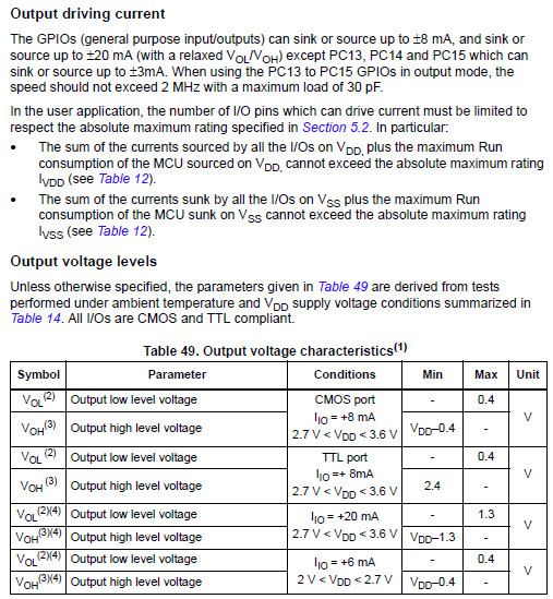


It looks like a slew rate limit - maybe done by switching in of different capacitors into the signal driving the output MOSFETs:


The last-1 option seems the one to go for because ir produces less ringing (not evident in the traces below) and the last two show the same risetime, so limited by the 350MHz Lecroy 3034 scope + 1GHz probe. Some devices ask for a fast risetime. One Adesto SPI FLASH wants 3ns and a Lyontech SPI RAM wants 1.5ns!
Z80 Z180 Z280 Z8 S8 8031 8051 H8/300 H8/500 80x86 90S1200 32F417
 

Offline redkitedesign

  • Regular Contributor
  • *
  • Posts: 111
  • Country: nl
    • Red Kite Design
Re: STM 32F4 - output pin "speed" setting - what does it actually do?
« Reply #1 on: October 05, 2022, 09:18:22 am »
Firstly, it does not appear to be done by paralleling different size MOSFETs, because the data sheet has just one current capability spec:

The datasheet is about the DC rating, not about the transition. Since the speed setting seems to affect the transistion (and is called speed setting, not strength setting!) the final output drive strength can very well be the same for all speed settings.

Note that IC manufacturers can make any shape and geometry of FET they like. A single channel FET with multiple (overlapping) gates is very well possible, and can thus be modulated in channel size and therefor resistance. Note that capacitors are expensive in IC design, they take too much space.
 

Online peter-hTopic starter

  • Super Contributor
  • ***
  • Posts: 3698
  • Country: gb
  • Doing electronics since the 1960s...
Re: STM 32F4 - output pin "speed" setting - what does it actually do?
« Reply #2 on: October 05, 2022, 09:58:01 am »
OK; they may have done that.

What surprises me is just how easy it is to get really clean waveforms with this CPU. Makes EMC compliance so much easier.
Z80 Z180 Z280 Z8 S8 8031 8051 H8/300 H8/500 80x86 90S1200 32F417
 

Offline thm_w

  • Super Contributor
  • ***
  • Posts: 6384
  • Country: ca
  • Non-expert
Re: STM 32F4 - output pin "speed" setting - what does it actually do?
« Reply #3 on: October 05, 2022, 09:00:54 pm »
Profile -> Modify profile -> Look and Layout ->  Don't show users' signatures
 
The following users thanked this post: pgo

Online T3sl4co1l

  • Super Contributor
  • ***
  • Posts: 21687
  • Country: us
  • Expert, Analog Electronics, PCB Layout, EMC
    • Seven Transistor Labs
Re: STM 32F4 - output pin "speed" setting - what does it actually do?
« Reply #4 on: October 05, 2022, 11:22:20 pm »
More likely implemented by varying the number of transistors driving the final inverter.  So Miller plus drive resistance controls slope, while current capacity is independent.

Nice on the AVRs that have it, too (XMEGA, Dx).

Tim
Seven Transistor Labs, LLC
Electronic design, from concept to prototype.
Bringing a project to life?  Send me a message!
 
The following users thanked this post: thm_w, peter-h, newbrain


Share me

Digg  Facebook  SlashDot  Delicious  Technorati  Twitter  Google  Yahoo
Smf